Archives
Chapter 1 Homework Determine the current flowing through an element
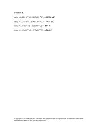
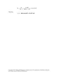
Solution 1.1 (a) q = 6.482×10¹⁷ x [-1.602×10⁻¹⁹ C] = –103.84 mC (b) q = 1. 24×1018 x [-1.602×10⁻¹⁹ C] = –198.65 mC (c) q = 2.46×10¹⁹ x [-1.602×10⁻¹⁹ C] = –3.941 C (d) q = 1.628×10²⁰ x [-1.602×10⁻¹⁹ C] […]
Chapter 1 Homework toaster takes roughly 4 minutes to heat four slices of bread
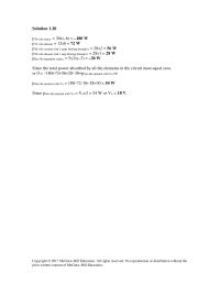
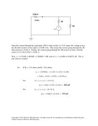
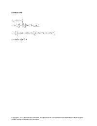
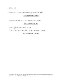
Solution 1.20 p30 volt source = 30x(–6) = –180 W p12 volt element = 12×6 = 72 W p28 volt e.ement with 2 amps flowing through it = 28×2 = 56 W p28 volt element with 1 amp flowing through […]
Chapter 10 Homework After simulation, we print out the output file which includes
°∠= °∠ °∠ = − =43.911.0 43.1–01.40 904 j40 4j o V Therefore, =)t(v o 100 cos(4×10⁴ t + 91.43°) mV Copyright © 2017 McGraw–Hill Education. All rights reserved. No reproduction or distribution without the prior written consent of McGraw–Hill […]
Chapter 10 Homework Although there are many ways to work this problem
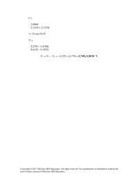
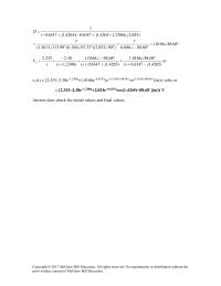
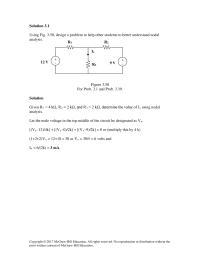
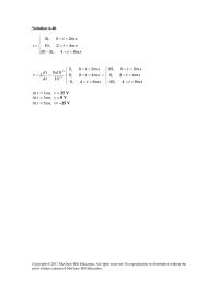
I = 2.0000 2.1210 + 2.1210i >> V=inv(Y)*I V = 5.2793 – 5.4190i 9.6145 – 9.1955i Vs = V1 – V2 = –4.335 + j3.776 = 5.749∠138.94˚ V. Copyright © 2017 McGraw–Hill Education. All rights reserved. No reproduction or distribution […]
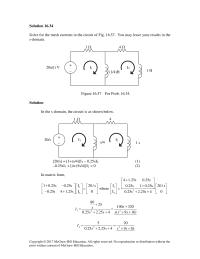
Chapter 10 Homework Find the Thevenin and Norton equivalent circuits at terminals a-b of
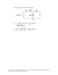
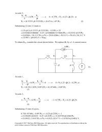
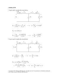
To find th V , consider the circuit in Fig. (b). )12060( 2j1 4j )12060( 20j10j5 20j th °∠ + =°∠ +− =V = 107.3∠146.56° V = °∠ °∠ == 7.33–633.21 56.1463.107 th th N Z V I 4.961∠-179.7° A […]
Chapter 10 Homework If we transform the voltage source, we have the circuit in Fig
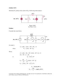
Solution 10.32 Determine Vo and Io in the circuit of Fig. 10.80 using mesh analysis. Figure 10.80 For Prob. 10.32. Solution Consider the circuit below. For mesh 1, 03)30–10(2)42( 1 =+°∠−+ o jVI where )30–10(2 1 IV −°∠= o 3 […]
Chapter 10 Homework Let Vo be the voltage across the dependent current source
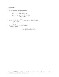
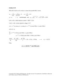
Solution 10.1 We first determine the input impedance. 1 1 10 10H j L jx j ω → = = 1 1 1 0.1 10 1 Fj jC jx ω → = = − 1 1 11 1 […]
Chapter 10 Homework This must be compensated for by 3v=A
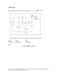
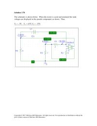
Solution 10.83 The schematic is shown below. The frequency is 15.159 2 1000 2/f = π =πω= When the circuit is saved and simulated, we obtain from the output file FREQ VM(1) VP(1) 1.592E+02 6.611E+00 -1.592E+02 Thus, vo = 6.611cos(1000t […]
Chapter 10 Homework With these, we transform the voltage source in Fig
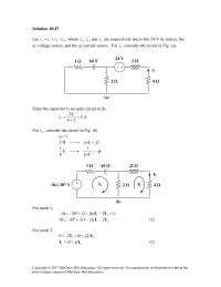
Solution 10.47 Let 321o iiii ++= , where 1 i , 2 i , and 3 i are respectively due to the 24-V dc source, the ac voltage source, and the ac current source. For 1 i , consider the […]
Chapter 11 Homework Calculate the maximum power absorbed by the load
Solution 11.1 )t50cos(160)t(v = i(t) = –33sin(50t–30˚) = 33cos(50t–30˚+180˚–90˚) = 33cos(50t+60˚) p(t) = v(t)i(t) = 160x33cos(50t)cos(50t+60˚) = 5280(1/2)[cos(100t+60˚)+cos(60˚)] = [1.320+2.640cos(100t+60˚)] kW. P = [VmIm/2]cos(0–60˚) = 0.5x160x33×0.5 = 1.320 kW. Copyright © 2017 McGraw–Hill Education. All rights reserved. No reproduction or […]
Chapter 11 Homework A power transmission system is modeled as shown in
Solution 11.83 (a) 2 2 W1.68835cos840cos === o SP θ (b) S = 840 VA (c) VAR 8.48135sin840sin === o SQ θ (d) (lagging) 8191.035cos/=== o SPpf ooo VIS35840)258)(60210( 1 1∠=−∠∠== ∗ Copyright © 2017 McGraw–Hill Education. All rights reserved. […]
Chapter 11 Homework First we identify a reference node and then label the unknown nodes
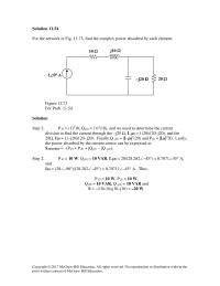
Solution 11.54 For the network in Fig. 11.73, find the complex power absorbed by each element. Figure 11.73 For Prob. 11.54. 20 Ω –j20 Ω 1∠0° A Solution Step 1. P10 = (1)210, Qj10 = (1)2(10), and we need to […]
Chapter 11 Homework I would add a capacitor in parallel with the hair dryer
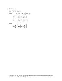
Solution 11.68 Let cLR SSSS ++= where 0jRI 2 1 jQP2 oRRR +=+=S LI 2 1 j0jQP 2 oLLL ω+=+=S C 1 I 2 1 j0jQP2 occc ω ⋅−=+=S Hence, =S […]
Chapter 11 Homework Problem The voltage applied to a 10-ohm resistor is
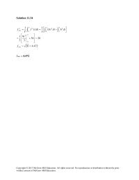
Solution 11.34 472.420 2036 3 9 3 1 2 0 3 == = += rms f t frms = 4.472 6)3( 3 1 )( 1 3 2 2 2 0 2 0 22 […]
Chapter 11 Homework We now find The by writing and solving a nodal
At node 2, )25.025.0(75.00 4 5.0 4 21 2 1 21 jVV j V V VV +−+=→=+ − or V1 = (0.33333–j0.33333)V2 = (0.4714∠–45°)V2 (2) Substituting (2) into (1) leads to (1.25+j0.2)( 0.33333–j0.33333)V2 – 0.25V2 = 25 = [0.41666+0.066666 – […]
Chapter 12 Homework In a balanced three-phase wye-wye system
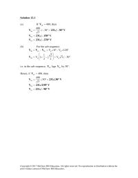
Solution 12.1 (a) If 400 ab =V , then =°∠= 30– 3 400 an V V30–231 °∠ = bn V V150–231 °∠ = cn V V270–231 °∠ (b) For the acb sequence, °∠−°∠=−= 120V0V ppbnanab VVV °∠= […]
Chapter 12 Homework A balanced three-phase generator has an abc phase sequence with
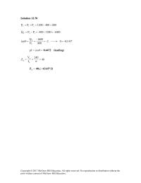
Solution 12.70 8004001200PPP 21T =−=+= 1600–1200400–PPQ 12T =−=−= °=θ→===θ -63.43-2 800 1600– P Q tan T T =θ= cospf (leading)4472.0 40 6 240 I V Z L L p= == = p Z Ω°∠ 63.43–40 Copyright © 2017 McGraw–Hill Education. […]
Chapter 12 Homework Consider the circuit below
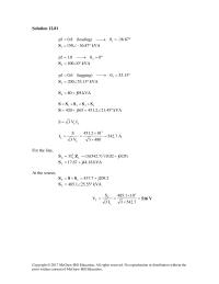
Solution 12.81 °=θ→= 87.36–(leading)8.0pf 1 kVA36.87–150 1°∠=S °=θ→= 00.1pf 2 kVA0100 2°∠=S °=θ→= 13.53(lagging)6.0pf 3 kVA53.13200 3°∠=S kVA95j80 4 +=S 4321 SSSSS +++= kVA21.452.451165j420 °∠=+=S LL IV3S = A7.542 4803 102.451 V3 S I 3 L L= × × == […]
Chapter 12 Homework Design a problem to help other students to better understand power
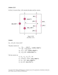
Solution 12.19 For the ∆–∆ circuit of Fig. 12.50, calculate the phase and line currents. Figure 12.50 For Prob. 12.19. Solution °∠=+= ∆18.4362.3110j30Z The phase currents are = °∠ °∠ == ∆ 18.4362.31 0440 Z V I ab AB 13.915∠–18.43° […]
Chapter 12 Homework Once the circuit is simulated, we get an output
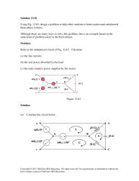
Solution 12.56 Using Fig. 12.63, design a problem to help other students to better understand unbalanced three–phase systems. Although there are many ways to solve this problem, this is an example based on the same kind of problem asked in […]
Chapter 12 Homework Then we can calculate phase currents
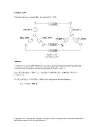
Solution 12.39 Find the real power absorbed by the load in Fig. 12.58. c b B C (36+j28) Ω (36+j28) Ω − + 100∠–30° V 100∠–150° + − (4+j2) Ω (4+j2) Ω Figure 12.58 For Prob. 12.39. Solution To find […]
Chapter 13 Homework Obtain V1 and V2 in the ideal transformer circuit of
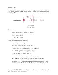
Solution 13.29 In the circuit of Fig. 13.97, find the value of the coupling coefficient k that will make the 10-Ω resistor dissipate 1.28 kW. For this value of k, find the energy stored in the coupled coils at t […]
Chapter 13 Homework The coils must be series opposing to give 14 V
Solution 13.87 ZTh = ZL/n2 or n = 300/75Z/Z ThL= = 0.5 Copyright © 2017 McGraw–Hill Education. All rights reserved. No reproduction or distribution without the prior written consent of McGraw–Hill Education. Solution 13.88 n = V2/V1 = I1/I2 or […]
Chapter 13 Homework After simulation, the output file includes
Solution 13.77 (a) This is a single phase transformer. V1 = 13.2 kV, V2 = 120 V n = V2/V1 = 120/13,200 = 1/110, therefore n = 1/110 or 110 turns on the primary to every turn on the secondary. […]
Chapter 13 Homework Then we can do source transformation to convert
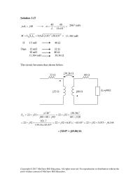
Solution 3.17 3 40 40 40 2666.67 15 10 jL j Lx ωω − = → = = = 33 12 0.6 12 10 30 10 62.35 mHM k LL x x x −− = = = If 15 […]
Chapter 13 Homework We can also use the equivalent T-section for the
Solution 13.1 For coil 1, L1 – M12 + M13 = 12 – 8 + 4 = 8 For coil 2, L2 – M21 – M23 = 16 – 8 – 10 = – 2 For coil 3, L3 + […]
Chapter 13 Homework When individuals travel, their electrical appliances need to
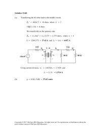
Solution 13.60 (a) Transferring the 40-ohm load to the middle circuit, ZL’ = 40/(n’)2 = 10 ohms where n’ = 2 10||(5 + 10) = 6 ohms We transfer this to the primary side. Zin = 4 + 6/n2 = […]
Chapter 13 Homework where Z3 is reflected to the middle circuit
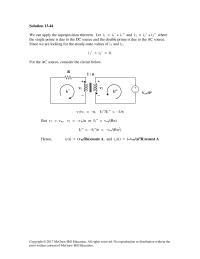
Solution 13.44 We can apply the superposition theorem. Let i1 = i1’ + i1” and i2 = i2’ + i2” where the single prime is due to the DC source and the double prime is due to the AC source. […]
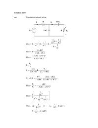
Chapter 14 Homework Solution 1457 A Consider The Circuit Below
Solution 14.57 (a) Consider the circuit below. Z V I s = )sRC2(RsC2 sC1 s 1 + = + =Z V II 222 s 1o CRssRC31 )sRC2(sC sRC2 R R++ + ⋅ + == V IV 222 s o CRssRC31 […]
Chapter 14 Homework The response shows that the circuit is a high-pass filter.
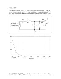
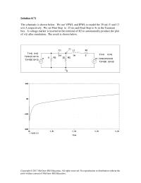
Solution 14.88 The schematic is shown below. We insert a voltage marker to measure Vo. In the AC Sweep box, we set Total Points = 101, Start Frequency = 1, and End Frequency = 100. After simulation, we obtain the […]
Chapter 14 Homework This Parallel Resonant Circuit O 44721 Rads
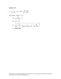
Solution 4.39 222 LR LjR CjCj LjR 1 Yω+ ω− +ω=ω+ ω+ = At resonance, 0)Im( =Y , i.e. 0 LR L C22 0 2 0 0= ω+ ω −ω C L LR 22 0 2 =ω+ 2 -36–-32 2 […]
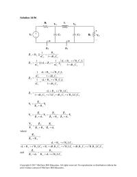
Chapter 14 Homework We obtain R Th across the capacitor
Solution 14.96 22 2 L1 CsR1 sC ||R + ==Z + ++ =+= 2L 2L 2 L 1 1 1 2CsR1 LCRsRsL || sC 1 )sL(|| sC 1ZZ L R 1 2L 2L 2 […]
Chapter 14 Homework It is evident from the response that the circuit represents a
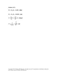
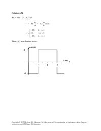
Solution 14.74 Ω=== 300100x3RK‘R 1m1 Ω=== k 1100x10RK‘R 2m2 H 200)2( 10 10 L K K ‘L 6 2 f m µ=== nF 1 10 10 1 KK C ‘C 8 fm === Copyright © 2017 McGraw–Hill Education. All rights […]
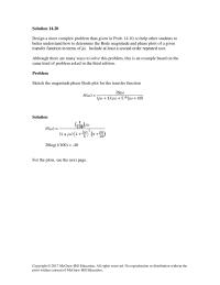
Chapter 14 Homework Sketch the magnitude phase Bode plot for the transfer function
Solution 14.20 Design a more complex problem than given in Prob. 14.10, to help other students to better understand how to determine the Bode magnitude and phase plots of a given transfer function in terms of jω. Include at least […]
Chapter 14 Homework The magnitude and phase plots are shown below
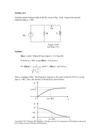
Solution 14.1 Find the transfer function Io/Ii of the RL circuit in Fig. 14.68. Express the transfer function using ωo = R/L. Figure 14.68 For Prob. 14.1. Solution H(ω) = Io/Ii = [RjωL/(R+jωL)]/(jωL) = 1/(1+jωL/R) If we let ωo = […]
Chapter 15 Homework Although There Are Many Ways Solve This
Solution 15.19 Since [ ] 1)t( =δL and 2T = , =)s(F s2– e1 1 − Copyright © 2017 McGraw–Hill Education. All rights reserved. No reproduction or distribution without the prior written consent of McGraw–Hill Education. Solution 15.20 Using Fig. […]
Chapter 15 Homework Take the Laplace transform of each term
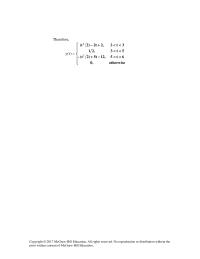
Therefore, =)t(y <<−+ << otherwise,0 6t5,12t5)2t(– 5t3,21 2 <<+− 3t2,2t2)2t( 2 Copyright © 2017 McGraw–Hill Education. All rights reserved. No reproduction or distribution without the prior written consent of McGraw–Hill Education. Solution 15.45 […]
Chapter 15 Homework this is an example based on the same kind of problem
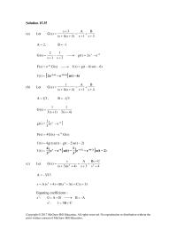
Solution 15.35 (a) Let 2s B 1s A )2s)(1s( 3s )s(G + + + = ++ + = 2A = , -1B = 2t–t– ee2)t(g 2s 1 1s 2 )s(G −=→ + − + = )6t(u)6t(g)t(f)s(Ge)s(F -6s −−=→= =)t(f [ […]
Chapter 15 Homework going back to the original and eliminating the denominators we get
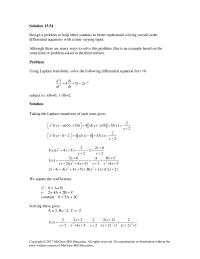
Solution 15.54 Design a problem to help other students to better understand solving second order differential equations with a time varying input. Although there are many ways to solve this problem, this is an example based on the same kind […]
Chapter 15 Homework Taking the Laplace transform of each term
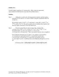
Solution 15.1 Find the Laplace transform of 5 sin(at)cos(bt). [Hint: using the exponential representation for both functions may make this problem easier.] Solution. Step 1. Although we could work with trigonometric identities and the Laplace transforms for sin and cos, […]
Chapter 16 Homework Design Problem Help Other Students
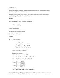
Solution 16.74 Design a problem to help other students to better understand how to find outputs when given a transfer function and an input. Although there are many ways to solve this problem, this is an example based on the […]
Chapter 16 Homework First select the inductor current iL
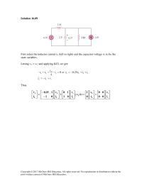
Solution 16.89 First select the inductor current iL (left to right) and the capacitor voltage vC to be the state variables. Letting vo = vC and applying KCL we get: sCL sLCCs C CL vvi iivvori v vi +−= ++−==−++− […]
Chapter 16 Homework Then solve for I, perform a partial fraction expansion
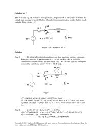
Solution 16.19 The switch in Fig. 16.42 moves from position A to position B at t=0 (please note that the switch must connect to point B before it breaks the connection at A, a make before break switch). Find v(t) […]
Chapter 16 Homework Transform the equation into the s-domain and solve for
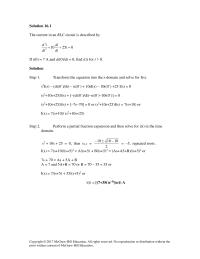
Solution 16.1 The current in an RLC circuit is described by 2 2 10 25 0 d i di i dt dt + += If i(0) = 7 A and di(0)/dt = 0, find i(t) for t > 0. Solution […]
Chapter 16 Homework First we need to determine the initial conditions which in this
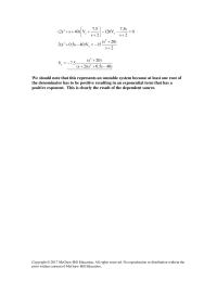
)40s5.0s)(2s( )20s( 5.7V 2s )20s( 15V)40s5.0s(2 2 2 x 2 x 2 −++ + −= + + −=−+ We should note that this represents an unstable system because at least one root of the denominator has to be positive resulting […]
Chapter 16 Homework Now we can calculate B by multiplying both sides by
Solution 16.34 Solve for the mesh currents in the circuit of Fig. 16.57. You may leave your results in the s-domain. Figure 16.57 For Prob. 16.34. Solution In the s-domain, the circuit is as shown below. [20/s] = [1+(s/4)]I1 – […]
Chapter 16 Homework When the input to a system is a unit step function
°∠= °−∠ = °∠°∠°∠ = 68.880166.1 68.88886.6 7 )90853.2)(33.67546.1)(99.1135613.1( 7 )4265.16347.0( 68.880166.1 )4265.16347.0( 68.880166.1 )2306.1( 38.2333.2 jsjsss V o −+ °∠ + ++ °−∠ + + − += or vo(t) = [2.333–2.38e–1.2306t+1.0166e–0.6347t(e–(1.4265t+88.68˚)+e(1.4265t+88.68˚))]u(t) volts or = [2.333–2.38e–1.2306t+2.033e–0.6347tcos(1.4265t+88.68˚)]u(t) V. Answer does check […]
Chapter 17 Homework A This Periodic With Which
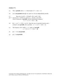
Solution 17.1 (a) This is periodic with ω = π which leads to T = 2π/ω = 2. (b) y(t) is not periodic although sin t and 4 cos 2πt are independently periodic. (c) Since sin A cos B = […]
Chapter 17 Homework If v 2 (t) is shifted by 4 along the vertical axis,
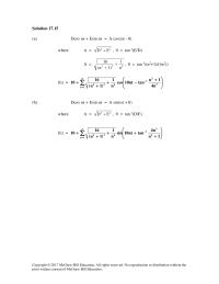
Solution 17.15 (a) Dcos ωt + Esin ωt = A cos(ωt – θ) where A = 22 ED + , θ = tan-1(E/D) A = 622 n 1 )1n( 16 + + , θ = tan-1((n2+1)/(4n3)) f(t) = ∑ ∞ […]
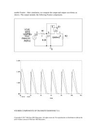
Chapter 17 Homework Due to the complexity of the terms, we consider only the DC
enable Fourier. After simulation, we compare the output and output waveforms as shown. The output includes the following Fourier components. FOURIER COMPONENTS OF TRANSIENT RESPONSE V(1) Copyright © 2017 McGraw–Hill Education. All rights reserved. No reproduction or distribution without the […]
Chapter 17 Homework In the Transient dialog box, we enter Print Step
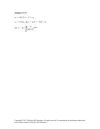
Solution 17.57 ao = (6/–2) = –3 = co cn = 0.5(an –jbn) = an/2 = 3/(n3 – 2) f(t) = ∑ ∞ ≠−∞=− +− 0n n nt50j 3e 2n 3 3 Copyright © 2017 McGraw–Hill Education. All rights reserved. […]
Chapter 17 Homework The average power dissipation caused by the dc component
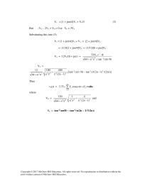
Vs = [1 + jnπ/4]Vx + Vo/3 (3) But –Vx – 2Vx + Vo = 0 or Vo = 3Vx Substituting this into (3), Vs = [1 + jnπ/4]Vx + Vx = [2 + jnπ/4]Vx = (1/3)[2 + jnπ/4]Vo = […]
Chapter 17 Homework We can now solve for vo
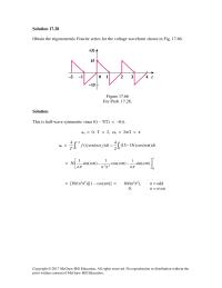
Solution 17.28 Obtain the trigonometric Fourier series for the voltage waveform shown in Fig. 17.66. Figure 17.66 For Prob. 17.28. Solution This is half–wave symmetric since f(t − T/2) = −f(t). ao = 0, T = 2, ωo = 2π/2 […]
Chapter 18 Homework Figure 1846 For Prob 1844 Solution J
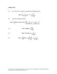
Solution 18.35 (a) x(t) = f[3(t-1/3)]. Using the scaling and time shifting properties, )j6( e e 3/j2 1 3 1 )(X 3/j 3/j ω+ = ω+ =ω ω− ω− (b) Using the modulation property, […]
Chapter 18 Homework Fourier Transform Given Wave Shape Although There
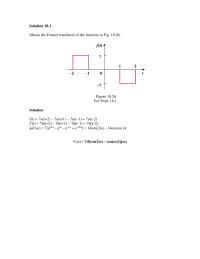
Solution 18.1 Obtain the Fourier transform of the function in Fig. 18.26. Figure 18.26 For Prob. 18.1. Solution f(t) = 7u(t+2) – 7u(t+1) – 7u(t–1) + 7u(t–2) f’(t) = 7δ(t+2) – 7δ(t+1) – 7δ(t–1) + 7δ(t–2) jωF(ω) = 7(ej2ω – […]
Chapter 18 Homework The Fourier transform of each term gives
Solution 18.15 (a) =−=ω ω−ω 3j3j ee)(F ω3sinj2 (b) Let ω− =ω−δ= j e2)(G),1t(2)t(g =ω)(F F ∫∞− tdt)t(g )()0(F j )(G ωδπ+ ω ω = )()1(2 j e2 j ωδ−πδ+ ω = ω− = ω […]
Chapter 18 Homework what is the total energy in f(t)?
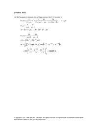
Solution 18.51 In the frequency domain, the voltage across the 2-Ω resistor is 2 2 10 20 () , 2 2 1 ( 1)( 2) s V V sj j j j ss ωω ω ωω = = = = […]
Chapter 19 Homework Alternatively From The Given Circuit 01
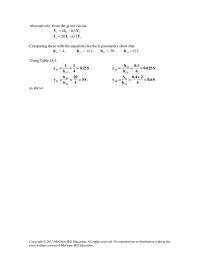
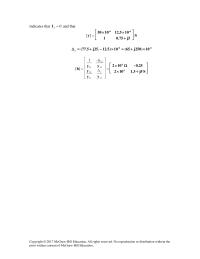
Alternatively, from the given circuit, 211 1.04 VIV −= 212 1.020 VII += Comparing these with the equations for the h parameters show that 4 11 =h , -0.1 12 =h , 20 21 =h , 1.0 22 =h Using […]
Chapter 19 Homework Consequently, the y parameter equivalent circuit is shown
Substituting these into (1) and (2), s11 s 1111s1s Zz V IIzZIV + =→=− s11 s21 1212 Zz Vz IzV + == == 2Th VV s11 s21 Zz Vz + Copyright © 2017 McGraw–Hill Education. All rights reserved. No reproduction […]
Chapter 19 Homework To get B and D, consider the circuit in Fig
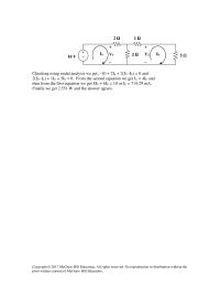
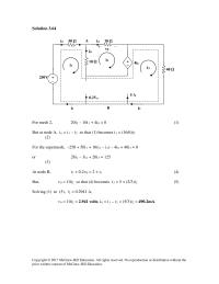
Checking using nodal analysis we get, –10 + 2Ia + 2(Ia–Ib) = 0 and 2(Ib–Ia) + 1Ib + 5Ib = 0. From the second equation we get Ia = 4Ib and then from the first equation we get 8Ib + […]
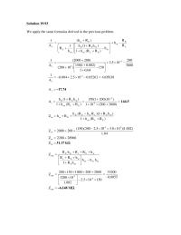
Chapter 19 Homework We apply the same formulas derived in the previous problem.
Solution 19.93 We apply the same formulas derived in the previous problem. E Eie R h )Rh( 1−+ + = = +×+ = ++ = )3800200(101 )RR(h1 A5– ELoe i 5.144 )RR(h1 )hR1)(RhR(h RhZ ELoe oeELreEfe Eiein ++ +− ++= […]
Chapter 19 Homework If we calculate the gain for the circuit we get At = Vo
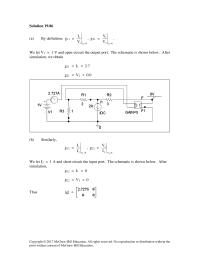
Solution 19.86 (a) By definition, g11 = 0I 1 1 2 V I = , g21 = 0I 2 1 2 V V = . We let V1 = 1 V and open-circuit the output port. The schematic is shown […]
Chapter 19 Homework If we convert the current source to a voltage source
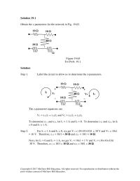
Solution 19.1 Obtain the z parameters for the network in Fig. 19.65. 10 Ω 10 Ω 10 Ω Figure 19.65 For Prob. 19.1. Solution Step 1. Label the circuit to allow us to determine the z–parameters. The z–parameter equations are, […]
Chapter 19 Homework In the AC Sweep box, we type Total Pts
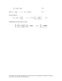
222121o IzIzV += (2) But Lo2L2o Z/VIZIV −=→−= (3) From (2) and (3) , +=→−= 21L 22 21 o1 L o 22121o zZ z z 1 VI Z V zIzV (4) Substituting (3) […]
Chapter 19 Homework It is better to work with z parameters and then convert to y parameters
indicates that 0 2=I and that =][y S 5j75.01 105.121050 -6-6 + ×× -6-6 y10)250j65(10)5.12.25j5.77( ×+=×−+=∆ = ∆ = 11 y 11 […]
Chapter 19 Homework It is easy to find the z parameters and then transform
Solution 19.50 To get a and c, consider the circuit below. I1=0 2 s I2 + + V1 4/s V2 – – 2 1 2 2 2 21 s25.01 V V aV 4s 4 V s/4s s/4 V+==→ + = […]
Chapter 2 Homework Checking with PSpice we get
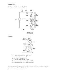
Solution 2.57 Find Req and I in the circuit of Fig. 2.121. Figure 2.121 For Prob. 2.57. Solution Rab = Ω== ++ 30 10 300 10 101010101010 xxx Rac = 216/(8) = 27Ω, Rbc = 36 Ω Rde = Ω== […]
Chapter 2 Homework Converting the delta subnetwork into wye gives the circuit below.
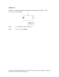
Solution 2.71 Figure 2.131 represents a model of a solar photovoltaic panel. Given that Vs = 95 V, R1 = 25 Ω, iL = 2 A, find RL. Figure 2.131 For Prob. 2.71. Step 1. Vs = iL(R1+RL) or RL […]
Chapter 2 Homework Problem What Value The Circuit Fig 2114
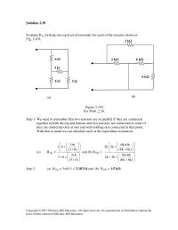
Solution 2.39 Evaluate Req looking into each set of terminals for each of the circuits shown in Fig. 2.103. 3 Ω 6 Ω 6 Ω 3 Ω 6 kΩ 6 kΩ 2 kΩ (a) (b) Figure 2.103 For Prob. 2.39. […]
Chapter 2 Homework Solution Step All Need Combine All The
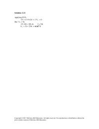
Solution 2.21 Applying KVL, -15 + (1+5+2)I + 2 Vx = 0 But Vx = 5I, -15 +8I + 10I =0, I = 5/6 Vx = 5I = 25/6 = 4.167 V Copyright © 2017 McGraw–Hill Education. All rights reserved. […]
Chapter 2 Homework Use at least two resistors and one voltage source
Solution 2.1 Design a problem, complete with a solution, to help students to better understand Ohm’s Law. Use at least two resistors and one voltage source. Hint, you could use both resistors at once or one at a time, it […]
Chapter 3 Homework Establish two unknown loop currents and write the mesh equations
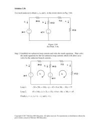
Solution 3.36 Use mesh analysis to obtain ia, ib, and ic in the circuit shown in Fig. 3.84. 30 V − + 5 Ω 10 Ω 15 Ω 20 Ω 45 V – + ia ib ic Figure 3.84 For […]
Chapter 3 Homework Resistor Series With The Source 12
Solution 3.1 Using Fig. 3.50, design a problem to help other students to better understand nodal analysis. Figure 3.50 12 V + − Ix R3 9 V + − For Prob. 3.1 and Prob. 3.39. Solution Given R1 = 4 […]
Chapter 3 Homework The mesh equations are obtained as follows.
Solution 3.64 40 Ω i1 i2 i3 – + 250V + – 4i 0 10 Ω 5 A i 0 v0 For mesh 2, 20i2 – 10i1 + 4i0 = 0 (1) But at node A, io = i1 – […]
Chapter 3 Homework Using Matlab Leads 719
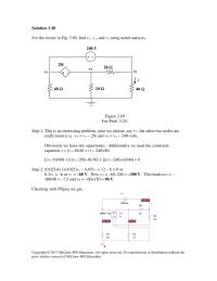
Solution 3.20 For the circuit in Fig. 3.69, find v1, v2, and v3 using nodal analysis. 20 Ω 20i + − 40 Ω 10 Ω 40 Ω v2 v3 v1 i Figure 3.69 For Prob. 3.20. Step 1. This is […]
Chapter 3 Homework We note that we have three unknown loop currents
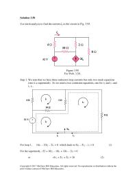
Solution 3.50 Use mesh analysis to find the current io in the circuit in Fig. 3.95. 52 V Figure 3.95 For Prob. 3.50. Step 1. We note that we have three unknown loop currents but only two mesh equations (one […]
Chapter 3 Homework When the circuit is saved and simulated, we obtain the
Solution 3.78 The schematic is shown below. When the circuit is saved and simulated the node voltages are displayed on the pseudo components as shown. Thus, ,V15 V,5.4 V,3 321 −==−= VVV . Copyright © 2017 McGraw–Hill Education. All rights […]
Chapter 4 Homework By interchanging the ammeter and the 12-V voltage source
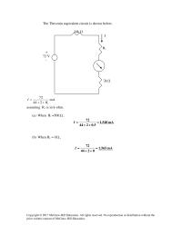
The Thevenin equivalent circuit is shown below. 44k Ω I Ri + 72 V – 2k Ω mA 244 72 R I ++ = i assuming Ri is in k-ohm. (a) When Ri =500 Ω , mA 1.548 5.0244 72 […]
Chapter 4 Homework Find the Thevenin equivalent at terminals a-b of
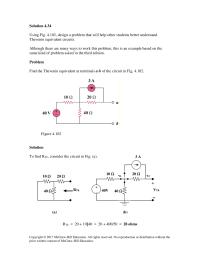
Solution 4.34 Using Fig. 4.102, design a problem that will help other students better understand Thevenin equivalent circuits. Although there are many ways to work this problem, this is an example based on the same kind of problem asked in […]
Chapter 4 Homework Since the resistance remains the same we get can use
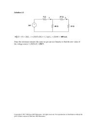
Solution 4.1 Ω=+ 20)1525(40 , i = [30/(5+20)] = 1.2 and io = i20/40 = 600 mA. Since the resistance remains the same we get can use linearity to find the new value of the voltage source = (30/0.6)5 = […]
Chapter 4 Homework Since we only have two independent sources
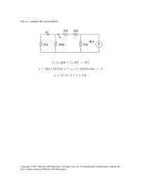
For io3, consider the circuit below. 3 + 2 + 4||10 = 5 + 20/7 = 55/7 i2 = [5/(5 + 55/7)]18 = 7, io3 = [–10/(10 + 4)]i2 = –5 io = 12 – 6 – 5 = 1 […]
Chapter 4 Homework Thevenin Equivalent Circuit Looking Into The Terminals
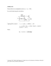
Solution 4.63 Because there are no independent sources, IN = Isc = 0 A RN can be found using the circuit below. Applying KCL at node 1, v1 = 1, and vo = (20/30)v1 = 2/3 io = (v1/30) – […]
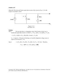
Chapter 4 Homework We note that there is a dependent source which
Solution 4.47 Obtain the Thevenin and Norton equivalent circuits of the circuit in Fig. 4.114 with respect to terminals a and b. 20 Ω 20Ix + − 1 amp 20 Ω Ix Figure 4.114 For Prob. 4.47. Solution Step 1. […]
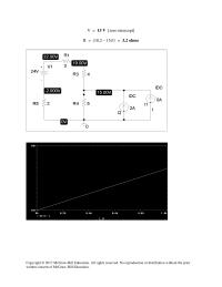
Chapter 4 Homework We perform a dc sweep on the current source
V = 15 V [zero intercept] R = (18.2 – 15)/1 = 3.2 ohms Copyright © 2017 McGraw–Hill Education. All rights reserved. No reproduction or distribution without the prior written consent of McGraw–Hill Education. Solution 4.78 The schematic is shown […]
Chapter 5 Homework Determine the voltage input to the inverting terminal of
Solution 5.1 (a) Rin = 1.5 MΩ (b) Rout = 60 Ω (c) A = 8×10⁴ Therefore AdB = 20 log 8×104 = 98.06 dB Copyright © 2017 McGraw–Hill Education. All rights reserved. No reproduction or distribution without the prior […]
Chapter 5 Homework Label the reference and node voltages in the circuit
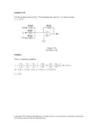
Solution 5.39 For the op amp circuit in Fig. 5.76, determine the value of v2 in order to make vo = –7.5 V. 10 kΩ − + 50 kΩ v2 vo 50 kΩ 20 kΩ –3 V 5 V Figure […]
Chapter 5 Homework Let v 1 be the output of the first op amp and
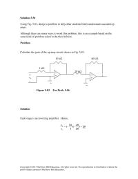
Solution 5.56 Using Fig. 5.83, design a problem to help other students better understand cascaded op amps. Although there are many ways to work this problem, this is an example based on the same kind of problem asked in the […]
Chapter 5 Homework Returning to our first equation we get
v4 + − 2R 2R 11/4A Since the current through the equivalent 21R/11-ohm resistor is (11/4) amps, the voltage across the 2R-ohm resistor on the right is (21/4)R volts. This means the current going through the 2R- ohm resistor is […]
Chapter 5 Homework Solution 576 The Schematic Shown Below
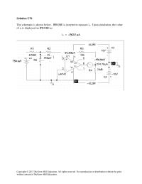
Solution 5.76 The schematic is shown below. IPROBE is inserted to measure io. Upon simulation, the value of io is displayed on IPROBE as io = –562.5 µA 750 mV 0.750V 375mV –19.358uV –11.25V –936.8mV 2 kΩ 11.25V Copyright © […]
Chapter 5 Homework The Current Through The K Resistor Equal
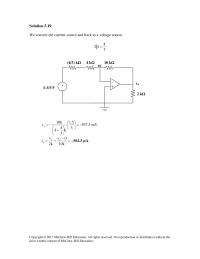
Solution 5.19 We convert the current source and back to a voltage source. 3 4 42 = (1.5/3)V + − − + vo 2 kΩ = + −= 3 […]
Chapter 6 Homework A voltage across a capacitor is equal to
Solution 6.1 ( ) =−== −− tt tee dt dv Ci 33 625.7 15(1 – 3t)e–3t A p = vi = 15(1–3t)e–3t ⋅ 2t e–3t = 30t(1 – 3t)e–6t W. 15(1 – 3t)e–3t A, 30t(1 – 3t)e–6t W Copyright © […]
Chapter 6 Homework Determine A The Total Capacitance B The
Solution 6.21 4µF in series with 12µF = (4×12)/16 = 3µF 3µF in parallel with 3µF = 6µF 6µF in series with 6µF = 3µF 3µF in parallel with 2µF = 5µF 5µF in series with 5µF = 2.5µF Hence […]
Chapter 6 Homework Figure 684 For Prob 662 Solution A
Solution 6.60 8 15 5//3== eq L ( ) tt eqo ee dt d dt di Lv 22 154 8 15 −− −=== ∫∫ −− +=−+=+= tt tt t ooo edteidttv L I i 00 22 0 5.12)15( 5 1 […]
Chapter 6 Homework from the initial condition for i needing to be 0.3 A.
Solution 6.40 10, 2 4 30 5 , 4 6 i t ms t t ms = << − << 3 3 5, 0 2 25, 0 2 5 10 0, 2 4 0, 2 4 10 […]
Chapter 6 Homework Solution 674 001 103 Sec Rc 02
Solution 6.74 RC = 0.01 x 20 x 10-3 sec secm dt dv 2.0 dt dv RCv i o−=−= <<− << <<− = 4t3,V2 3t1,V2 1t0,V2 v o Thus vo(t) is as sketched below: -2 […]
Chapter 7 Homework How Long Does Take The Voltage
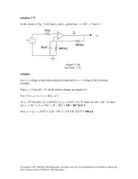
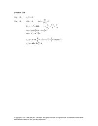
Solution 7.75 In the circuit of Fig. 7.140, find vo and io, given that vs = 10[1 – e–t]u(t) V. vo vs − + 100 kΩ 100 kΩ 10 µF − Figure 7.140 For Prob. 7.75. Solution Let va = […]
Chapter 7 Homework Let i(t) be the current through the inductor.
Solution 7.58 For t < 0, 0)t(v o = For t > 0, 10)0(i = , 5 31 20 )(i = + =∞ Ω=+= 431R th , 16 1 4 41 R L th ===τ [ ] τ ∞−+∞= t– […]
Chapter 7 Homework To find R th we replace the inductor by a 1-V voltage
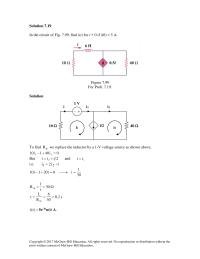
Solution 7.19 In the circuit of Fig. 7.99, find i(t) for t > 0 if i(0) = 5 A. Figure 7.99 For Prob. 7.19. Solution To find th R we replace the inductor by a 1-V voltage source as shown […]
Chapter 7 Homework where R th is the Thevenin equivalent at the capacitor
Solution 7.1 (a) τ=RC = 1/200 For the resistor, V=iR= 200 200 3 56 56 8Re 10 7 k 8 tt e x R − −− = → = = Ω 3 11 0.7143 200 200 7 10 C […]
Chapter 7 Homework where v1 is due to the 12-V source and v 2
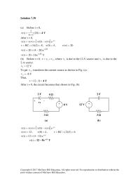
Solution 7.39 (a) Before t = 0, = + =)20( 14 )t(v V4 After t = 0, [ ] τ ∞−+∞= t– e)(v)0(v)(v)t(v 8)2)(4(RC ===τ , 4)0(v = , 20)(v =∞ 8t– e)204(20)t(v −+= =)t(v Ve1620 8t– − 1 (b) […]
Chapter 8 Homework Since I0 But 0 Which Leads
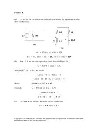
Solution 8.1 (a) At t = 0–, the circuit has reached steady state so that the equivalent circuit is shown in Figure (a). VS + − 6 Ω (a) + − v 10 H 10 µF + − vL i(0-) […]
Chapter 8 Homework Since the independent source is equal to zero until
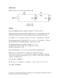
Solution 8.60 Obtain i1 and i2 for t > 0 in the circuit of Fig. 8.106. Figure 8.106 For Prob. 8.60. Solution Since the independent source is equal to zero until t = 0, i1(0) = i2(0) = 0. Applying […]
Chapter 8 Homework Since α is equal to zero, we have an undamped response
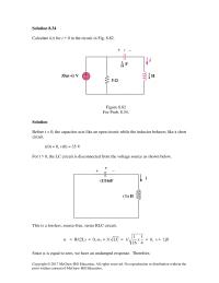
Solution 8.34 Calculate i(t) for t > 0 in the circuit in Fig. 8.82. 35u(–t) V 5 Ω Figure 8.82 For Prob. 8.34. Solution Before t = 0, the capacitor acts like an open circuit while the inductor behaves like […]
Chapter 8 Homework Under This Condition The Circuit Shown Below
Thus, v(t) = Ldi/dt = [1.323(–Asin1.323t + Bcos1.323t)e–0.5t] + [–0.5(Acos1.323t + Bsin1.323t)e–0.5t] = [1.3229(5sin1.3229t – 1.8898cos1.3229t)e–0.5t] + [(2.5cos1.3229t + 0.9449sin1.3229t)e–0.5t] v(t) = [(–0cos1.323t + 4.536sin1.323t)e–0.5t] V = [(7.559sin1.3229t)e–t/2] V. Copyright © 2017 McGraw–Hill Education. All rights reserved. No reproduction or […]
Chapter 8 Homework When the switch is off, we have a source-free parallel
Solution 8.18 When the switch is off, we have a source-free parallel RLC circuit. 5.0 2 1 ,2 125.0 11 ===== RC xLC o αω 936.125.04case dunderdampe 2 2 d=−=−=→< αωωωα oo Io(0) = i(0) = initial inductor current = […]
Chapter 8 Homework When this is saved and simulated, we obtain the initial
Solution 8.71 The schematic is shown below. We use VPWL and IPWL to model the 39 u(t) V and 13 u(t) A respectively. We set Print Step to 25 ms and Final Step to 4s in the Transient box. A […]
Chapter 9 Homework Although there are many ways to work this problem
Solution 9.1 (a) Vm = 50 V. (b) Period 220.2094 30 Ts ππ ω === = 209.4ms (c ) Frequency f = ω/(2π) = 30/(2π) = 4.775 Hz. (d) At t=1ms, v(0.01) = 50cos(30×0.01rad + 10˚) = 50cos(1.72˚ + 10˚) […]
Chapter 9 Homework Make a delta-to-wye transformation as shown in the figure below
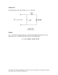
Solution 9.59 For the network in Fig. 9.66, find Zin. Let ω = 100 rad/s. Zin 100 mH 1 mF Figure 9.66 For Prob. 9.59. Solution At ω = 100 rad/s the capacitor becomes –j10 Ω and the inductor becomes […]
Chapter 9 Homework No reproduction or distribution without the prior written
Solution 9.21 (a) oooo jF 86.343236.8758.48296.690304155 ∠=+=−−∠−∠= )86.3430cos(324.8)( o ttf += (b) ooo jG 49.62565.59358.4571.2504908 −∠=−=∠+−∠= )49.62cos(565.5)( o ttg −= (c) ( ) 40,9050010 j 1 Hoo =ω−∠+∠ ω = i.e. ooo 69.1682748.125.125.0j18025.19025.0H −∠=−−=−∠+−∠= h(t) = 1.2748cos(40t – 168.69°) Copyright […]
Chapter 9 Homework The network in Fig. 9.87 is part of the schematic describing an industrial
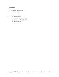
Solution 9.76 (a) 2 8sin 5 8cos(5 90 ) o vtt= = − v1 leads v2 by 70o. (b) 26sin 2 6cos(2 90 ) o vtt= = − v1 leads v2 by 180o. (c ) 1 4cos10 4cos(10 180 ) […]
Chapter 9 Homework The nodal equation will give us VC
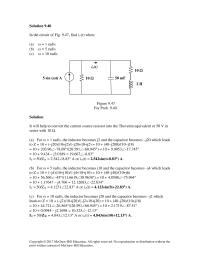
Solution 9.40 In the circuit of Fig. 9.47, find io(t) when: (a) ω = 1 rad/s (b) ω = 5 rad/s (c) ω = 10 rad/s io(t) 10 Ω 50 mF 2 H 10 Ω 5 sin (ωt) A Figure […]