Solution 7.1
(a) τ=RC = 1/200
Solution 7.2
Solution 7.3
Solution 7.4
For t<0, v(0–)=40 V.
Solution 7.5
Using Fig. 7.85, design a problem to help other students to better understand source-free
RC circuits.
Problem
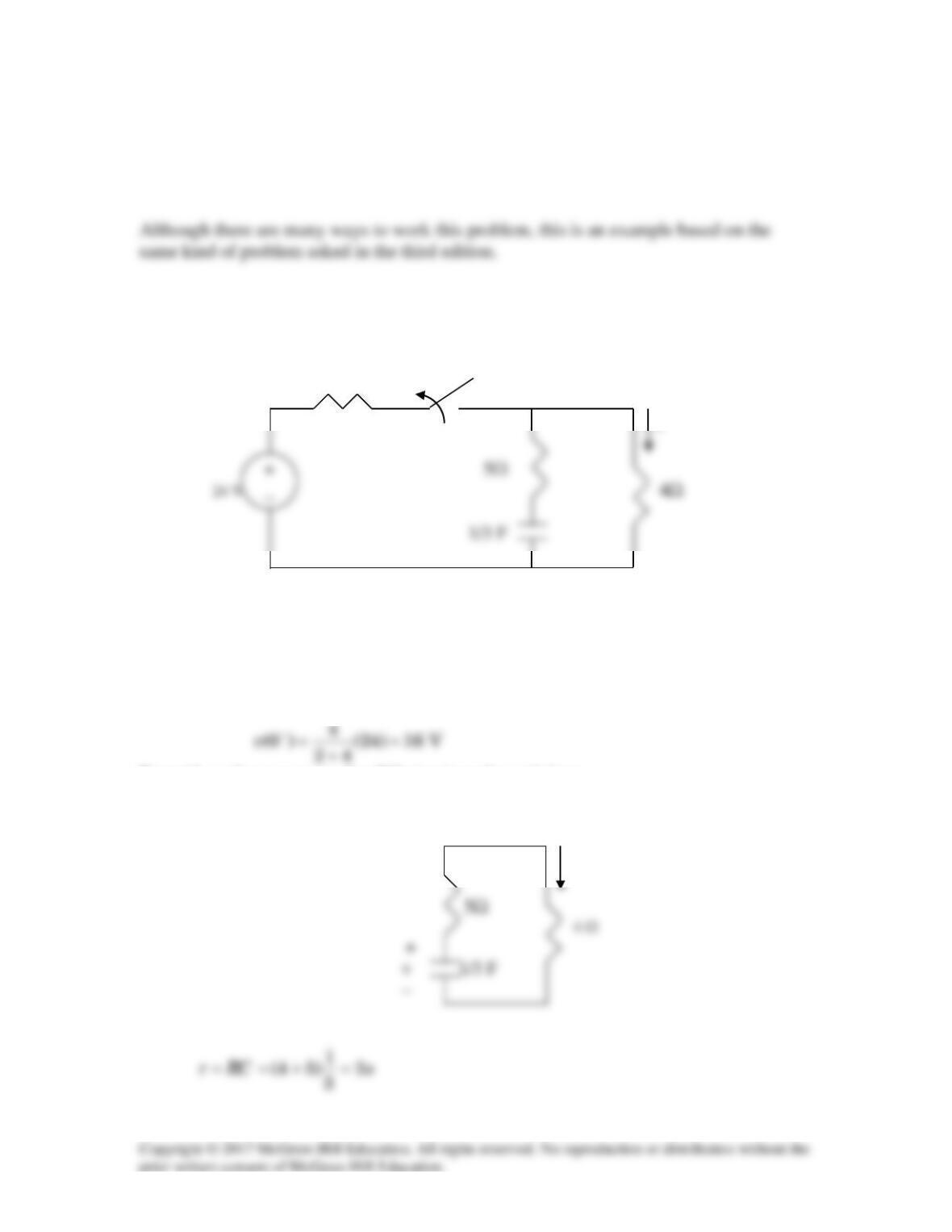
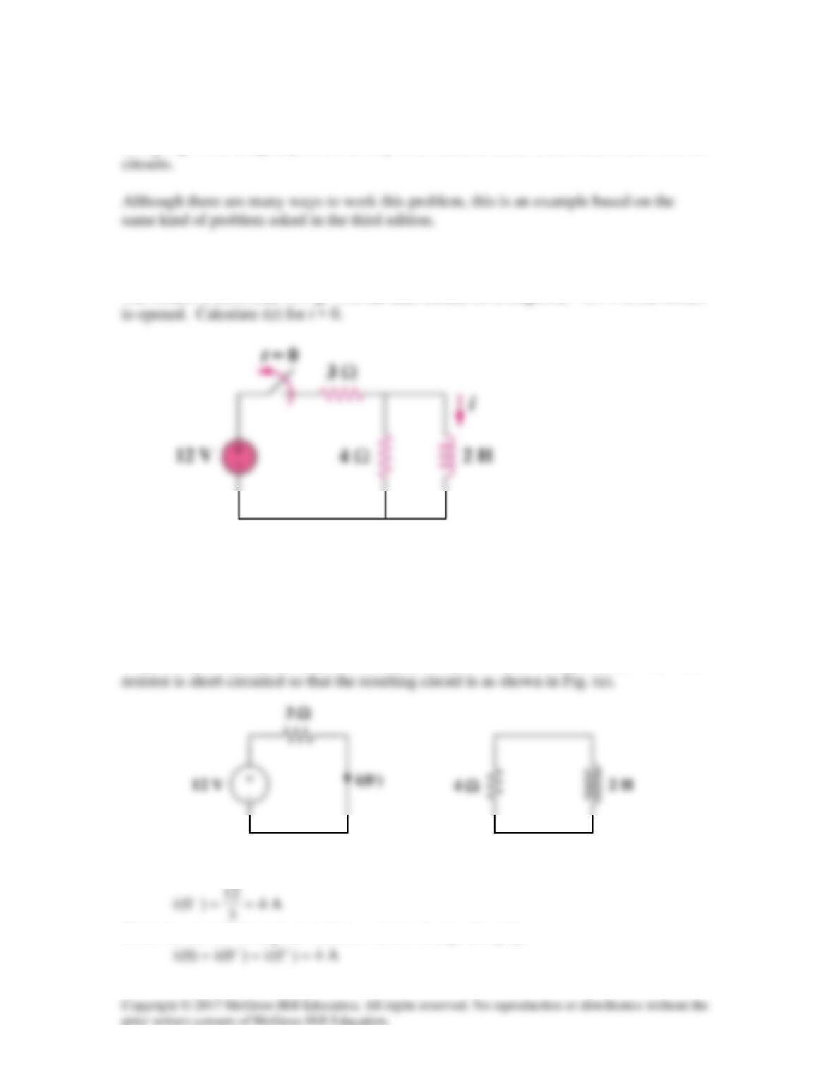
For the circuit shown in Fig. 7.85, find i(t), t>0.
2 Ω t=0
i
Figure 7.85 For Prob. 7.5.
Solution
Let v be the voltage across the capacitor. For t <0,
For t >0, we have a source-free RC circuit as shown below.
i
Solution 7.6
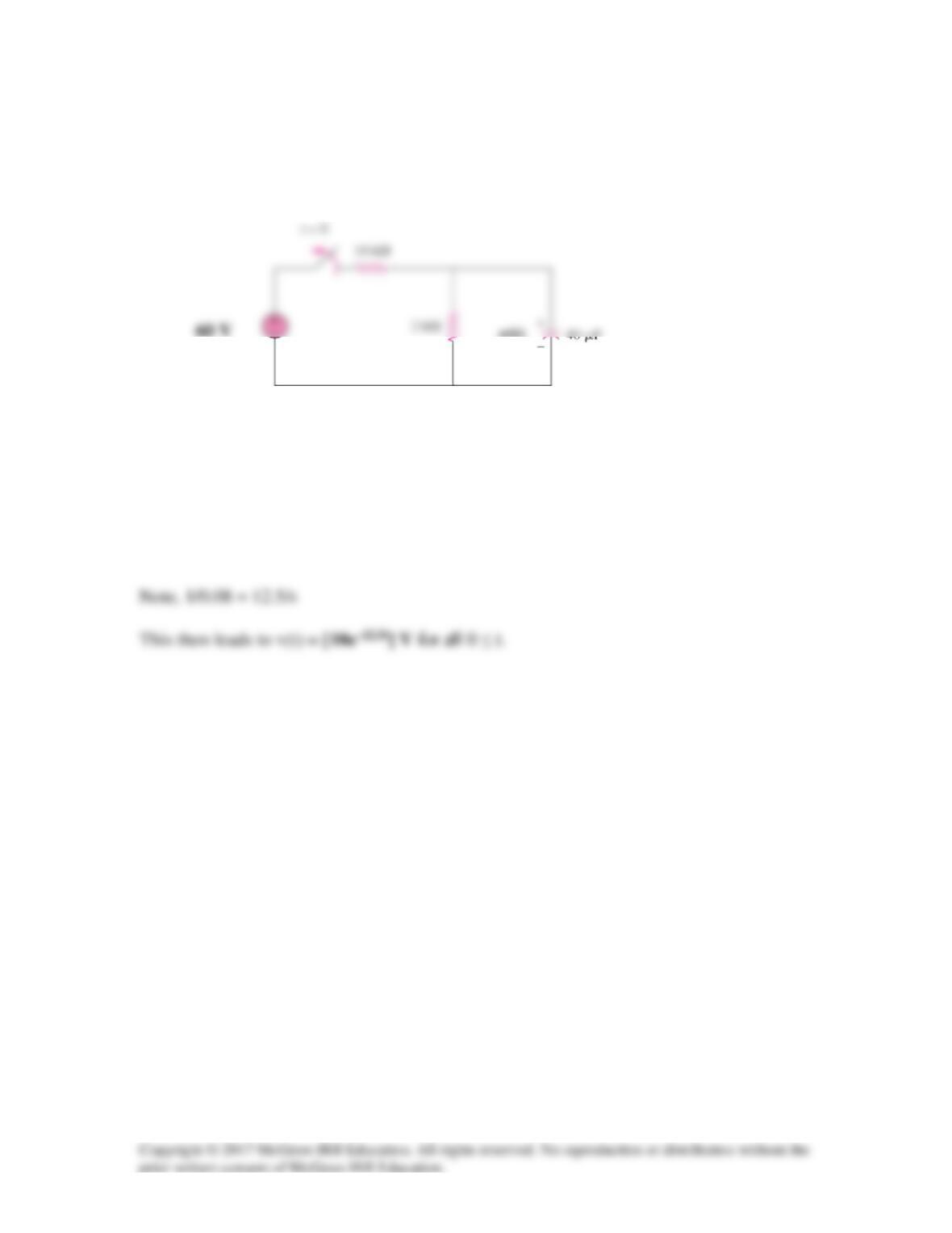
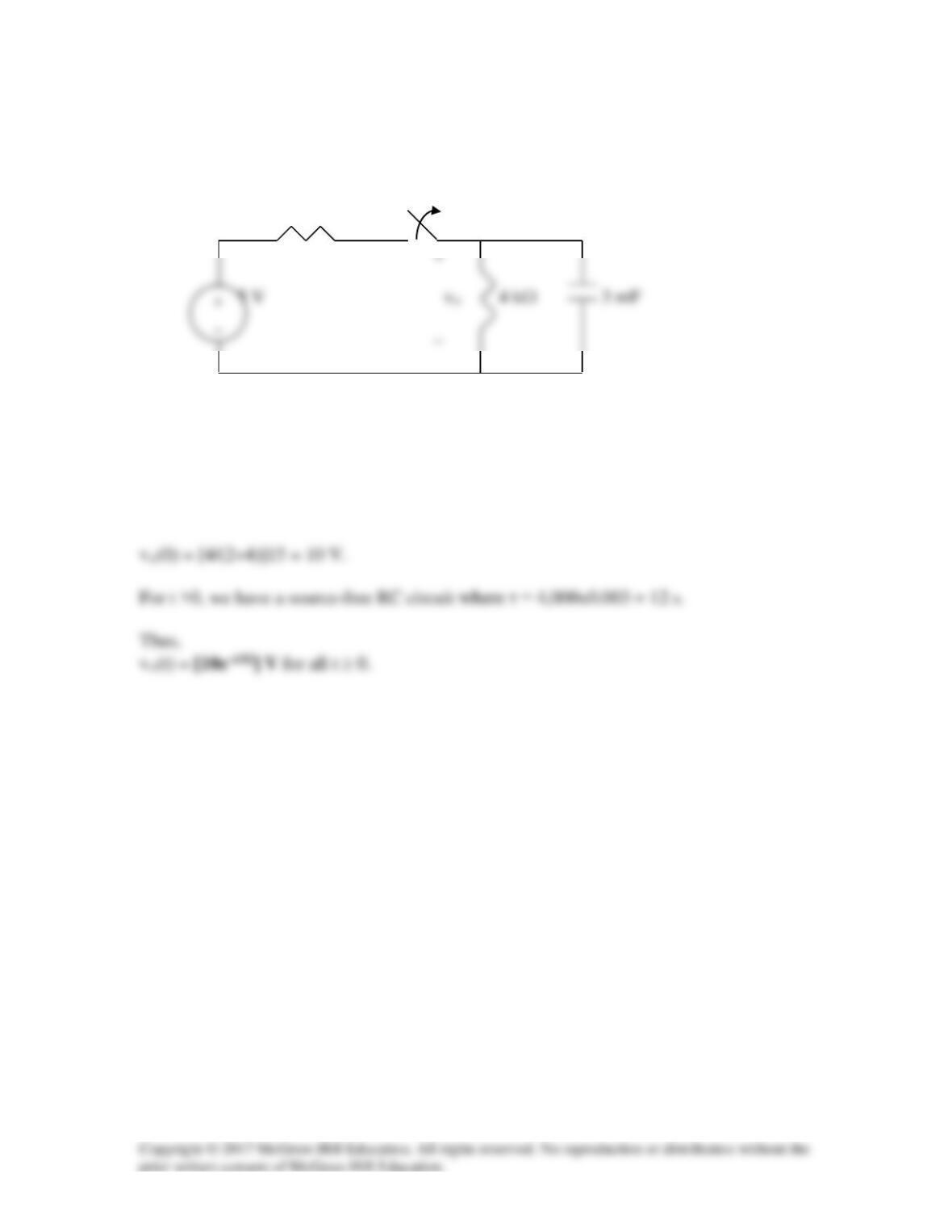
The switch in Fig. 7.85 has been closed for a long time, and it opens at t = 0. Find v(t) for
t ≥ 0.
Figure 7.85
For Prob. 7.6.
Solution
v(0) = [2×60/(10+2)] = 10 V and τ = RC = 2,000x40×10–6 = 0.08.
v(t)
Solution 7.7
Figure 7.87
For Prob. 7.7
Solution
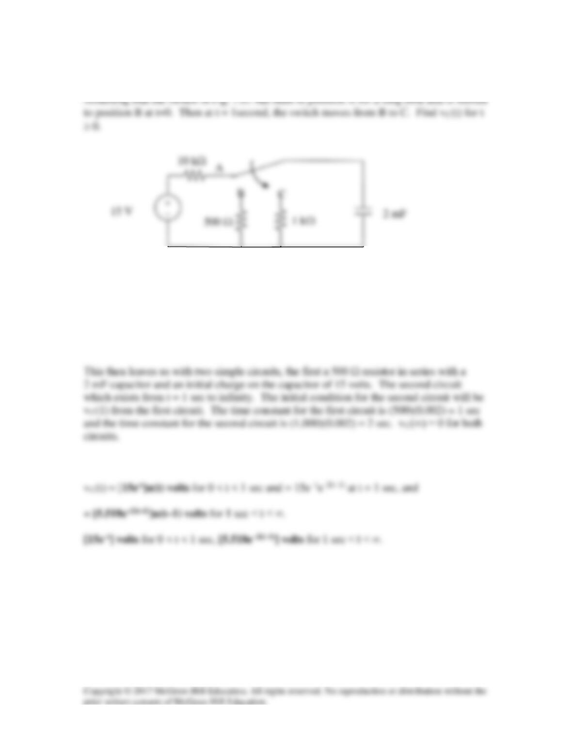
Step 1. Determine the initial voltage on the capacitor. Clearly it charges to 15 volts when
the switch is at position A because the circuit has reached steady state.
Step 2.
Solution 7.8
(a)
4
1
RC ==τ
(d)
( )
τ
−=×= 0
2t–
2
0
2
0R e1CV
2
1
CV
2
1
2
1
w
Solution 7.9
The switch in Fig. 7.89 opens at t=0. Find vo for t > 0.
2 kΩ t=0
Figure 7.89
For Prob. 7.9.
Solution
For t < 0, the switch is closed so that
Solution 7.10
For t<0,
3
(0 ) (36 ) 9 V
vV
−= =
Solution 7.11
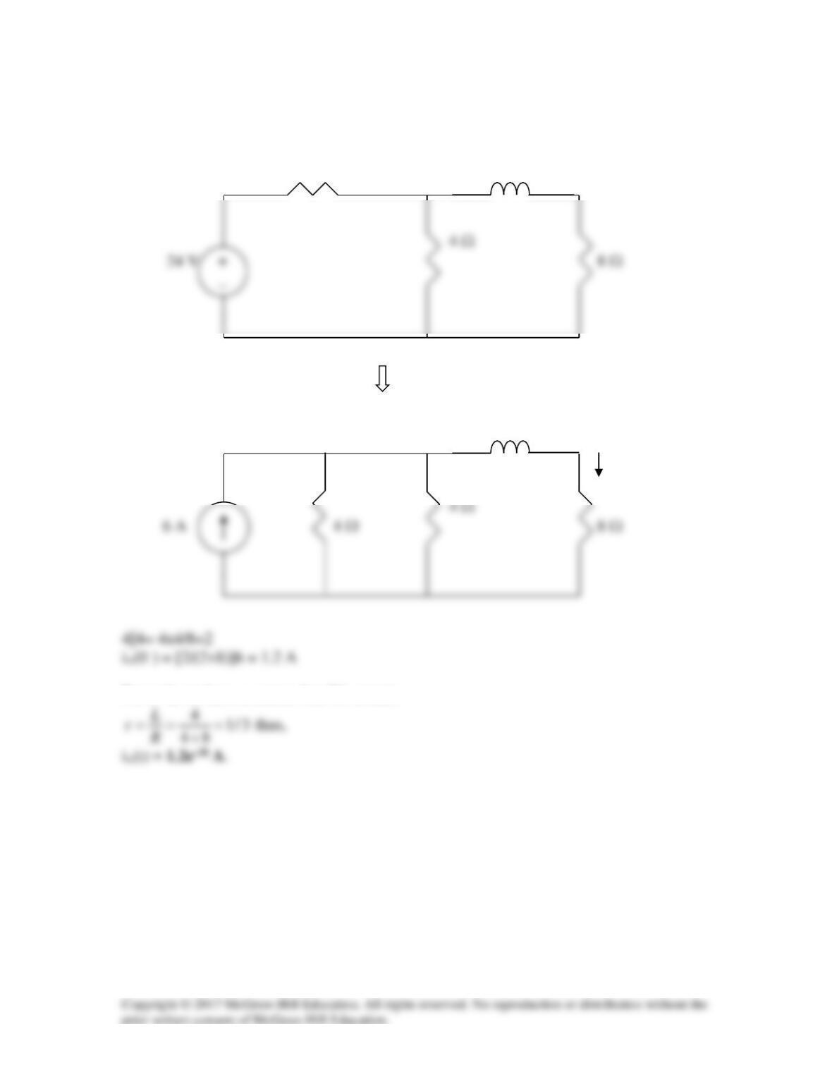
For t<0, we have the circuit shown below.
4 Ω 4H
4H
io
For t >0, we have a source-free RL circuit.
Solution 7.12
Using Fig. 7.92, design a problem to help other students better understand source-free RL
Problem
The switch in the circuit in Fig. 7.90 has been closed for a long time. At t = 0, the switch
Figure 7.90
Solution
When t < 0, the switch is closed and the inductor acts like a short circuit to dc. The 4 Ω
Since the current through an inductor cannot change abruptly,
(b)
(a)
When t > 0, the voltage source is cut off and we have the RL circuit in Fig. (b).
Solution 7.13
(a)
τ
= =
3
11
10
m s
= 1 ms.
(b) The energy dissipated in the resistor is
Solution 7.14
Solution 7.15
Solution 7.16
eq
eq
R
L
=τ
Solution 7.17
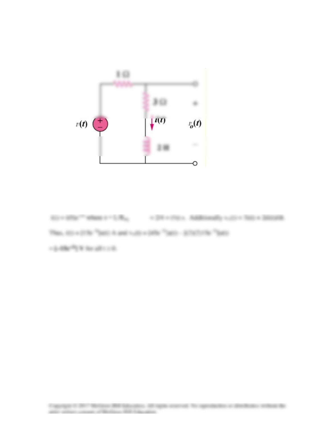
Consider the circuit of Fig. 7.97. Find v0(t) if i(0) = 15 A and v(t) = 0.
Figure 7.97
For Prob. 7.17.
Solution
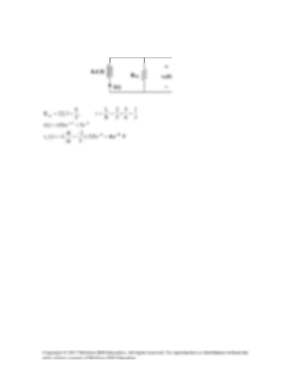
Solution 7.18
If
0)t(v =
, the circuit can be redrawn as shown below.