2R
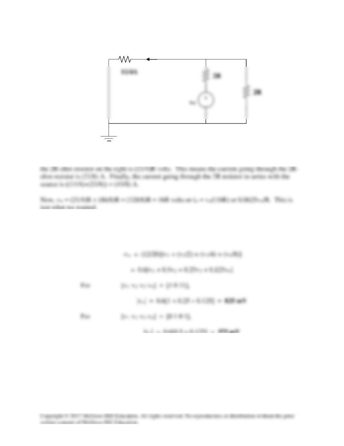
Since the current through the equivalent 21R/11-ohm resistor is (11/4) amps, the voltage across
just what we wanted.
(b) If Rf = 12 k ohms and R = 10 k ohms,
|vo| = 0.6[0.5 + 0.125] = 375 mV
21R/11
Solution 5.85
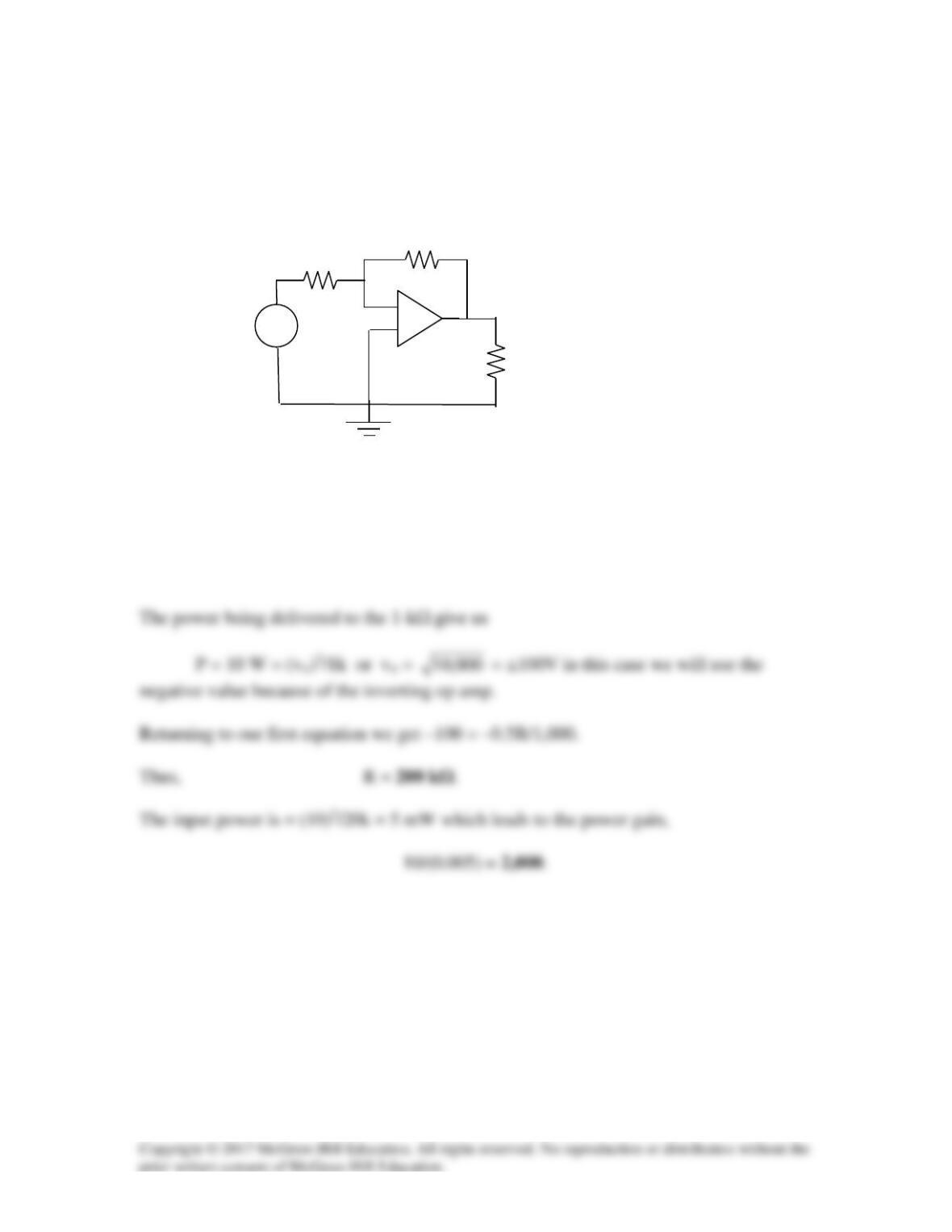
In the op amp circuit of Fig. 5.104, find the value of R so that the power absorbed by the
1-kΩ resistor is 10 W. Determine the power gain.
Figure 5.104
For Prob. 5.85.
Solution
This is an inverting amplifier. vo = –(R/20k)10 = –0.5R/1,000
1 kΩ
R
20 kΩ
−
+
10 V
+
−
Solution 5.86
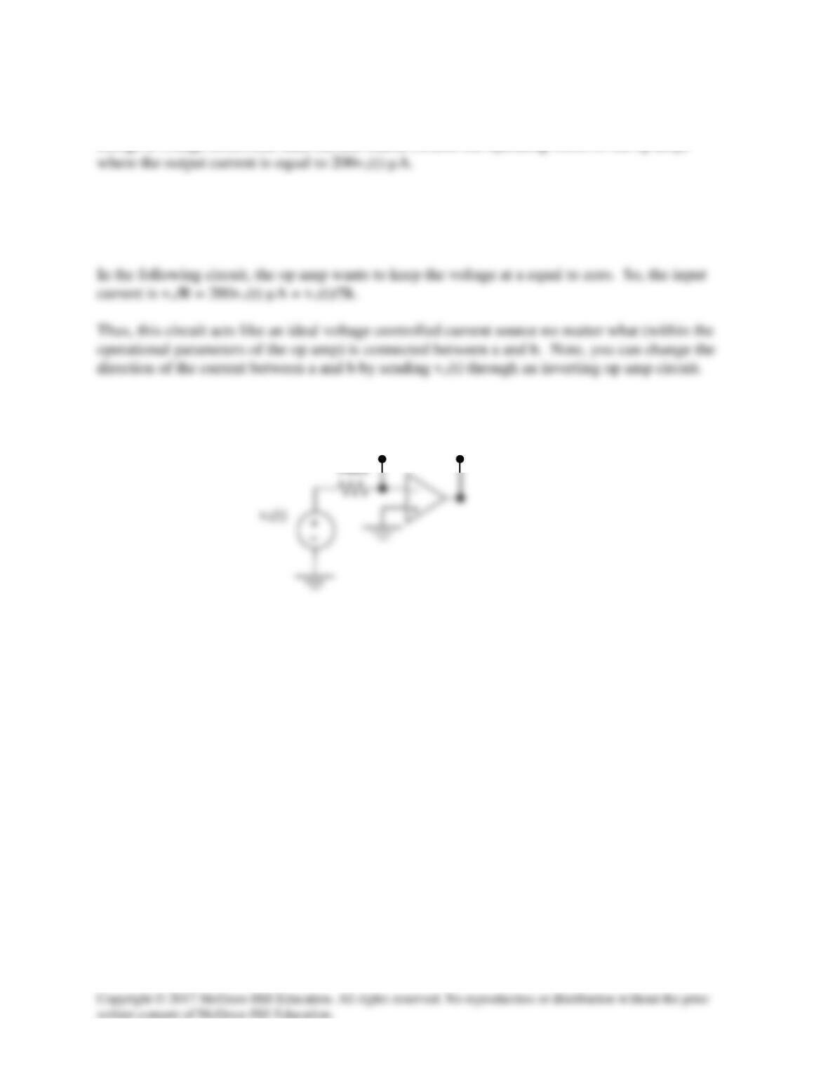
Design a voltage controlled ideal current source (within the operating limits of the op amp)
The easiest way to solve this problem is to understand that the op amp creates an output voltage
so that the current through the feedback resistor remains equal to the input current.
5kΩ
b
a
Solution 5.87
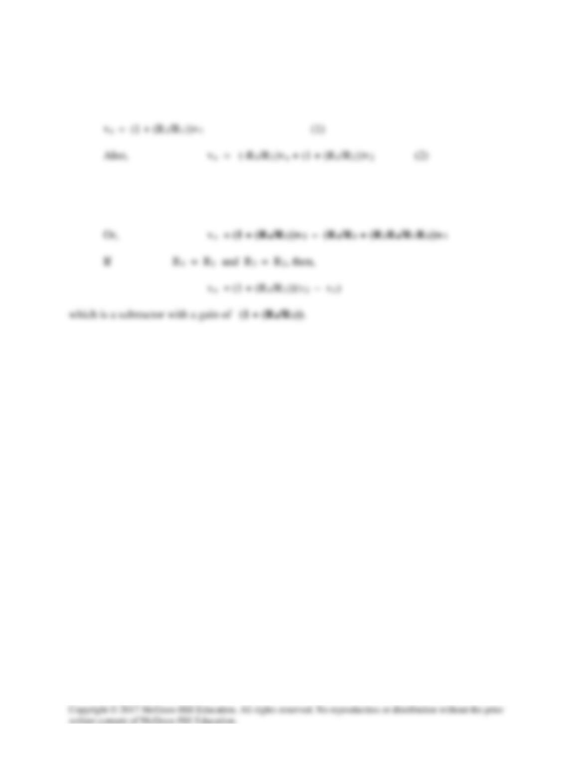
The output, va, of the first op amp is,
Substituting (1) into (2),
vo = (-R4/R3) (1 + (R2/R1))v1 + (1 + (R4/R3))v2
Solution 5.88
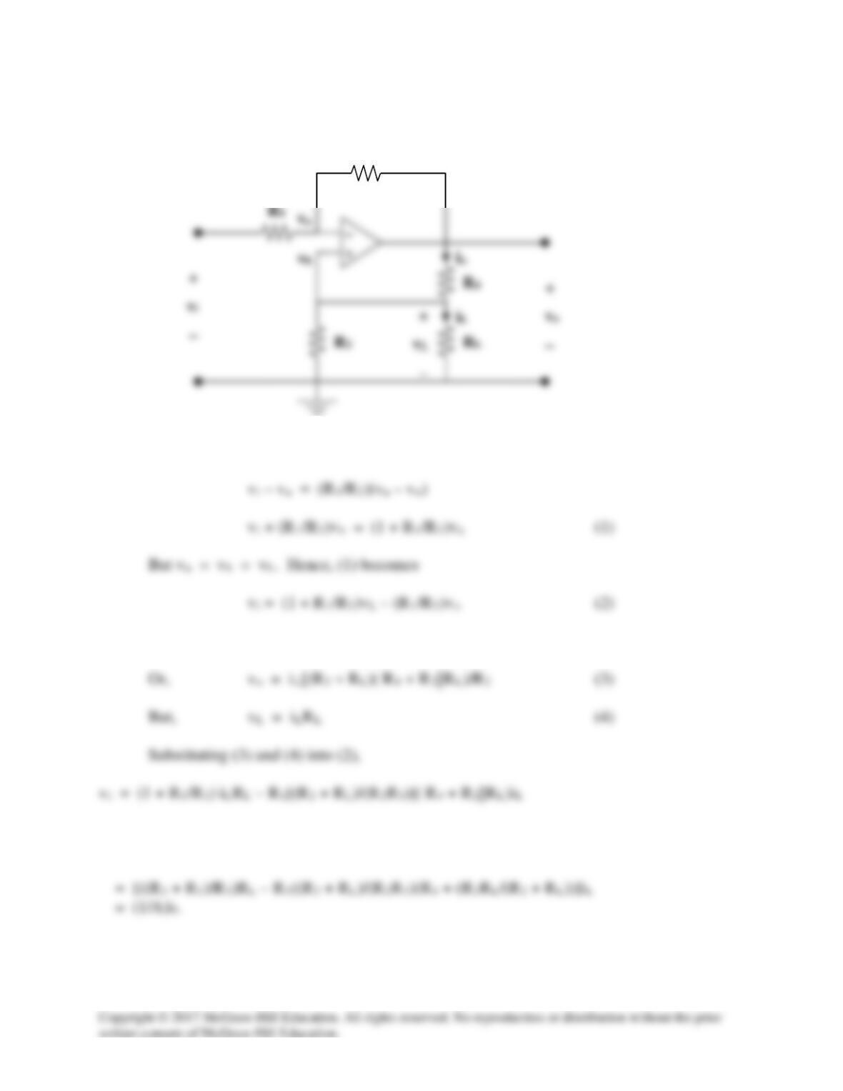
We need to find VTh at terminals a – b, from this,
Now we use Fig. (b) to find VTh in terms of vi.
a
a
b
(a)
b
(b)
Solution 5.89
Solution 5.90
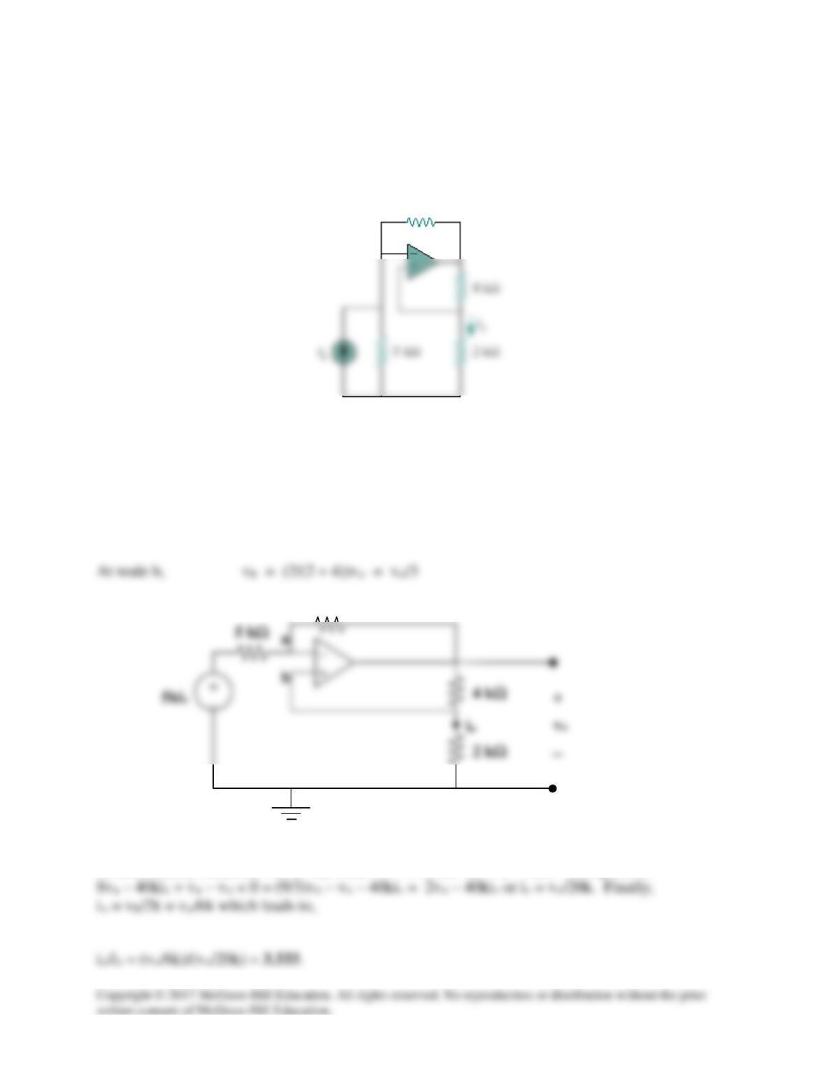
The op amp circuit in Fig. 5.107 is a current amplifier. Find the current gain io/is of the
amplifier.
Figure 5.107
For Prob. 5.90.
Solution
Transforming the current source to a voltage source produces the circuit below,
At node a, [(va–5kis)/5k] + [(va–vo)/40k] + 0 = 0 where va = vb = vo/3. This gives us
40 kΩ
40 kΩ
Solution 5.91
R1 and R2 have the same voltage, vo, across them.
Substituting (2) and (3) into (1) gives,
Solution 5.92
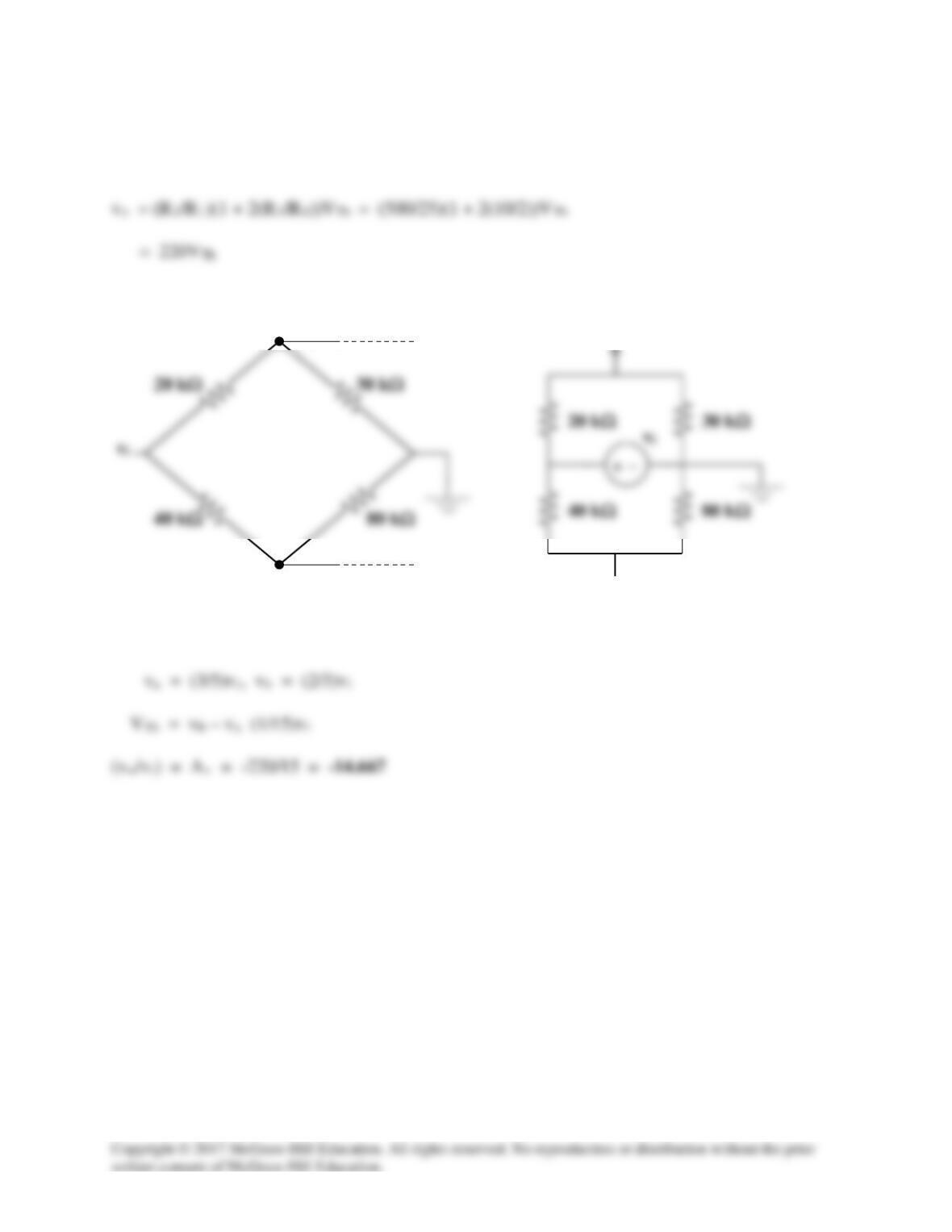
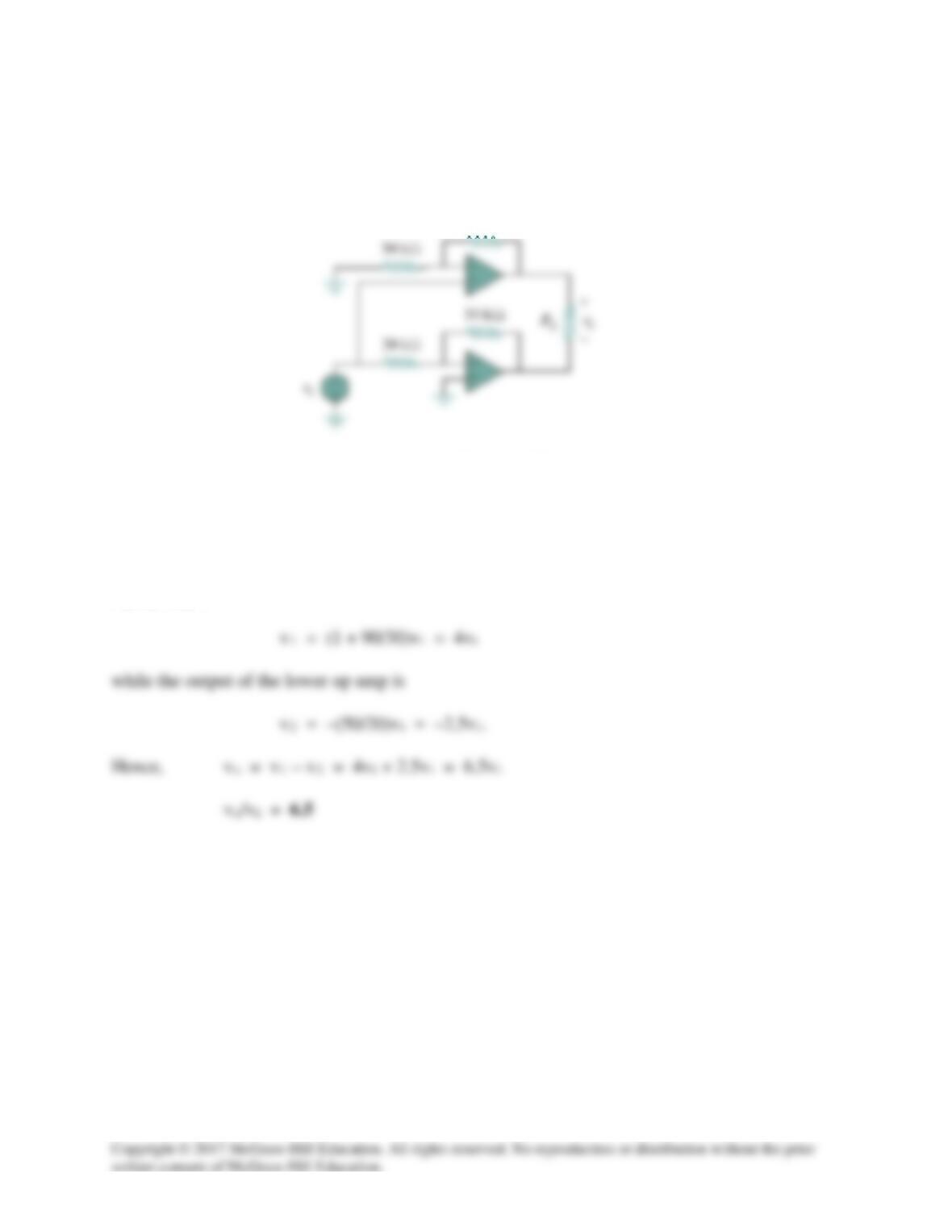
Refer to the bridge amplifier shown in Fig. 5.109. Determine the voltage gain vo/vi .
Figure 5.109
For Prob. 5.92.
Solution
The top op amp circuit is a non-inverter, while the lower one is an inverter. The output at the
top op amp is
90 kΩ
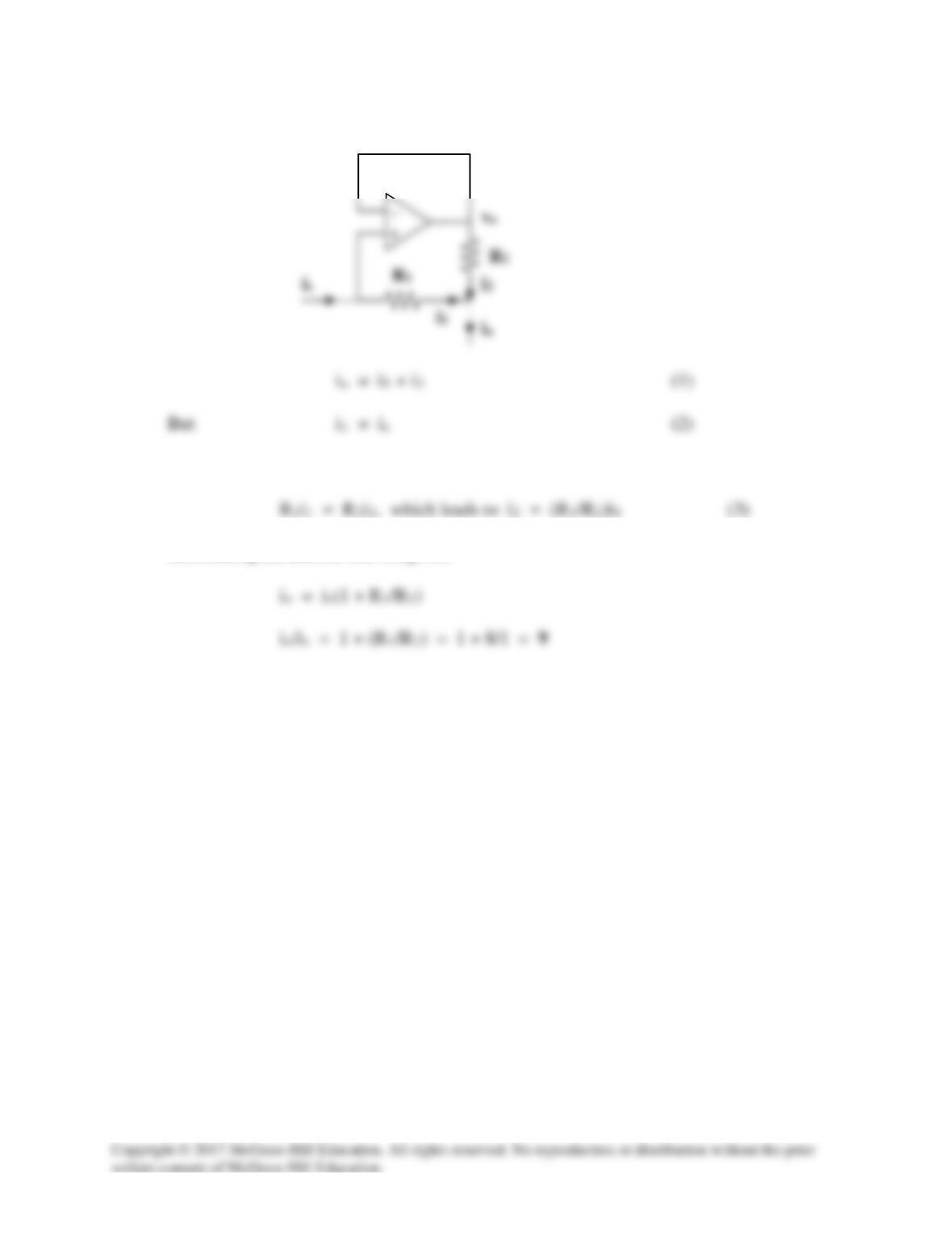
Solution 5.93
R1
At node a, (vi – va)/R1 = (va – vo)/R3
io = vo/(R4 + R2||RL), iL = (R2/(R2 + RL))io = (R2/(R2 + RL))(vo/( R4 + R2||RL))
R3
Thus,