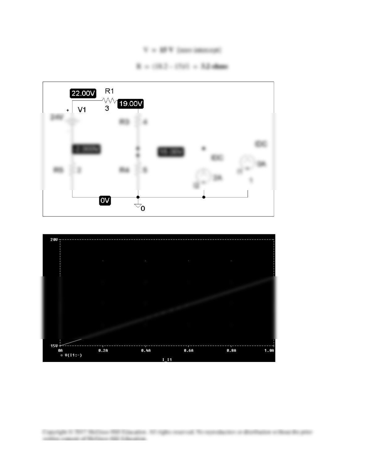
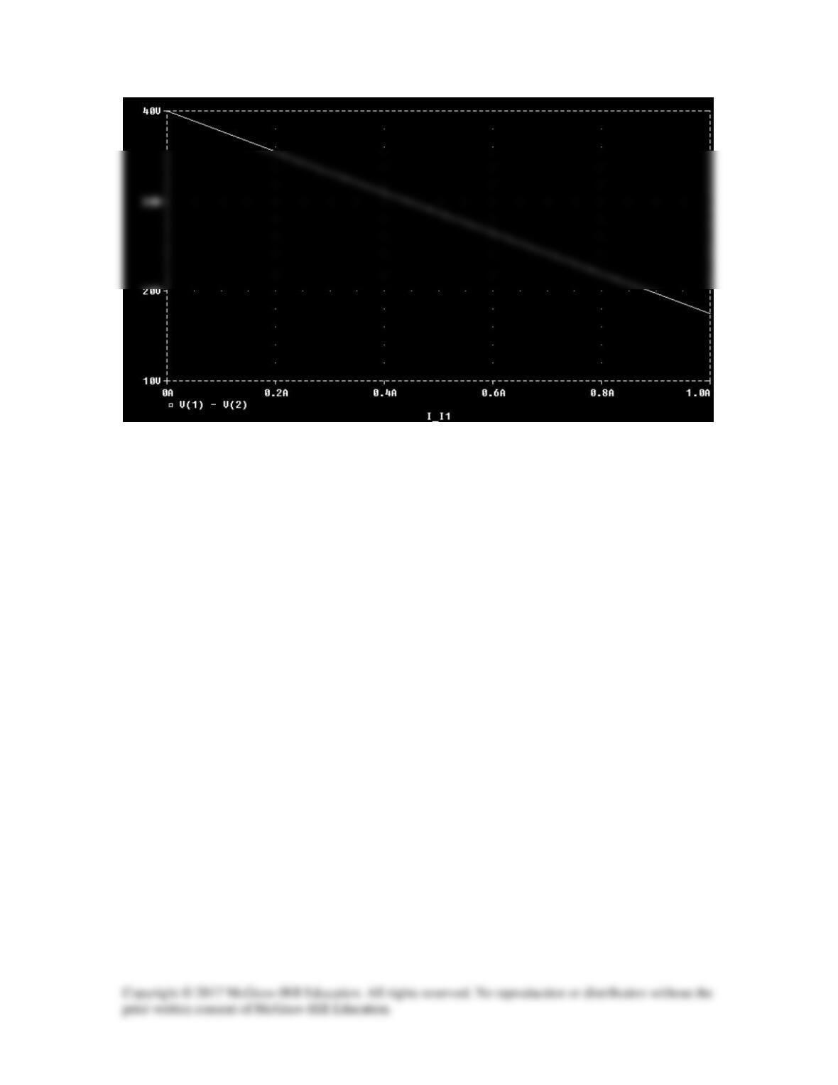
Solution 4.78
The schematic is shown below. We perform a dc sweep on the current source, I1,
connected between terminals a and b. The plot is shown. From the plot we obtain,
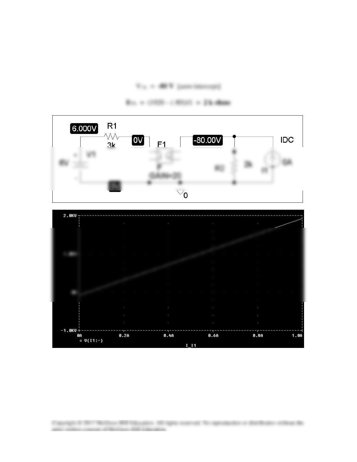
Solution 4.79
After drawing and saving the schematic as shown below, we perform a dc sweep on I1
connected across a and b. The plot is shown. From the plot, we get,
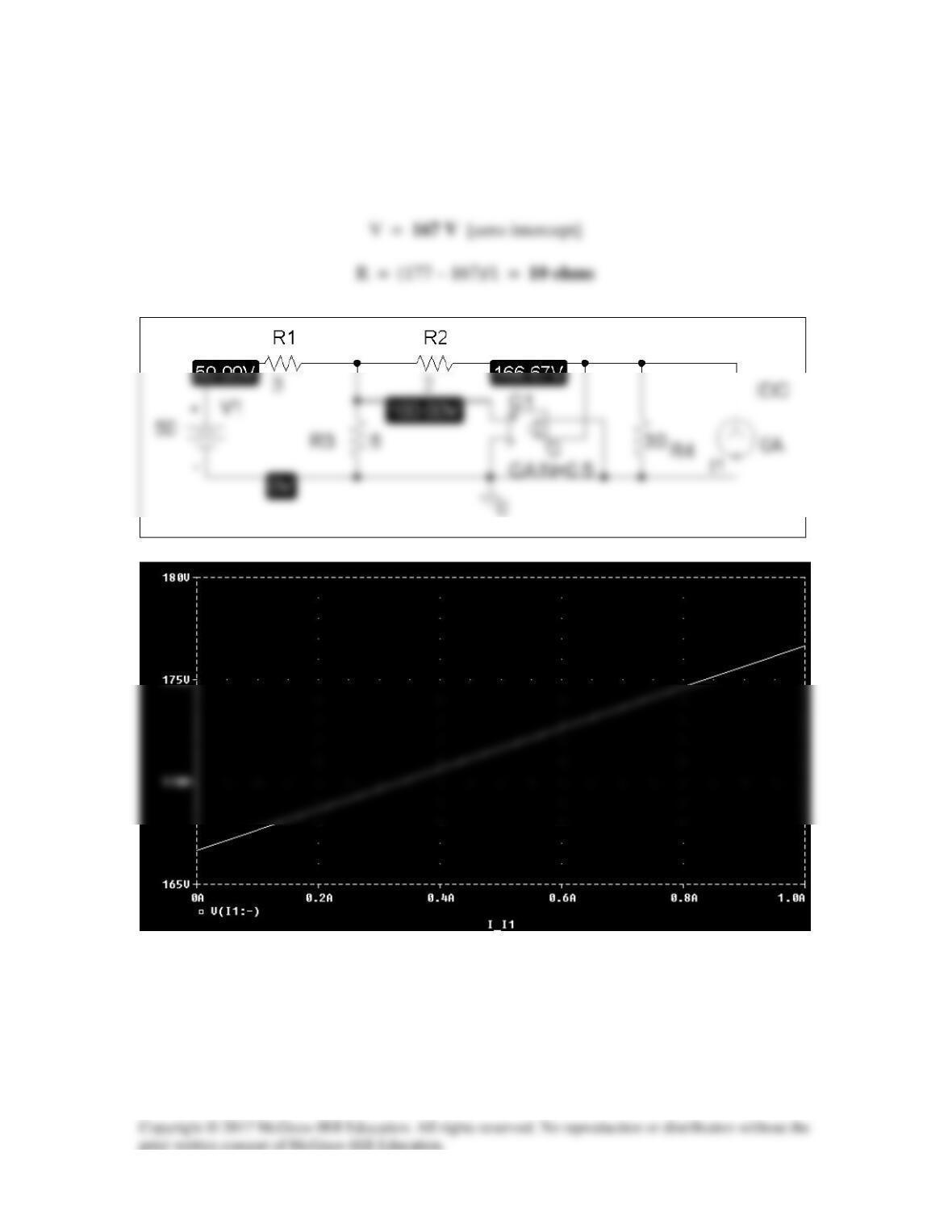
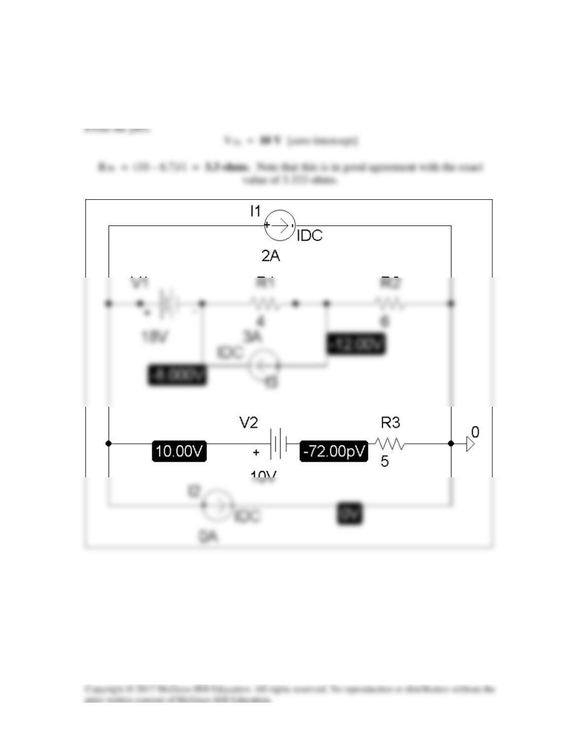
Solution 4.80
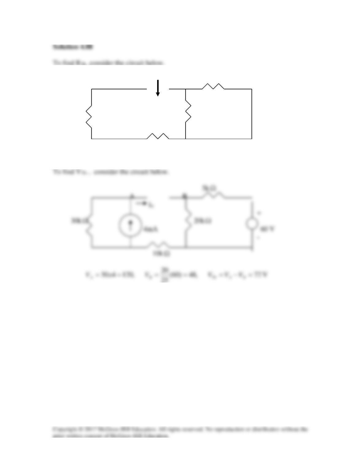
The schematic in shown below. We label nodes a and b as 1 and 2 respectively. We
perform dc sweep on I1. In the Trace/Add menu, type v(1) – v(2) which will result in the
plot below. From the plot,
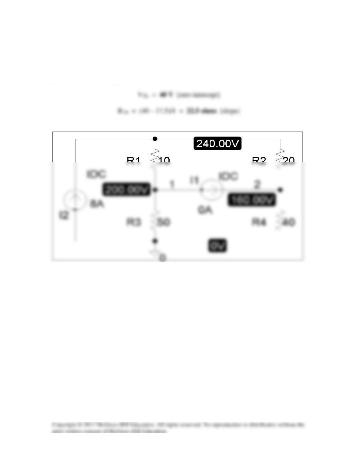
Solution 4.81
The schematic is shown below. We perform a dc sweep on the current source, I2,
connected between terminals a and b. The plot of the voltage across I2 is shown below.
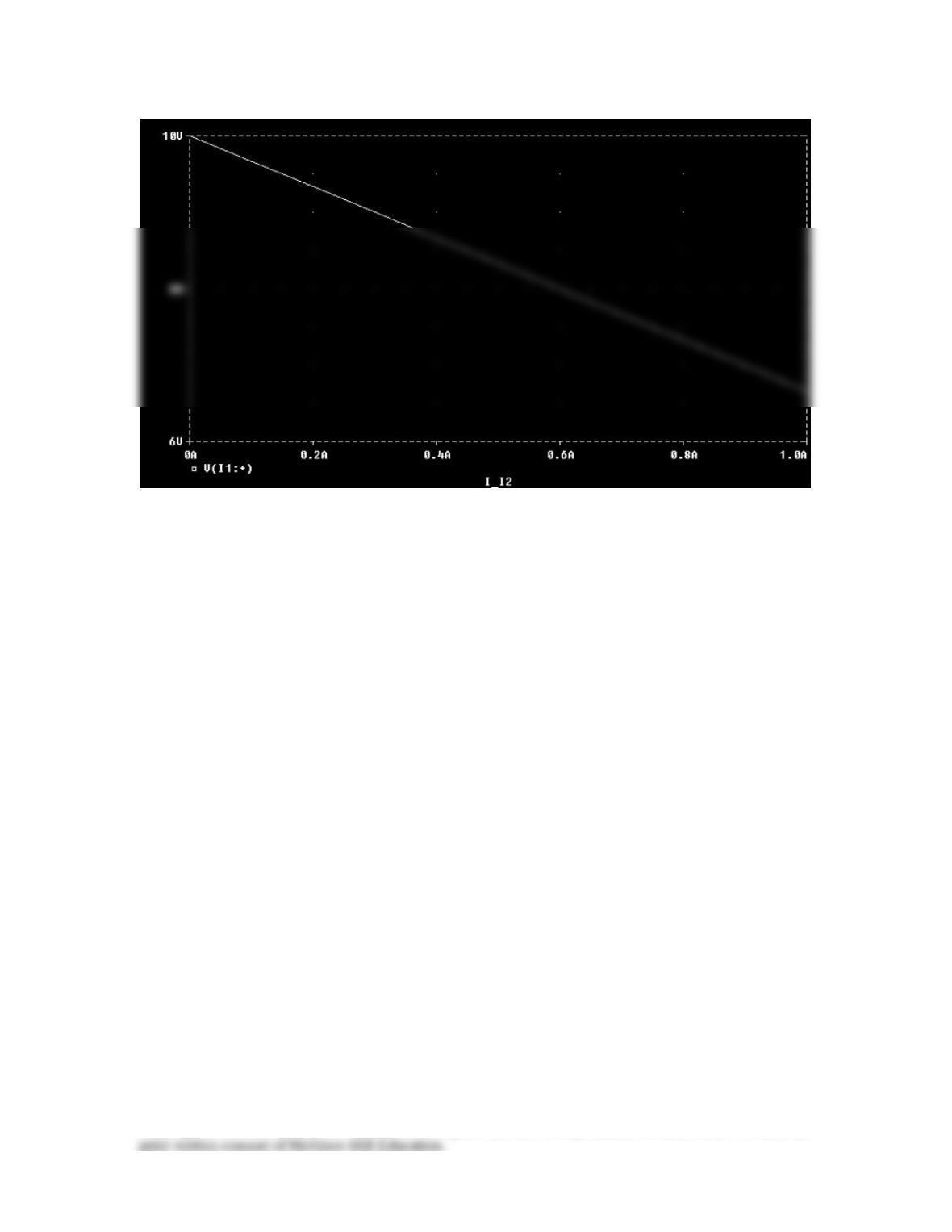
Copyright © 2017 McGraw–Hill Education. All rights reserved. No reproduction or distribution without the

Solution 4.82
An automobile battery has an open circuit voltage of 14.7 volts which drops to 12 volts
when connected to two 65 watt headlights. What is the resistance of each headlight and
the value of the internal resistance of the battery?
Step 1. Basically we can treat this like a Thevenin equivalent circuit problem.

Solution 4.83
The following results were obtained from measurements taken between the two terminals
of a resistive network.
Solution
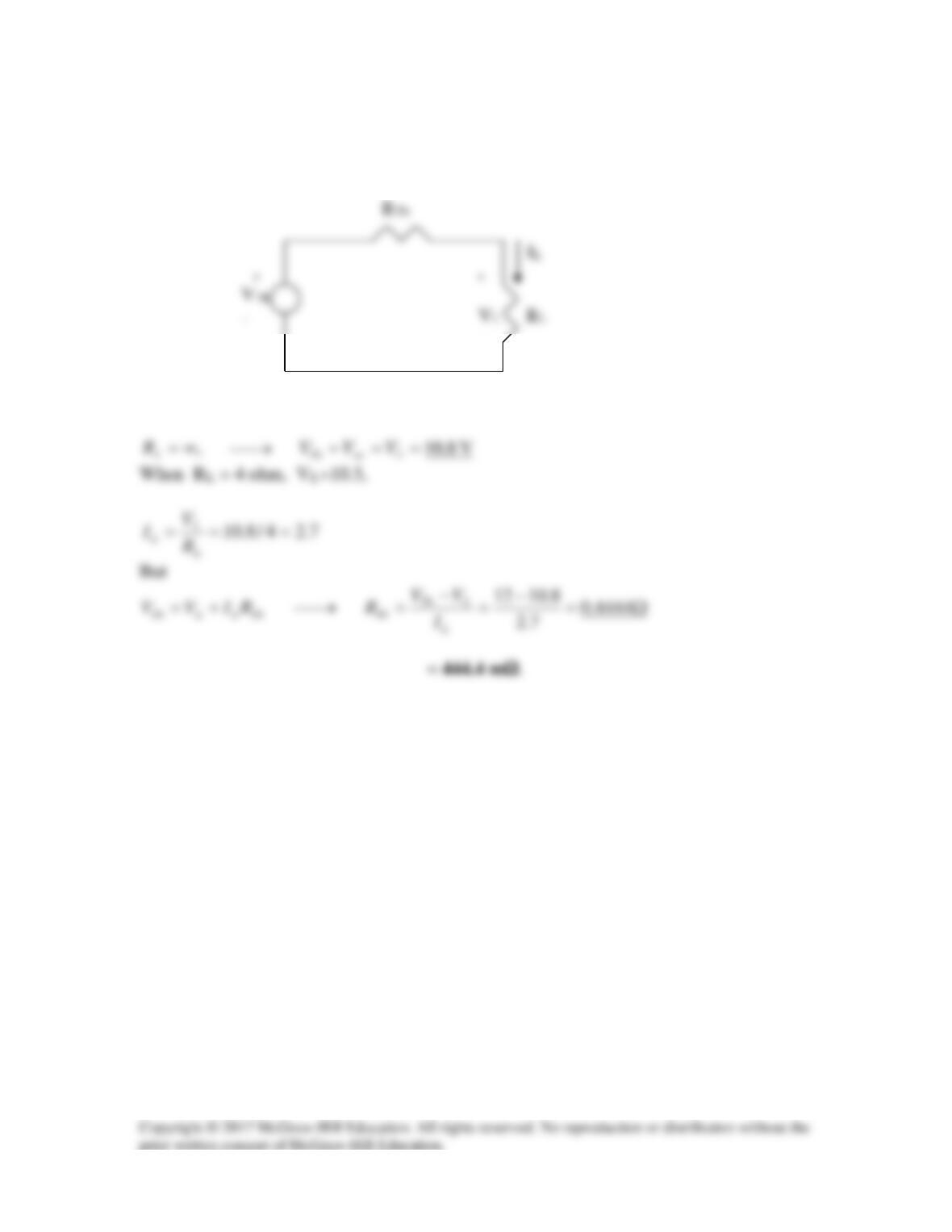
Solution 4.84
Let the equivalent circuit of the battery terminated by a load be as shown below.
–
For open circuit,
Solution 4.85
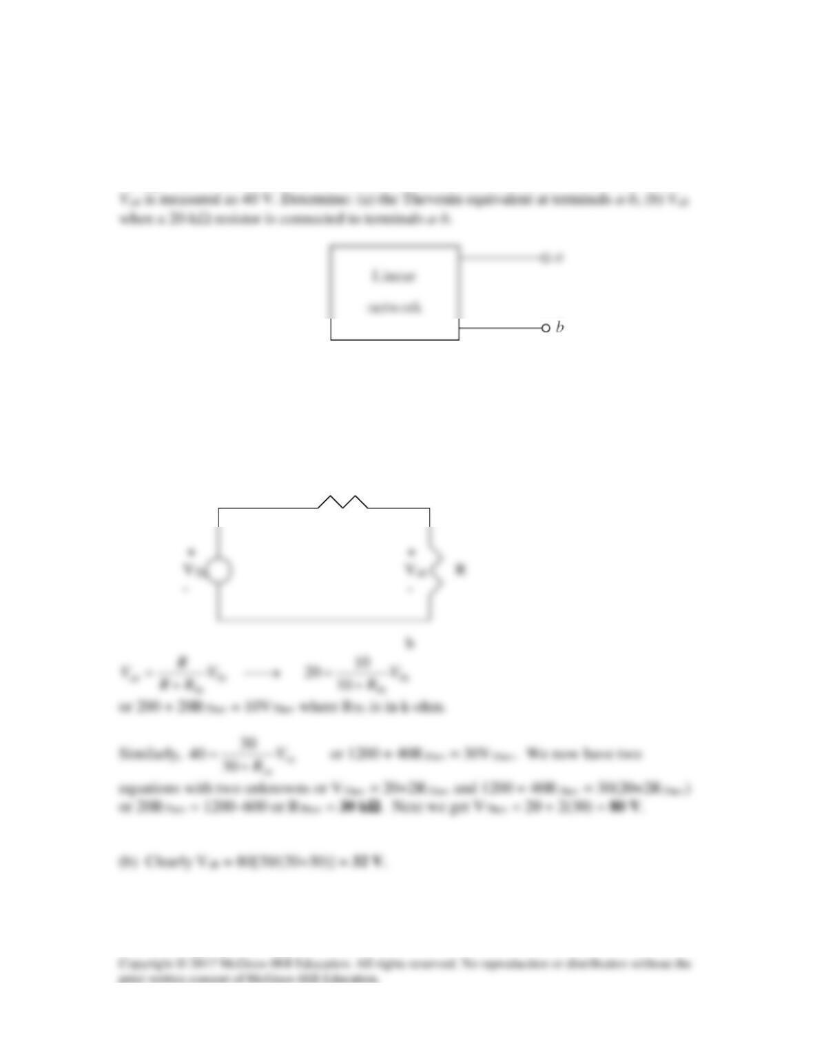
The Thevenin equivalent at terminals a–b of the linear network shown in Fig. 4.142 is to
be determined by measurement. When a 10-kΩ resistor is connected to terminals a–b, the
voltage Vab is measured as 20 V. When a 30-kΩ resistor is connected to the terminals,
Figure 4.142
For Prob. 4.85.
Solution
(a) Consider the equivalent circuit terminated with R as shown below.
RTh
a
Solution 4.86
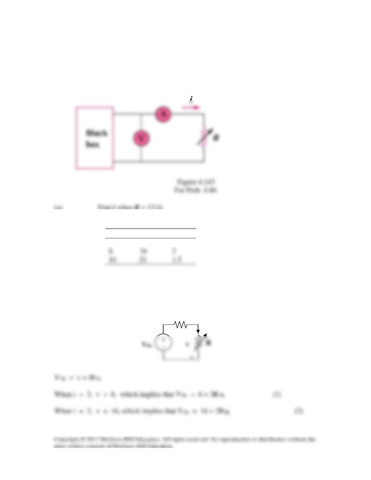
A black box with a circuit in it is connected to a variable resistor. An ideal ammeter (with
zero resistance) and an ideal voltmeter (with infinite resistance) are used to measure
current and voltage as shown in Fig. 4.143. The results are shown in the table below.
(a) Find i when R = 12 Ω.
(b) Determine the maximum power from the box.
R(Ω)
V(V)
i(A)
2
6
3
8
16
2
14
21
1.5
Solution
Step 1. We replace the box with the Thevenin equivalent.
R
Th
i
+

Step 2. From (1) – (2), we get 0 = –10 + RThev or RThev = 10 Ω and VThev = 6+30
or 36 V. It is interesting to note that we really only need the two data points, the
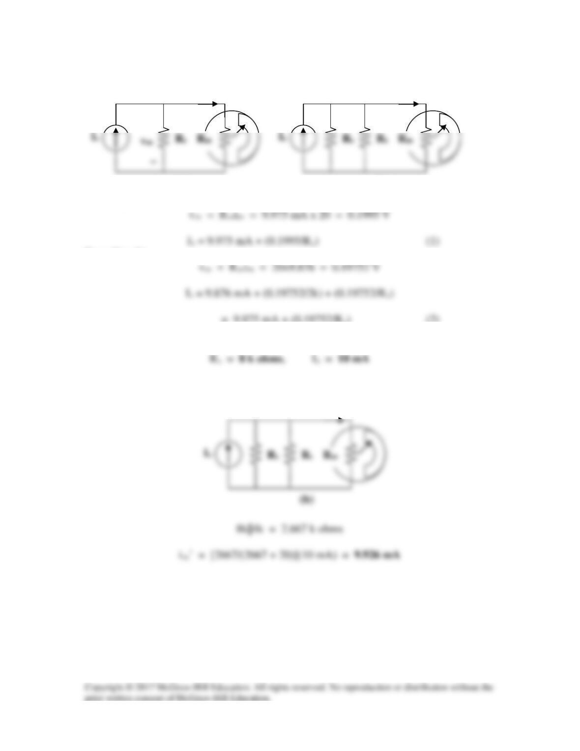
Solution 4.87
(a)
From Fig. (a),
From Fig. (b),
= 9.975 mA + (0.19752/Rs) (2)
Solving (1) and (2) gives,
(b)
im’ = 9.876 mA
(a)
+
im = 9.975 mA
(b)
im = 9.876 mA
RTh 5k
Ω
A B
30k
Ω
20k
Ω
10k
Ω
Ω=++= kRTh 445//201030
Ω
Ω
Ω
Ω