Solution 8.60
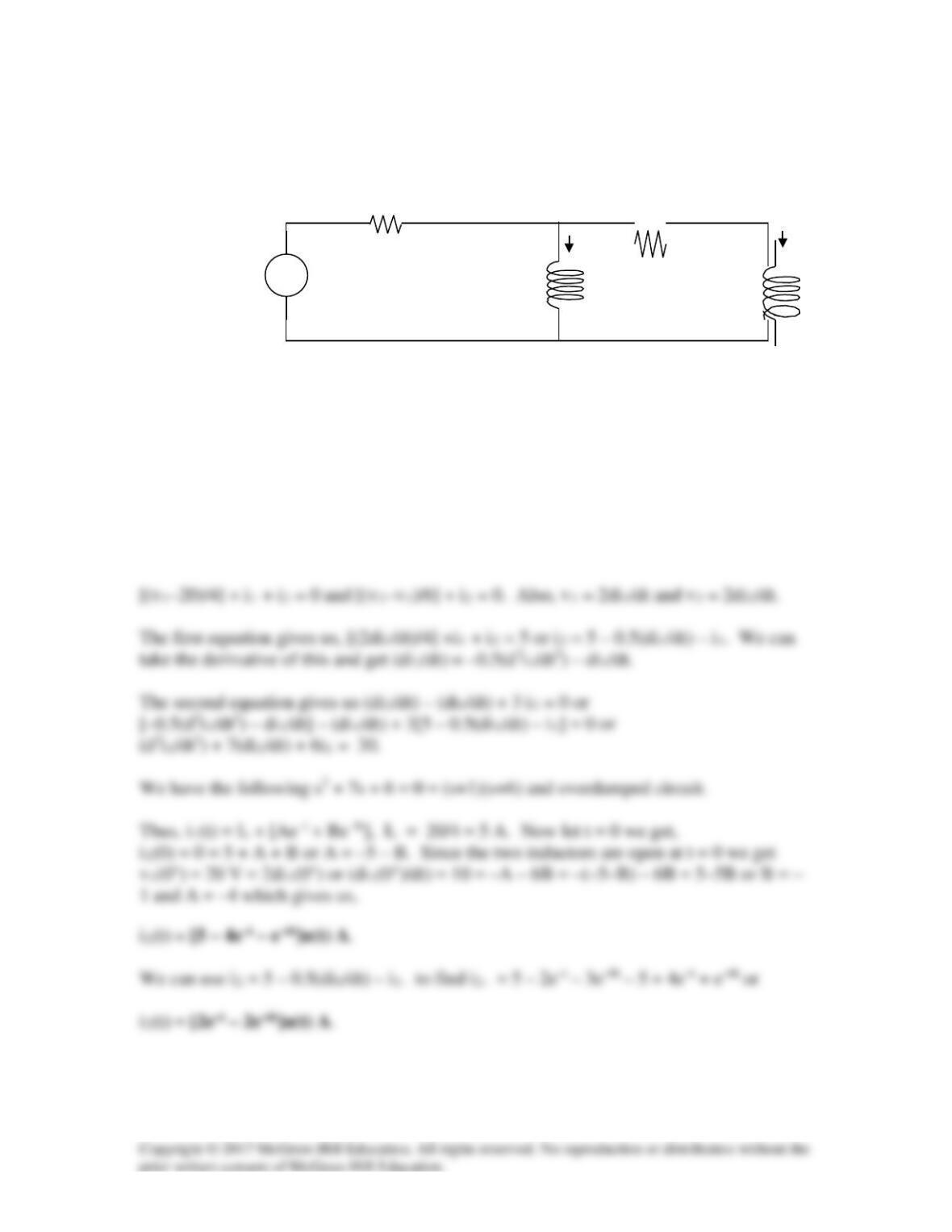
Obtain i1 and i2 for t > 0 in the circuit of Fig. 8.106.
Figure 8.106
For Prob. 8.60.
Solution
Since the independent source is equal to zero until t = 0, i1(0) = i2(0) = 0.
Applying nodal analysis and letting the voltage at node 1 be v1 (the voltage across the
first inductor) and at node 2 be v2 (the voltage across the second inductor) we get,
i2
i1
2 H
20u(t) V
+
−
4 Ω
6 Ω
2 H
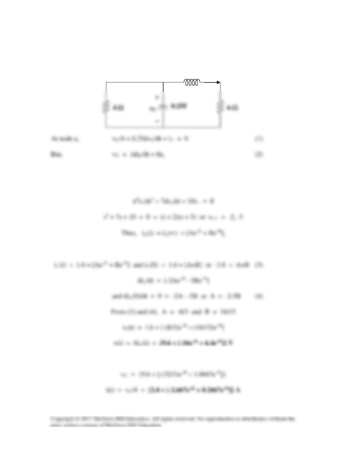
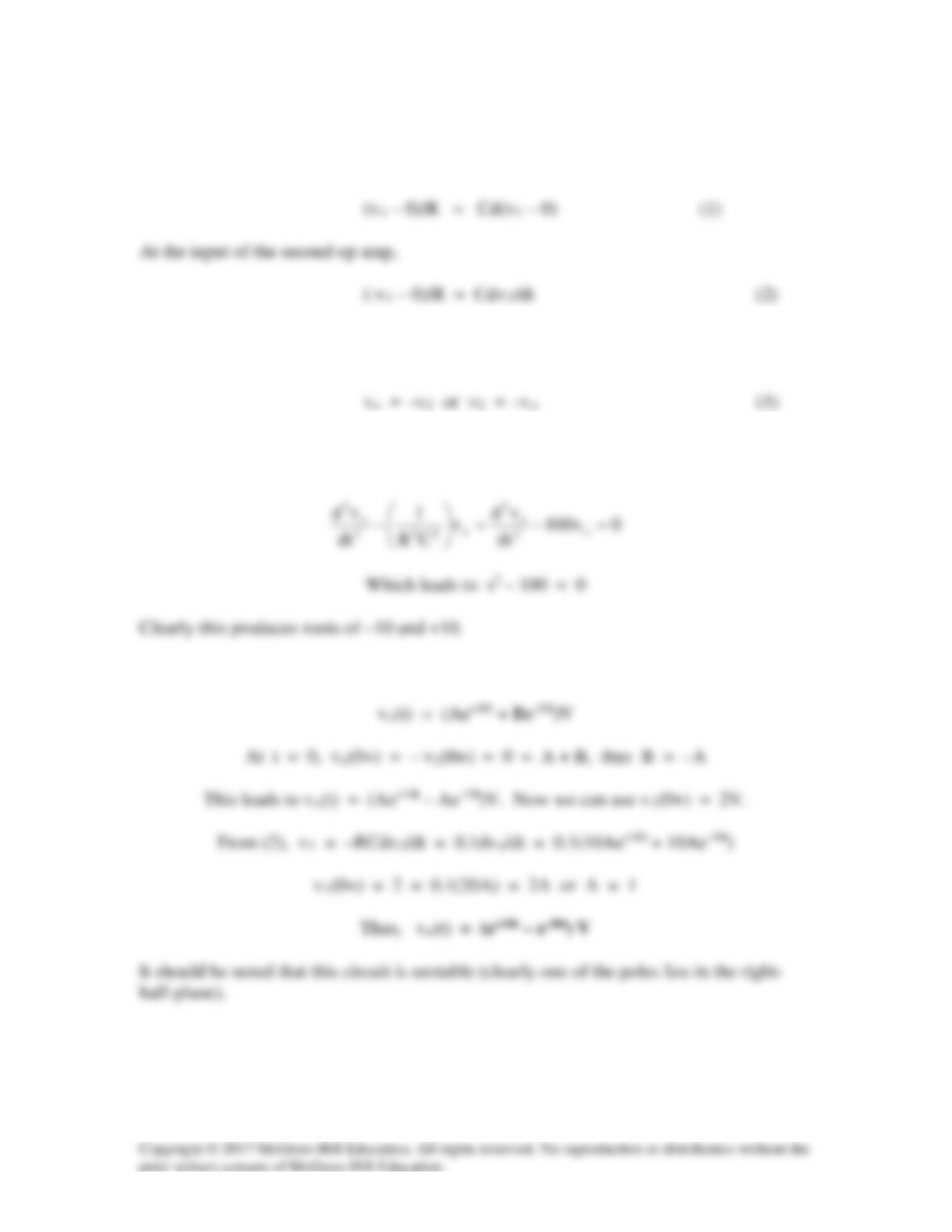
Solution 8.61
For t > 0, we obtain the natural response by considering the circuit below.
Combining (1) and (2),
(1/4)diL/dt + (6/4)iL + 0.25d2iL/dt2 + (6/4)diL/dt + iL = 0
where iL(∞) represents the final inductor current = 4(4)/(4 + 6) = 1.6
vC = 1diL/dt + 6iL = [ (16/3)e–2t – (16/3)e–5t] + {9.6 + [-16e–2t + 6.4e–5t]}
iL
a
1 H
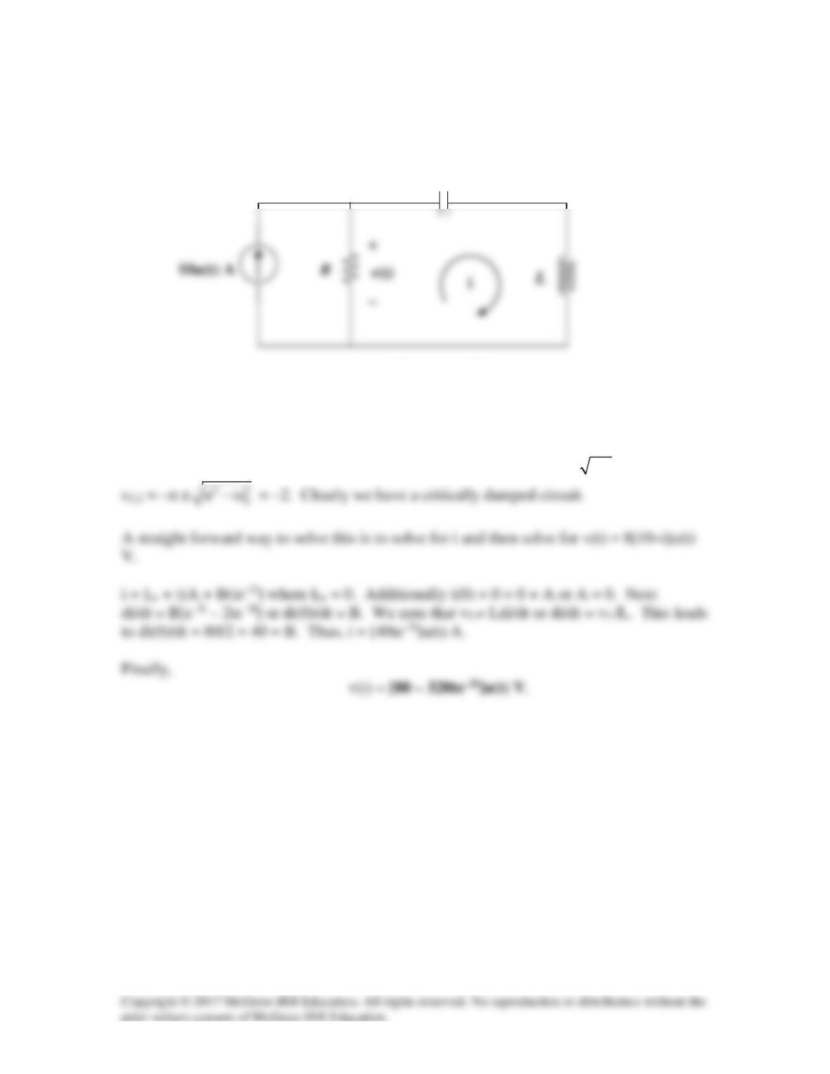
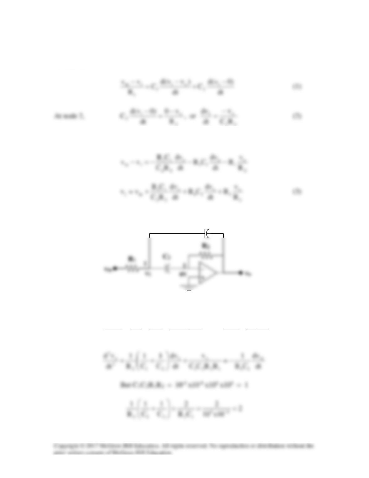
Solution 8.62
Find the response v(t) for t > 0 in the circuit in Fig. 8.107. Let R = 8 Ω, L = 2 H, and C =
125 mF.
Figure 8.107
For Prob. 8.62.
Solution
This is actually a series RLC circuit where α = R/(2L) = 2 and ω0 = 1/
LC
= 2 and
C
Solution 8.63
0 (0 )
s o so
v d v v d v
C C
R d t R d t
−−
= → = −
Solution 8.64
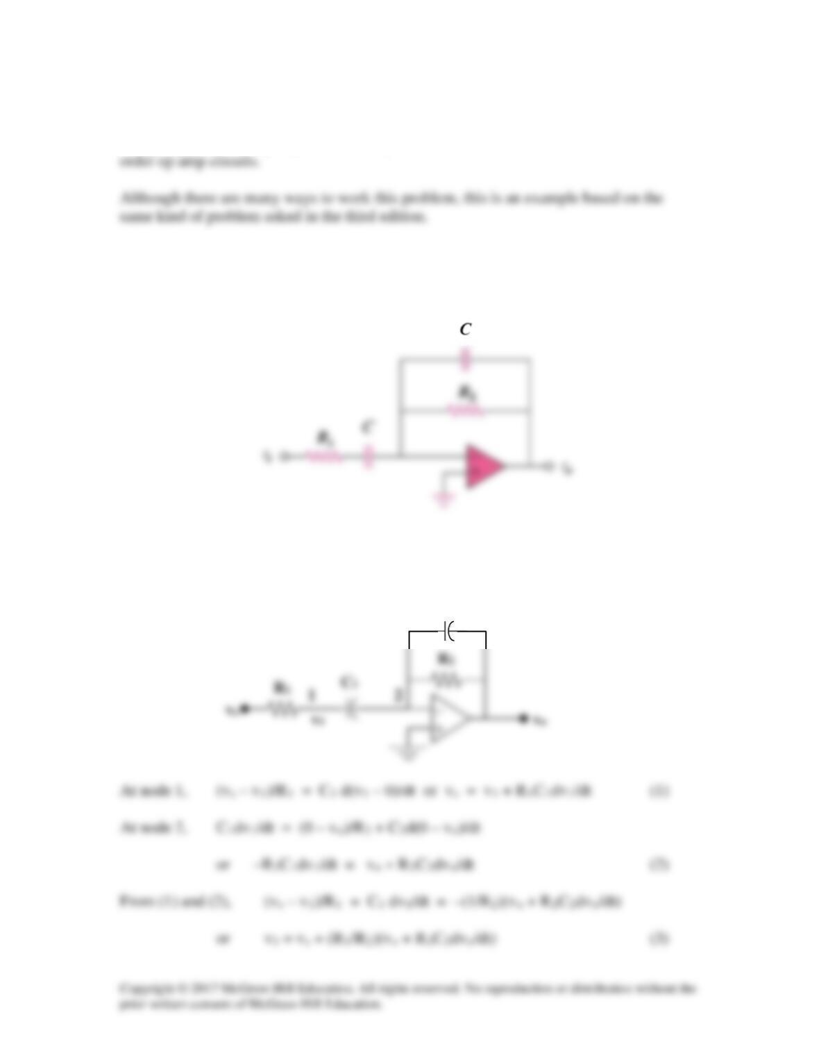
Using Fig. 8.109, design a problem to help other students to better understand second-
Problem
Obtain the differential equation for vo(t) in the network of Fig. 8.109.
Figure 8.109
Solution
C2
C1
Substituting (3) into (1) produces,
vs = vs + (R1/R2)(vo + R2C2dvo/dt) + R1C1d{vs + (R1/R2)(vo + R2C2dvo/dt)}/dt
Simplifying we get,
[d2vo/dt2] + {[(R1C2) + (R1R1C1/R2)]/((R1)2 C1C2)}dvo/dt + {(R1/R2)(vo)/
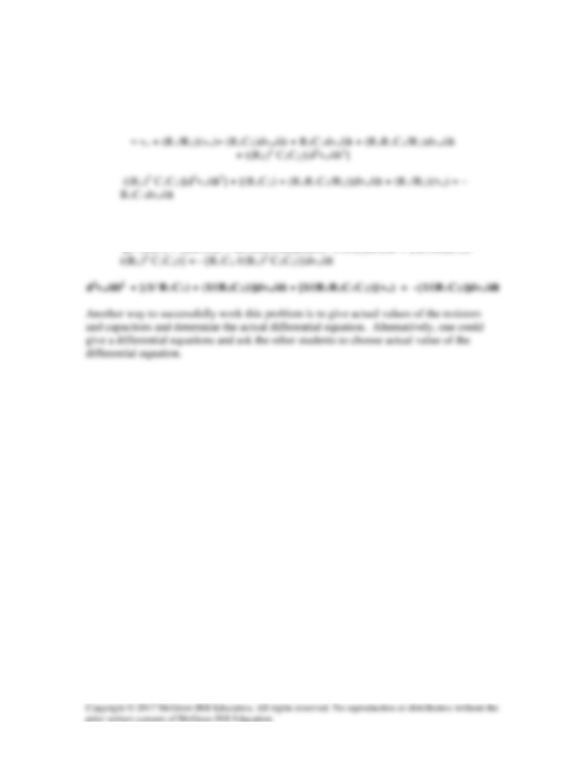
Solution 8.65
At the input of the first op amp,
Let us now examine our constraints. Since the input terminals are essentially at ground,
then we have the following,
Combining (1), (2), and (3), eliminating v1 and v2 we get,
And, we obtain,
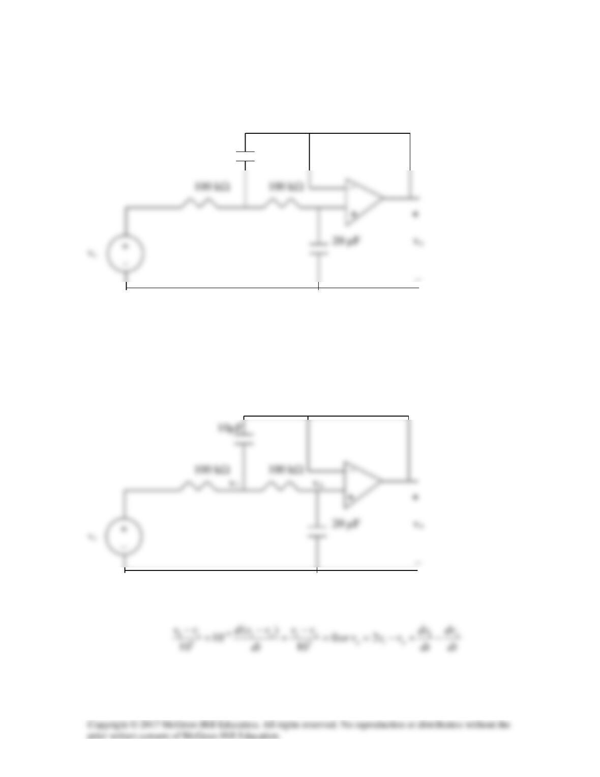
Solution 8.66
Obtain the differential equations for vo(t) in the op amp circuit in Fig. 8.111.
10µF
–
Figure 8.111
For Prob. 8.66.
Solution
We apply nodal analysis to the circuit as shown below.
vo
At node 1,
At node 2,
Solution 8.67
At node 1,
From (1) and (2),
C2
From (2) and (3),
dt
dv
R
R
dt
vd
CR
dt
dv
RC
CR
dt
dv
dt
dv
RC
v
o
2
1
2
o
2
11
o
22
11in1
22
o
+++==−
C1
As t approaches infinity, the capacitor acts like an open circuit so that
vin = 10u(t) mV and the fact that the initial voltages across each capacitor is 0
22
From (1) at t = 0+,
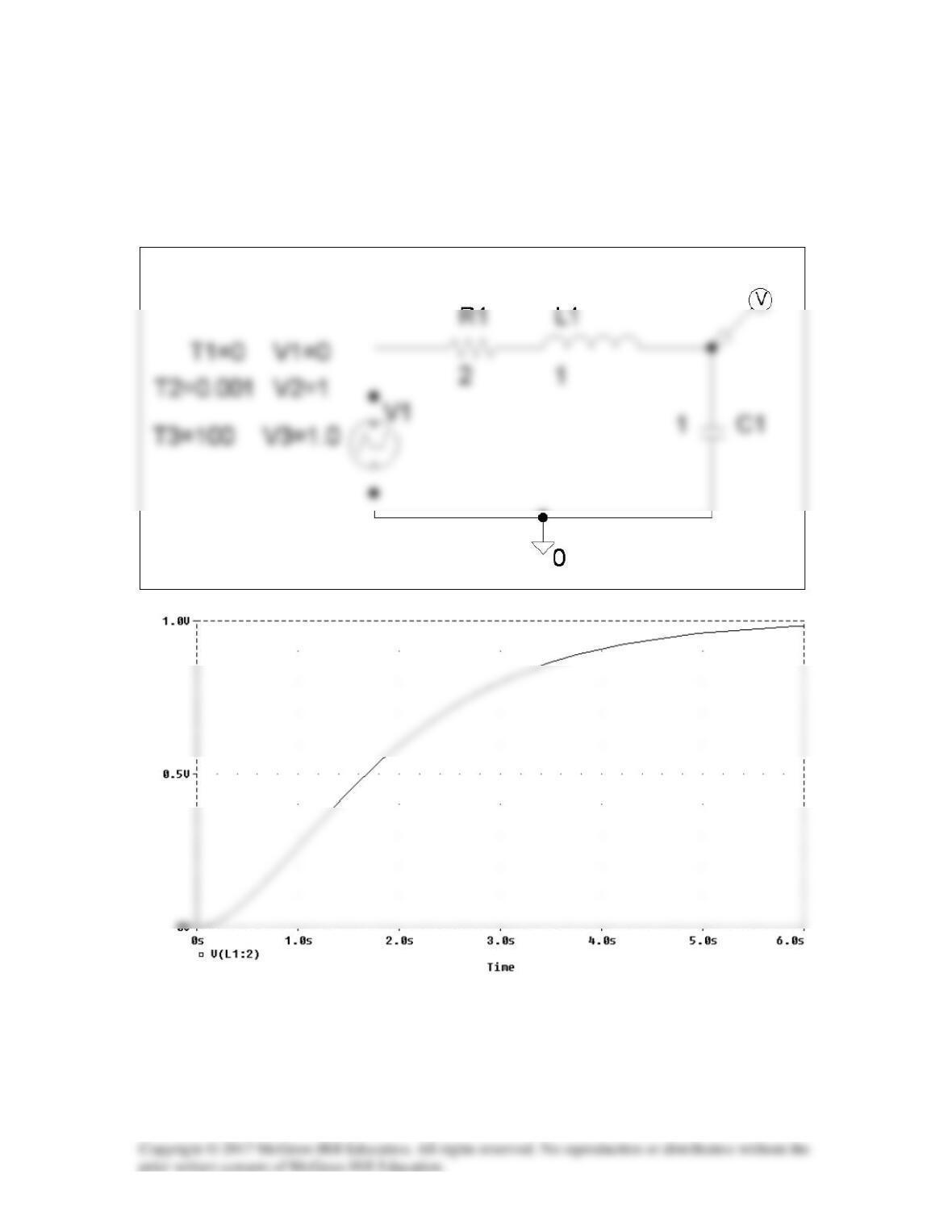
Solution 6.68
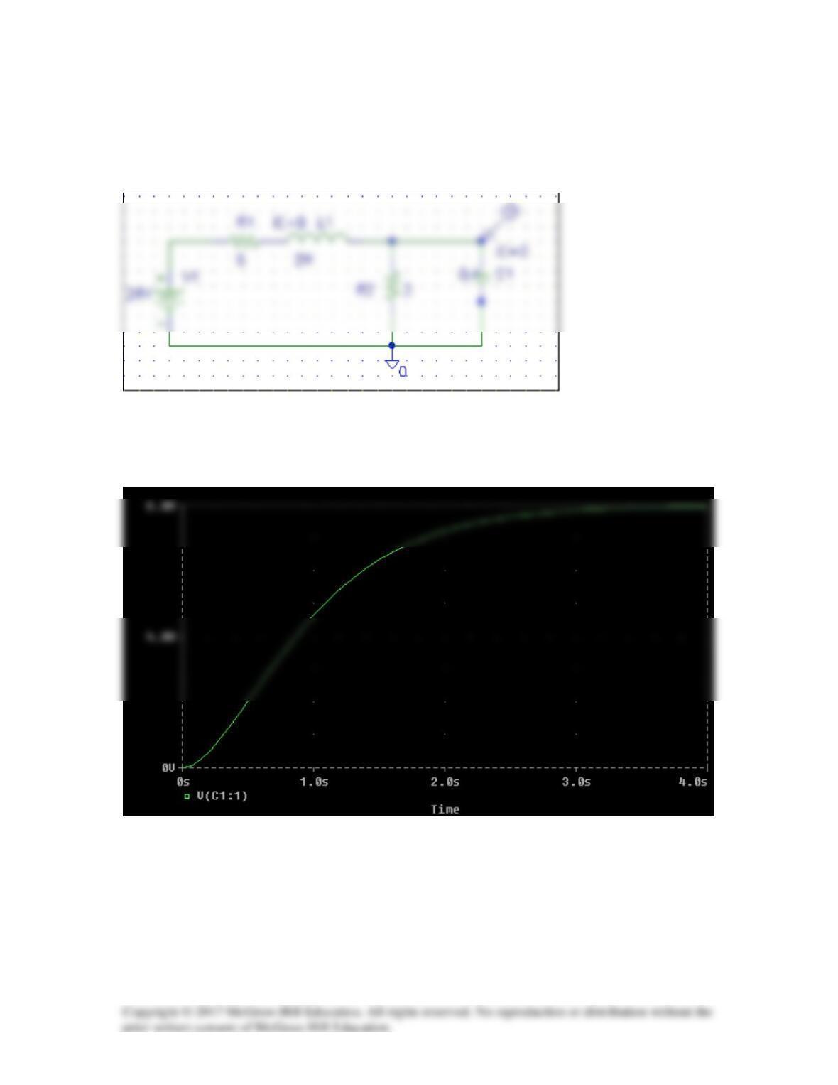
The schematic is as shown below. The unit step is modeled by VPWL as shown. We
insert a voltage marker to display V after simulation. We set Print Step = 25 ms and
final step = 6s in the transient box. The output plot is shown below.
Solution 8.69
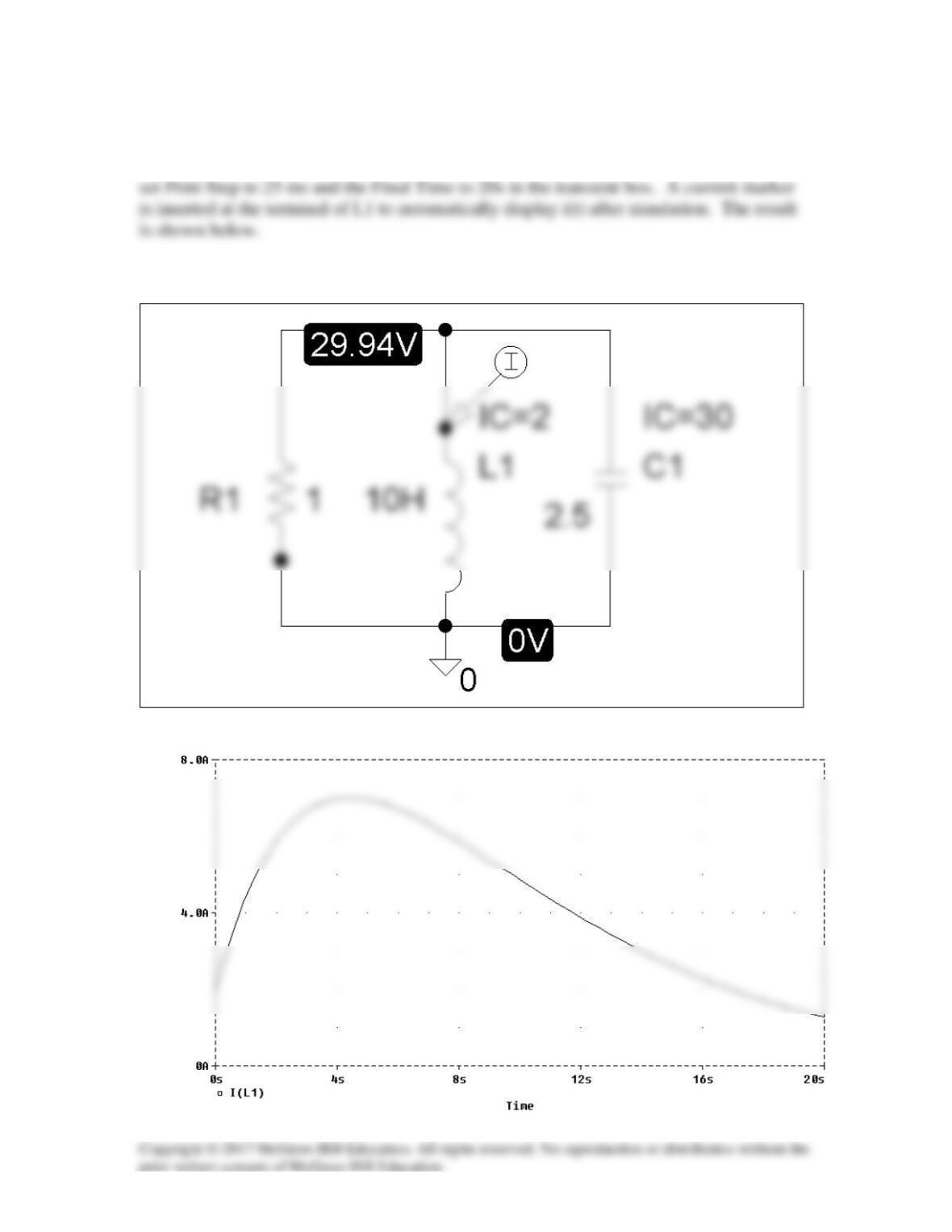
The schematic is shown below. The initial values are set as attributes of L1 and C1. We
Solution 8.70
The schematic is shown below.
After the circuit is saved and simulated, we obtain the capacitor voltage v(t) as shown
below.