Solution 13.44
We can apply the superposition theorem. Let i1 = i1’ + i1” and i2 = i2’ + i2” where
the single prime is due to the DC source and the double prime is due to the AC source.
Since we are looking for the steady–state values of i1 and i2,
i1’ = i2’ = 0.
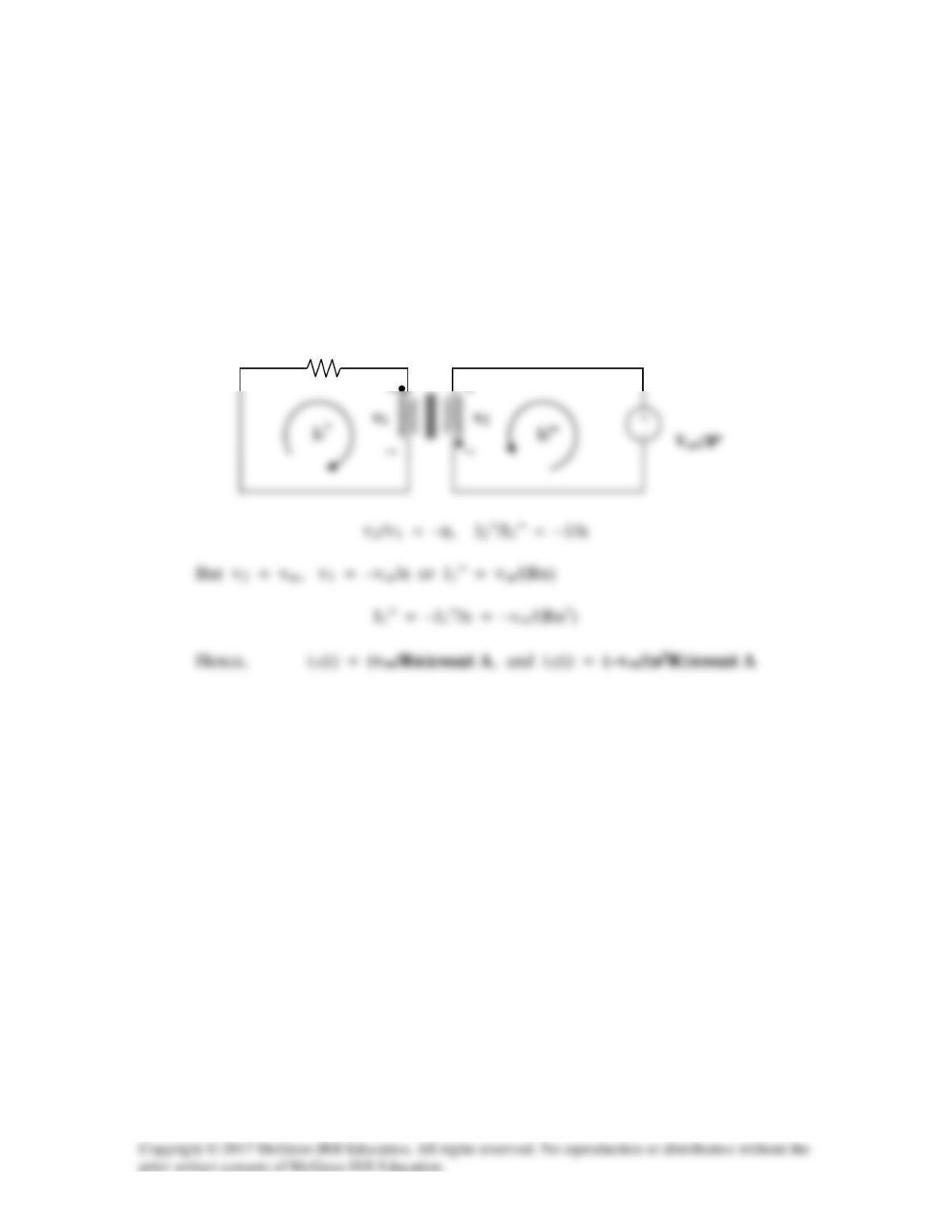
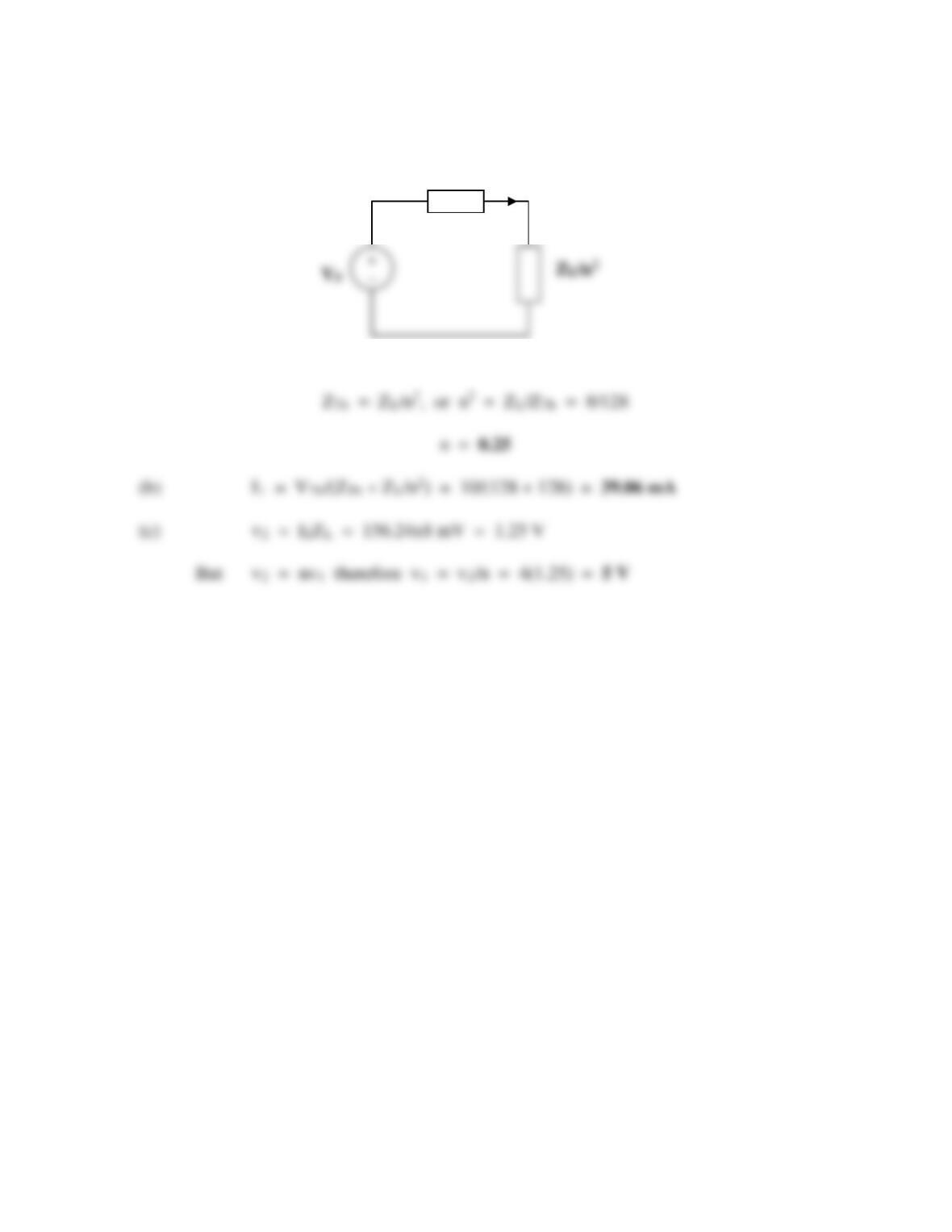
For the AC source, consider the circuit below.
R
1 : n
Solution 13.45
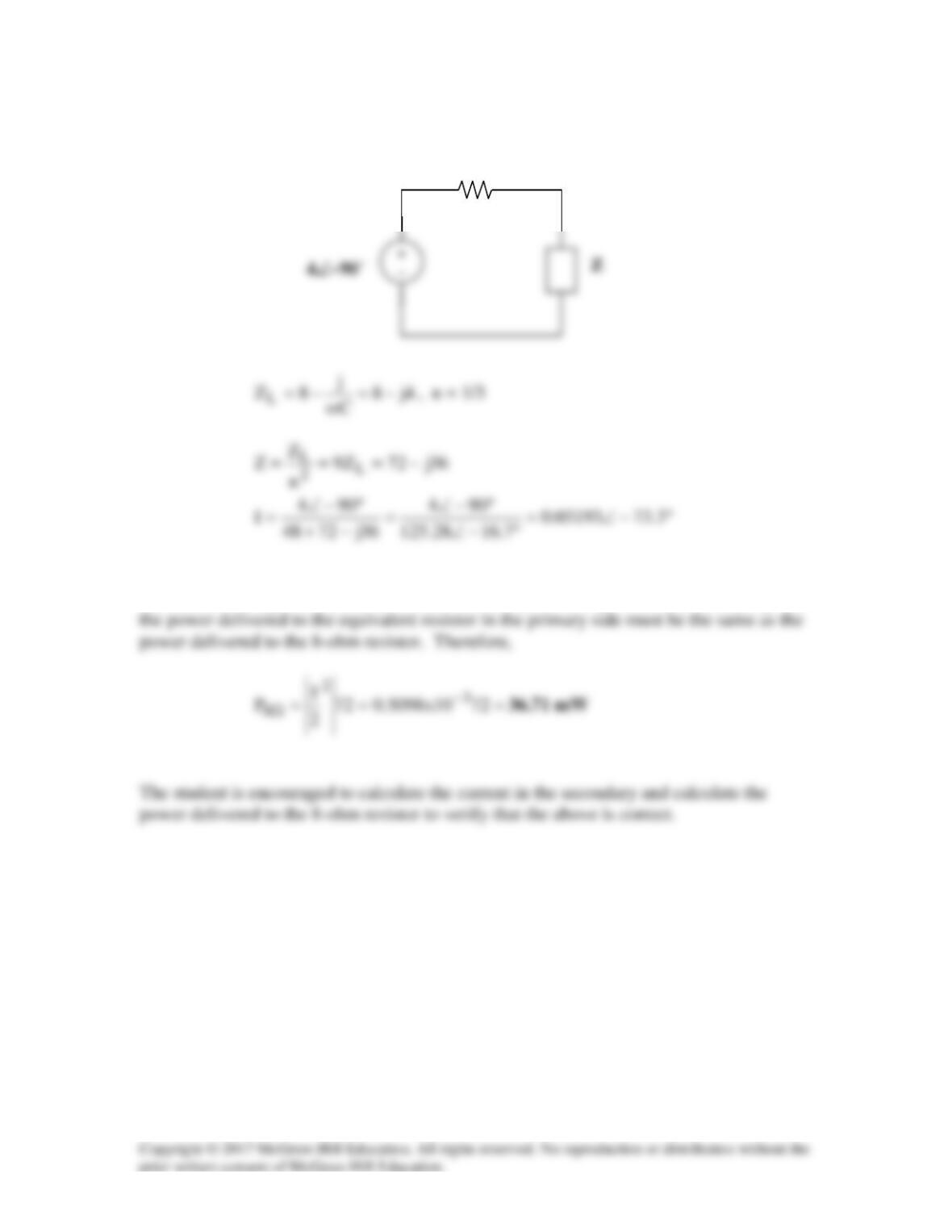
We now have some choices, we can go ahead and calculate the current in the second loop
and calculate the power delivered to the 8–ohm resistor directly or we can merely say that
48 Ω
Solution 13.46
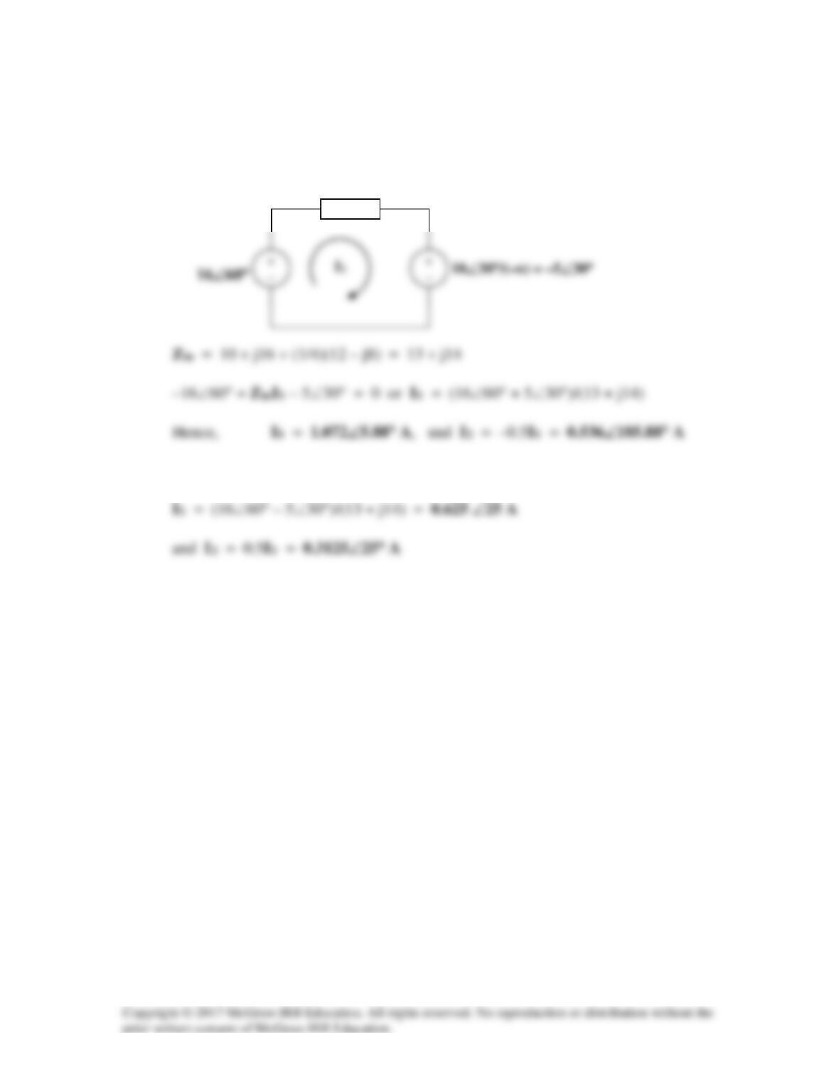
(a) Reflecting the secondary circuit to the primary, we have the circuit shown below.
(b) Switching a dot will not affect Zin but will affect I1 and I2.
Zin
Solution 13.47
Find v(t) for the circuit in Fig. 13.111.
Figure 13.111
For Prob. 13.47.
Solution
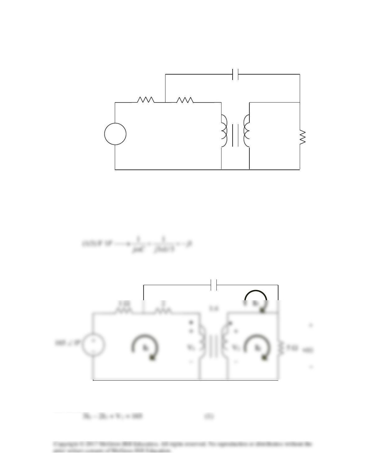
Consider the circuit shown below.
1 Ω
1:4
+
_
+
_
For mesh 1,
–j
1 Ω
+
_
165 sin(3t) V
•
•
5 Ω
1:4
2 Ω
+
_
v(t)
1/3 F
For mesh 2,
At the terminals of the transformer,
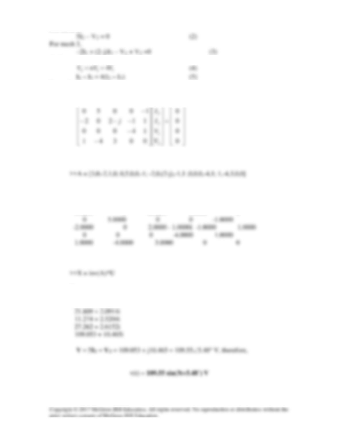
In matrix form,
−
165
01203
1
I
Solving this using MATLAB yields
A =
3.0000 0 -2.0000 1.0000 0
>>U = [165;0;0;0;0]
X =
53.427 + 0.8085i
Solution 13.48
Using Fig. 13.113, design a problem to help other students to better understand how ideal
transformers work.
Although there are many ways to solve this problem, this is an example based on the
same kind of problem asked in the third edition.
Problem
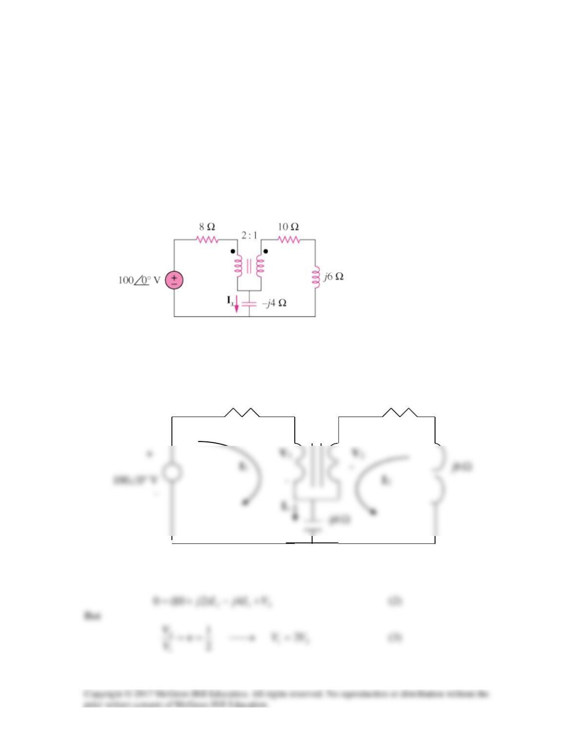
Find Ix in the ideal transformer circuit of Fig. 13.112.
Figure 13.112
Solution
We apply mesh analysis.
8
Ω
2:1 10
Ω
+ +
••
Ω
Ω
121 4)48(100 VIjIj +−−=
(1)
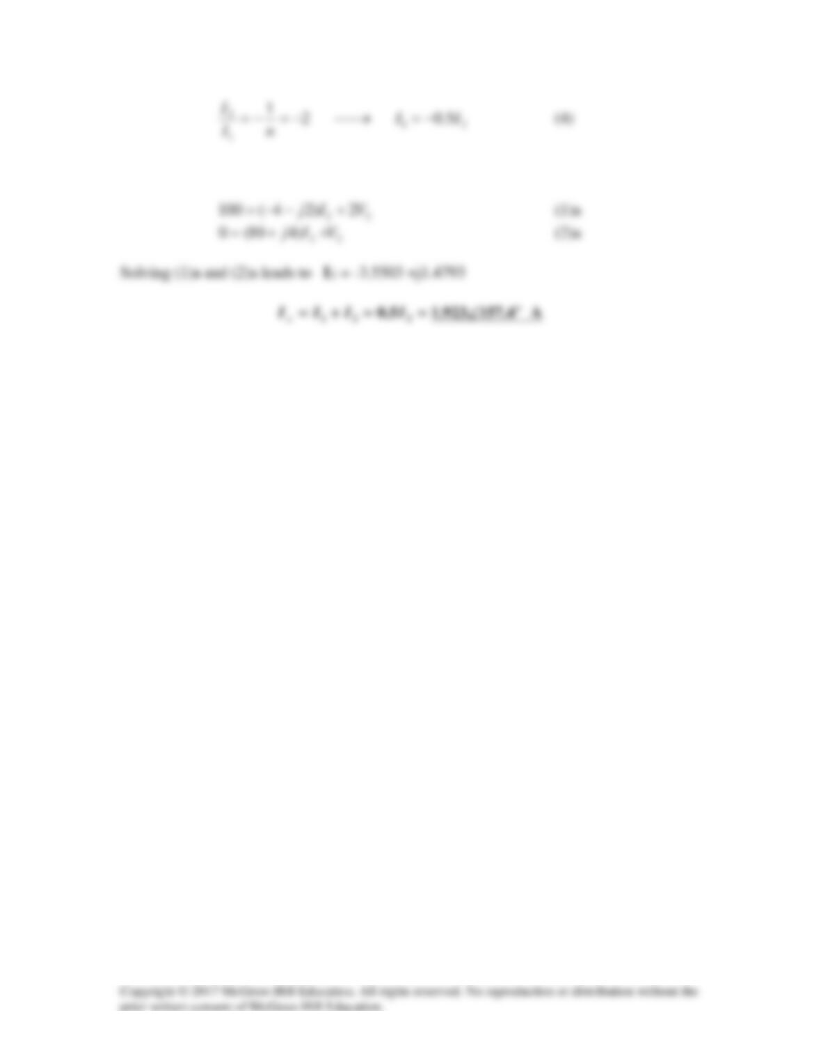
Substituting (3) and (4) into (1) and (2), we obtain
Solution 13.49
Ix -j10
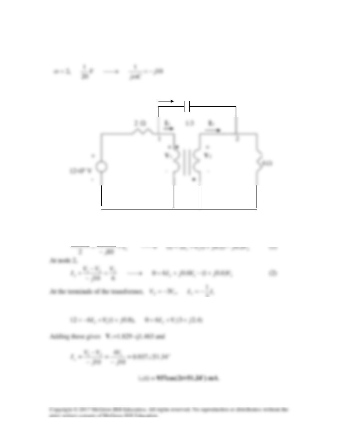
At node 1,
211
12 VjjVII
VVV −++=→+
−
−
3
Substituting these in (1) and (2),
Solution 13.50
The value of Zin is not effected by the location of the dots since n2 is involved.
Zin’ = (6 – j10)/(n’)2, n’ = 1/4
Solution 13.51
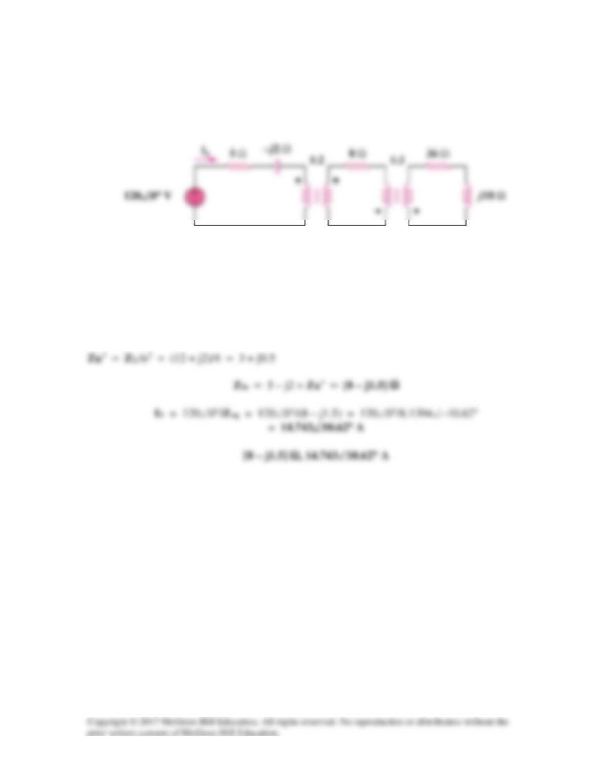
Use the concept of reflected impedance to find the input impedance and current I1 in
Fig. 13.115 below.
Figure 13.115
For Prob. 13.51.
Solution
Let Z3 = 36 +j18, where Z3 is reflected to the middle circuit.
Solution 13.52
For maximum power transfer,
Solution 13.53
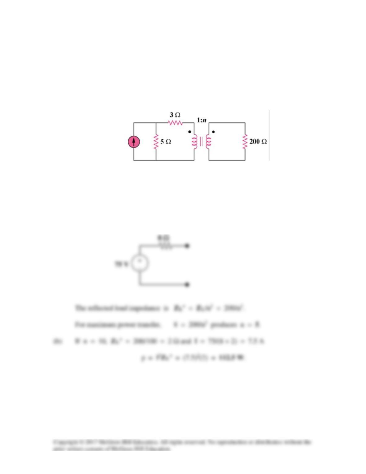
Refer to the network in Fig. 13.117.
(a) Find n for maximum power supplied to the 200-Ω load.
(b) Determine the power in the 200-Ω load if n = 10.
Figure 13.117
For Prob. 13.53.
Solution
(a) The Thevenin equivalent to the left of the transformer is shown below.
15∠0° A
Solution 13.54
(a)
For maximum power transfer,
I1
ZTh
Solution 13.55
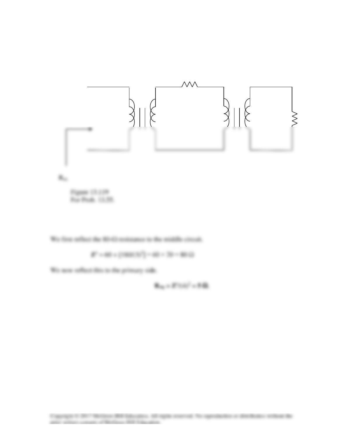
For the circuit in Fig. 13.119, calculate the equivalent resistance.
Solution
60 Ω
1:4
1:3
180 Ω
Solution 13.56
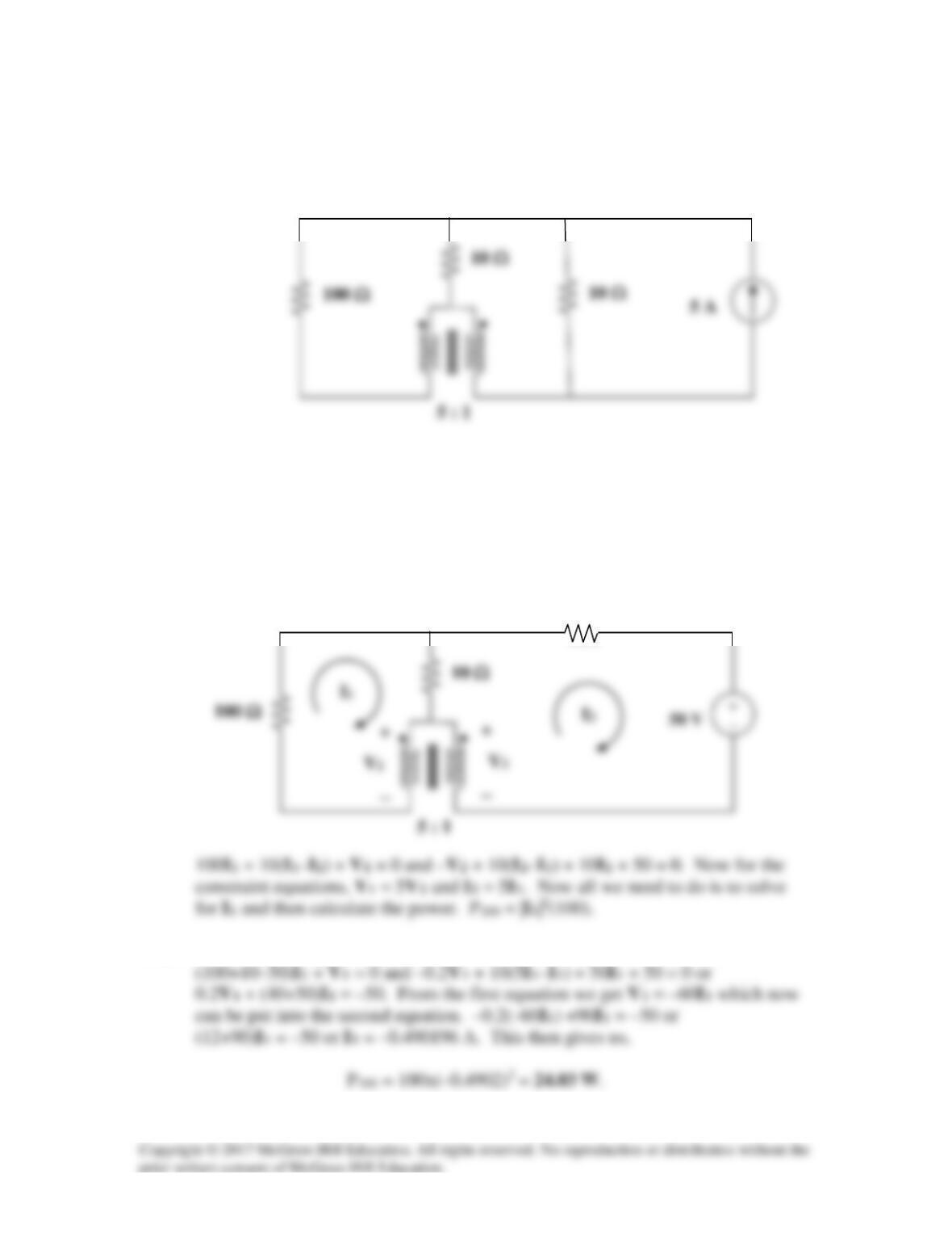
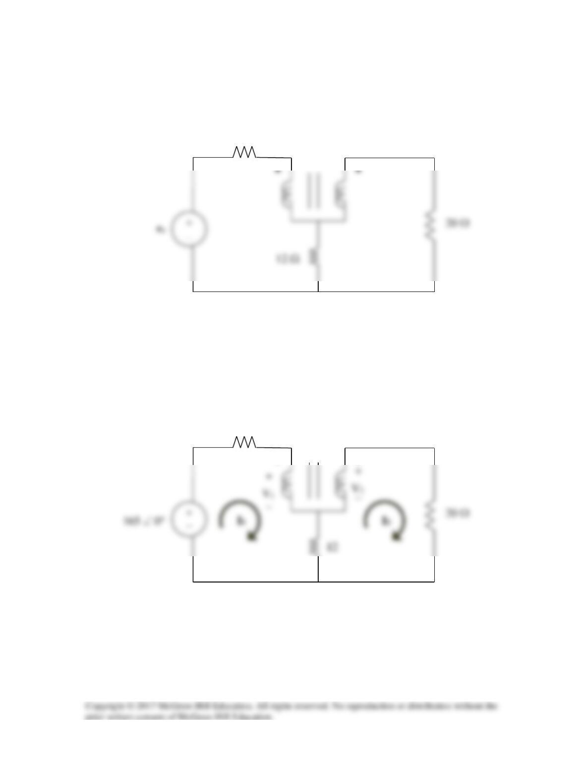
Find the power absorbed by the 100-Ω resistor in the ideal transformer circuit of
Fig. 13.120.
Figure 13.120
For Prob. 13.56.
Solution
Step 1. First we transform the current source in parallel with the 10 Ω into a
voltage source, equal to 5×10 = 50 V, in series with a 10 Ω resistor. Then we can
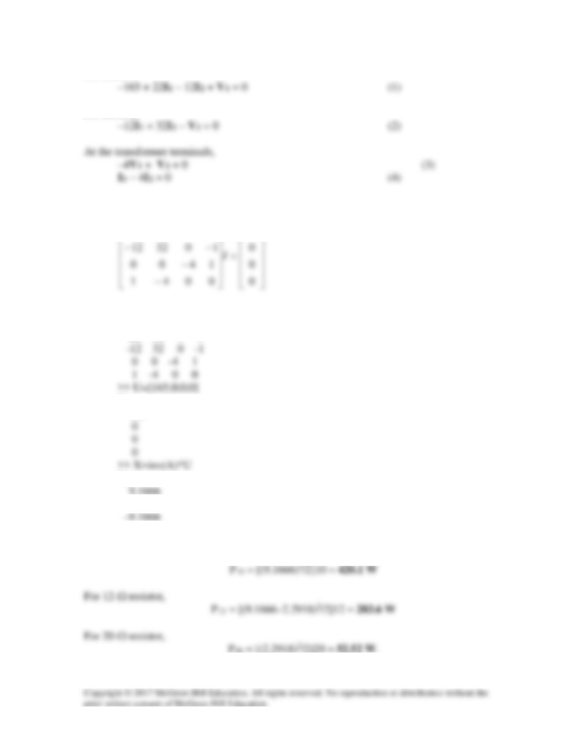
write the mesh equations.
Step 2. Replacing V2 and I2 in the above equations gives us,
10 Ω
Solution 13.57
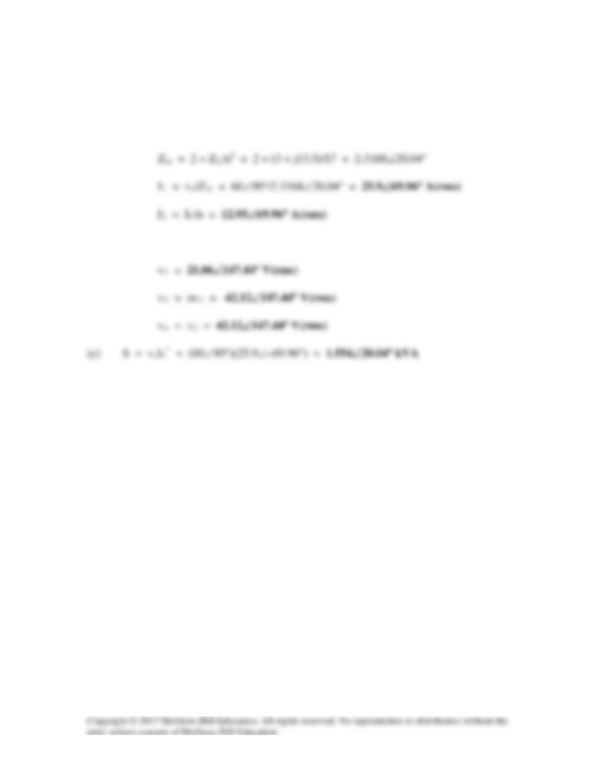
(a) ZL = j3||(12 – j6) = j3(12 – j6)/(12 – j3) = (12 + j54)/17
Reflecting this to the primary side gives
(b) 60∠90° = 2I1 + v1 or v1 = j60 –2I1 = j60 – 51.8∠69.96°
Solution 13.58
Consider the circuit below.
I1
I2
20 Ω
For mesh 3, 40I3 – 20I1 + V2 – V1 = 0 which leads to
At the transformer terminals, V2 = –nV1 = –5V1 or 5V1 + V2 (4)
Solving using MATLAB,
20 Ω
I3
A =
20 0 -20 1 0
B =
80
0
Y =
0.5161
-10.3226
Solution 13.59
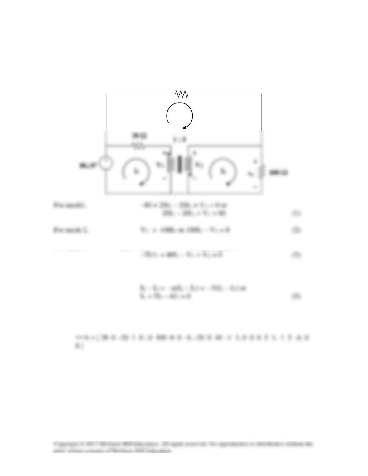
In the circuit in Fig. 13.123, let vs = 165sin(1,000t) V. Find the average power delivered
to each resistor.
Figure 13.123
For Prob. 13.59.
Solution
We apply mesh analysis to the circuit as shown below.
V
•
•
10 Ω
1:4
10 Ω
1:4
For mesh 1,
For mesh 2,
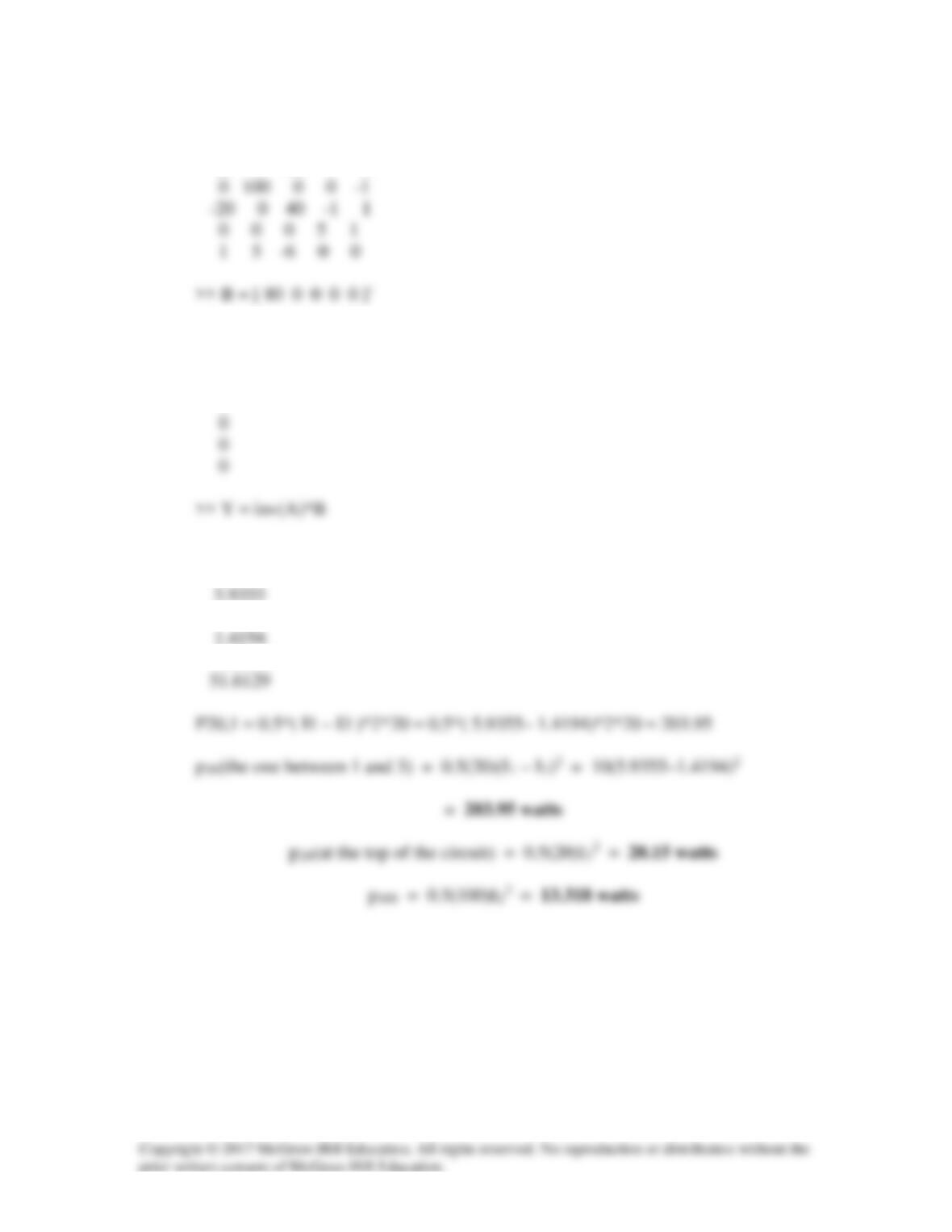
Putting (1), (2), (3), and (4) in matrix form, we obtain
−
165
011222
>> A=[22,-12,1,0;-12,32,0,-1;0,0,-4,1;1,-4,0,0]
A =
22 -12 1 0
U =
165
X =
2.2918
–36.6667
For 10-Ω resistor,