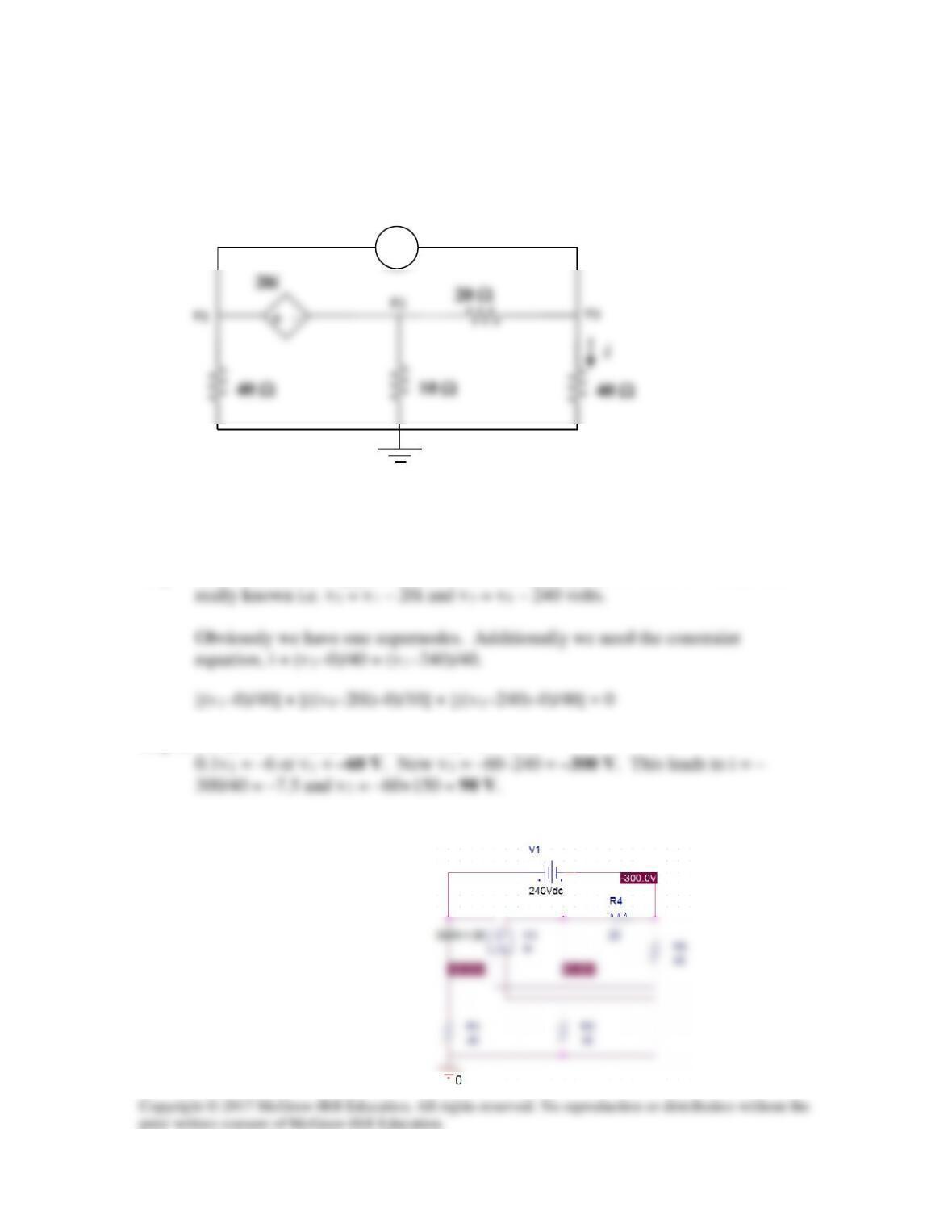
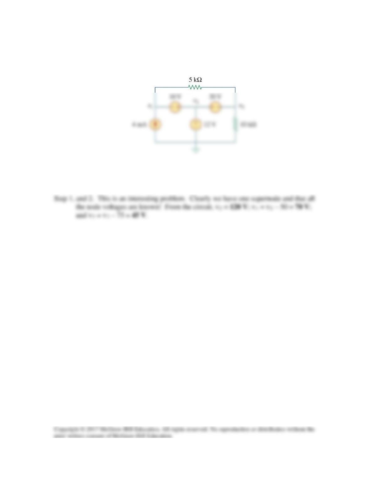
Solution 3.20
For the circuit in Fig. 3.69, find v1, v2, and v3 using nodal analysis.
Figure 3.69
For Prob. 3.20.
Step 1. This is an interesting problem, once we choose, say v1, the other two nodes are
Step 2. (0.025+0.1+0.025)v1 – 0.05v1 + 12 – 6 = 0 or
Checking with PSpice we get,
+ −
240 V
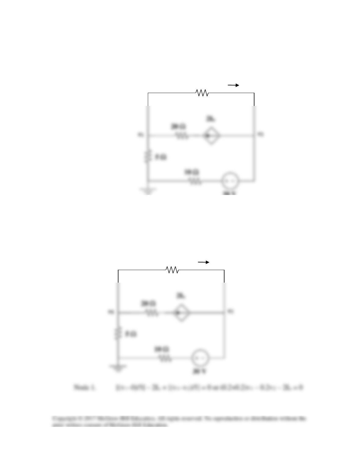
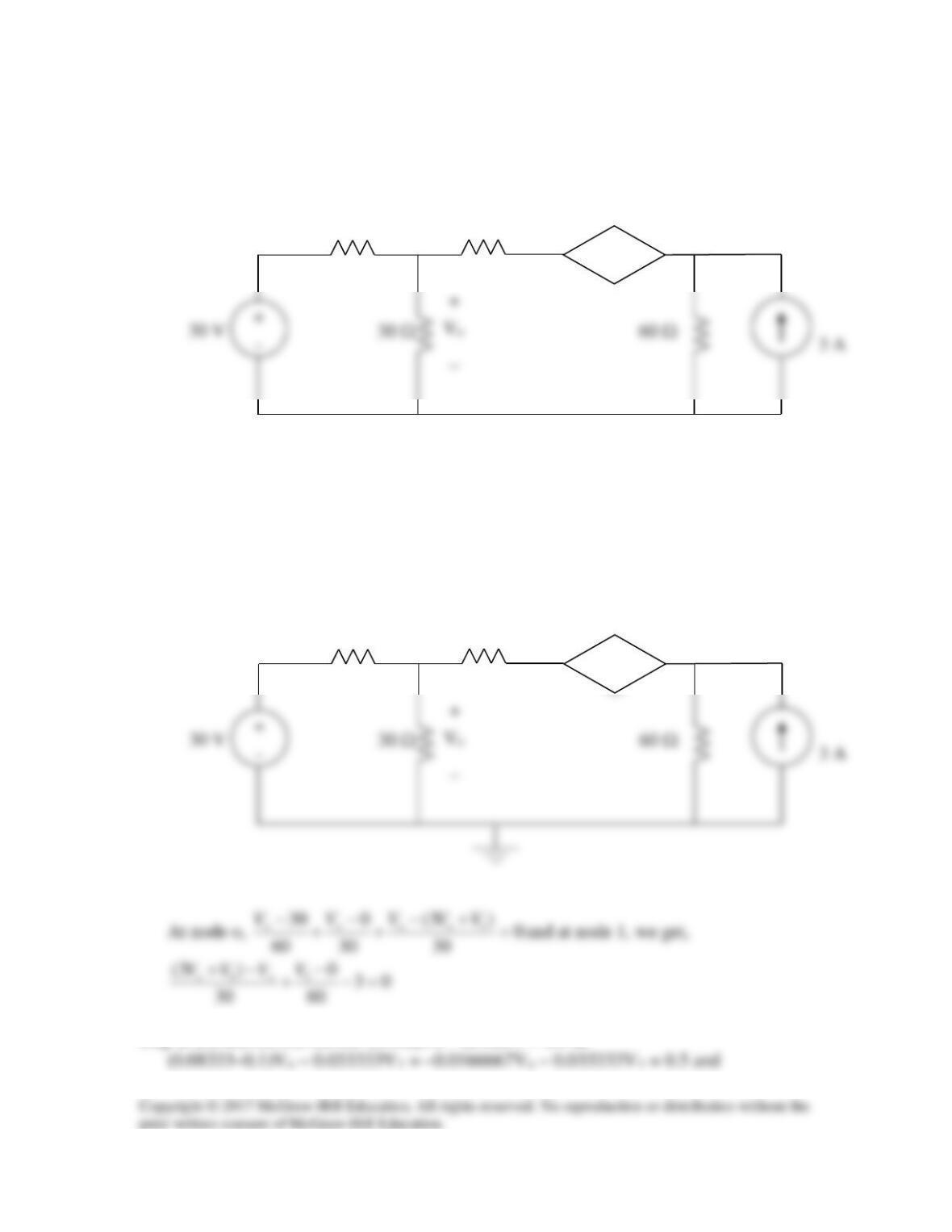
Solution 3.21
For the circuit in Fig. 3.70, find v1 and v2 using nodal analysis.
20 Ω
5 Ω
Figure 3.70
For Prob. 3.21.
Step 1. We start by writing the nodal equations. Then we need a constraint equation.
This then will allow us to solve for v1 and v2.
30 V
20 Ω
5 Ω
5 Ω
30 V
Io
5 Ω
Io
10 Ω
20 Ω
10 Ω
Solution 3.22
Determine v1 and v2 in the circuit in Fig. 3.71.
Solution
Step 1. We have two unknown so we end up with two nodal equations,
Step 2. (0.1+0.05+0.1)v1 – 0.1v2 = –2 = 0.25v1 – 0.1v2 and
Checking with PSpice we get,
Solution 3.23
Use nodal analysis to find Vo in the circuit of Fig. 3.72.
30 Ω
60 Ω
+
_
V
Figure 3.72
For Prob. 3.23.
Solution
Step 1. We apply nodal analysis to the circuit shown below.
30 Ω
60 Ω
_
Step 2. [(1/60)+(1/30)+(1/30)–(3/30)]Vo – (1/30)v1 = 0.5 or
60 Ω
+
–
3V
o
30 Ω
V
o
V
1
60 Ω
+
–
3V
o
30 Ω
Checking with PSpice we get,
Solution 3.24
Consider the circuit below.
1 Ω
1 Ω
4 A
2 Ω
4V125.0V125.10
8
VV
4
1
0V
41
411
=−→=
−
+−
−
(1)
−
4
125.000125.1
+
_
V
o
8 Ω
2 A
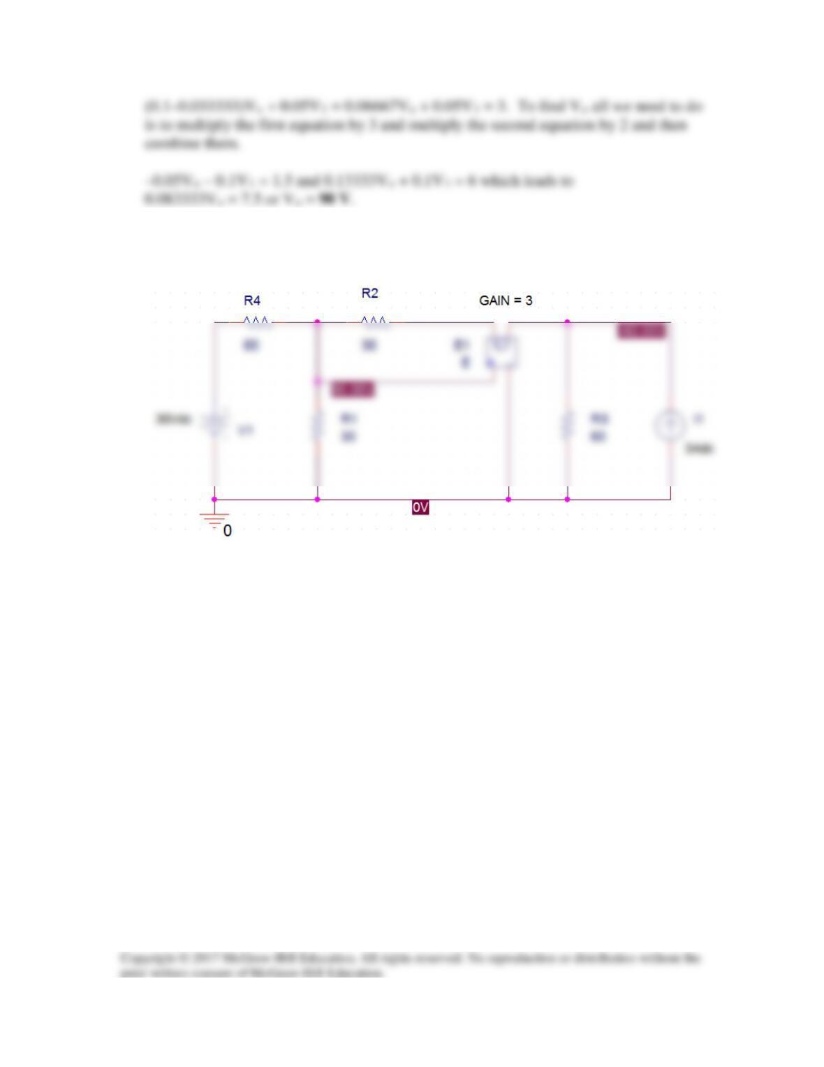
Now we can use MATLAB to solve for the unknown node voltages.
Y =
1.1250 0 0 -0.1250
>> I=[4,-4,-2,2]‘
I =
>> V=inv(Y)*I
V =
Solution 3.25
Consider the circuit shown below.
10
20
At node 1.
12 14
VV VV V VV
−−
At node 3,
23 3 34
VV V VV VVV
−−
Putting (1) to (4) in matrix form gives:
−−
1
80 21 20 0 1
V
10
4
20
Using MATLAB leads to
Solution 3.26
At node 1,
At node 2,
4
322
21
VVVI
VV
o
−
−
−
At node 3,
Putting (1), (3), and (4) in matrix form produces
45
V
247
−
−−
Solution 3.27
At node 1,
At node 2,
At node 3,
In matrix form,
−
2
v
4117
1
4117
−
4112
−
Solution 3.28
At node c,
cbccd
VVVVV 21150
−
−
At node d,
cddda
VV
V
V60V −+=→
−
−−
We use MATLAB to invert A and obtain
−
56.10
Solution 3.29
At node 1,
42121141
45025 VVVVVVVV −−=−→=−++−+
(1)
At node 2,
At node 3,
At node 4,
Using MATLAB,
−
7708.0
Solution 3.30
80 Ω
80 V
At node 1,
[(v1–80)/10]+[(v1–4vo)/20]+[(v1–(vo–96))/40] = 0 or
At node 2,
–2io + [((vo–96)–v1)/40] + [(vo–0)/80] = 0 and io = [(v1–(vo–96))/40]
Using (1) and (2) we get,
−
6.5
225.0175.0
v
40 Ω
i0
– +
96 V
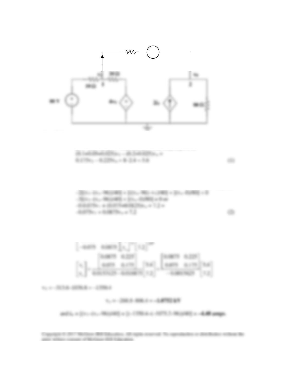
Solution 3.31
1 Ω
At the supernode,
But vo = v1 – v3. Hence (1) becomes,
At node 3,
At the supernode, v2 = v1 + 4io. But io =
4
v
3
. Hence,
1 Ω
+ v
0
–
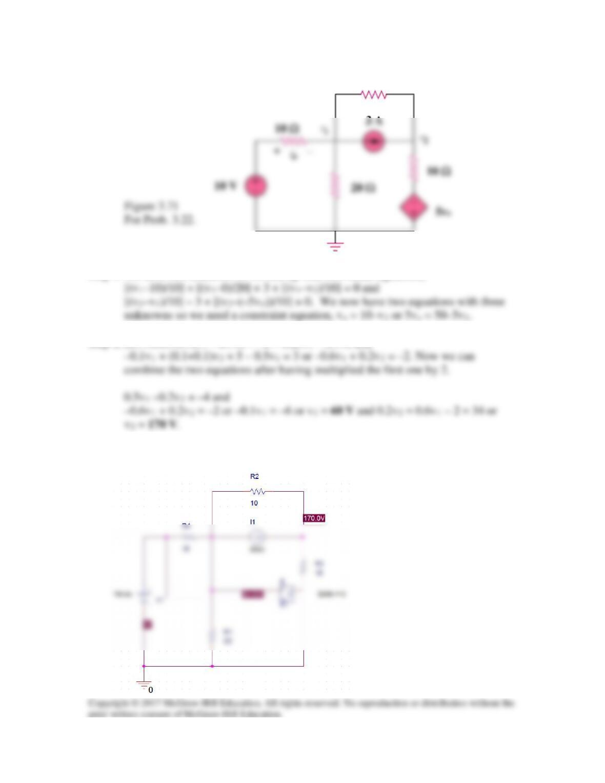
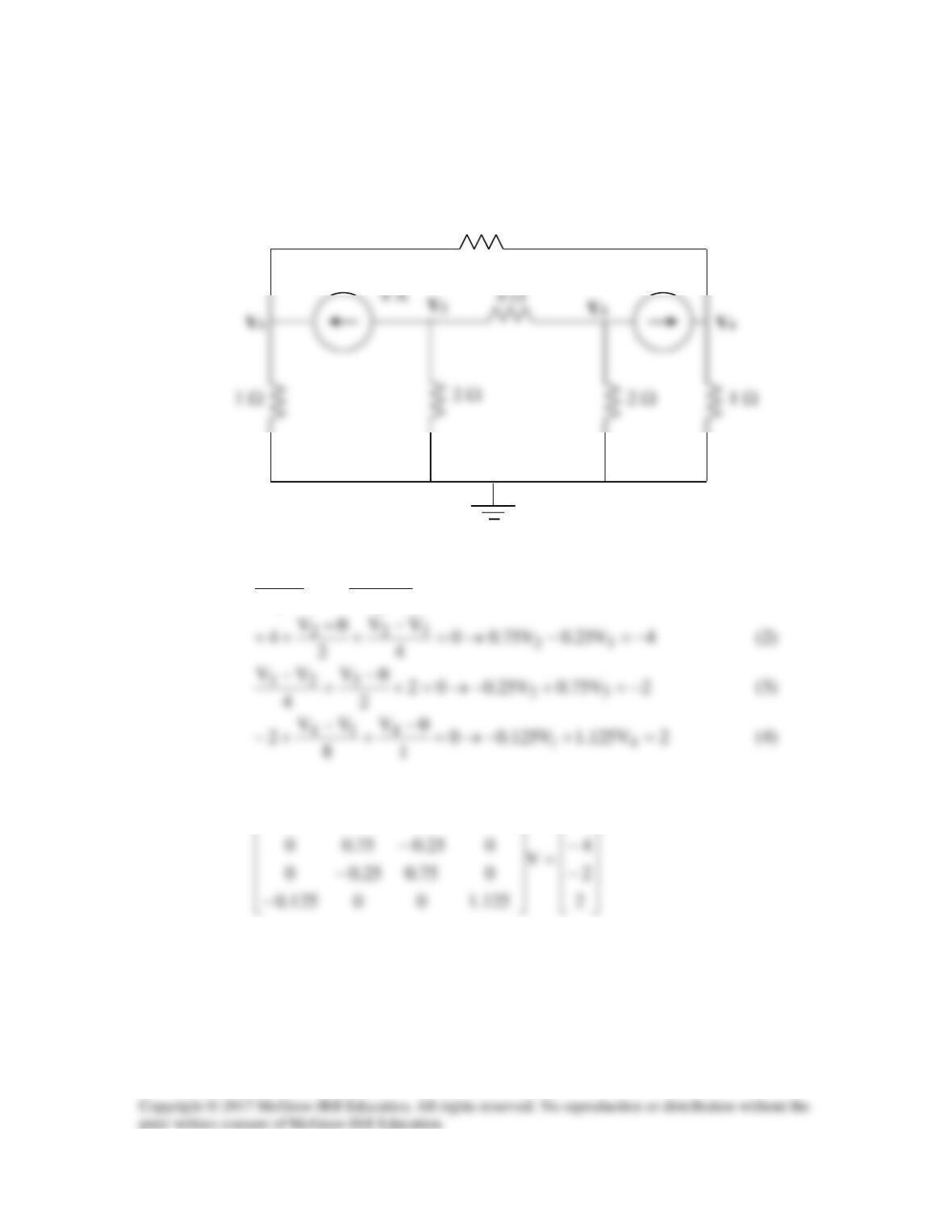
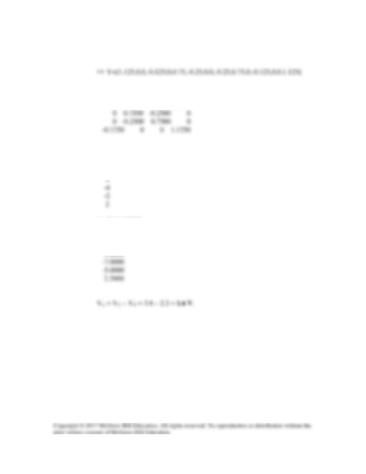
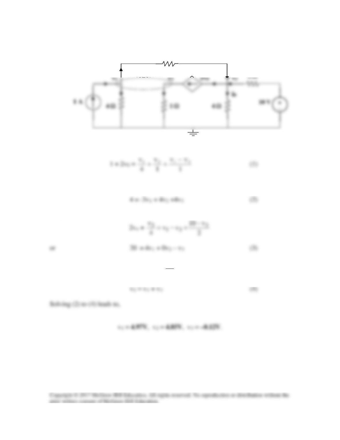
Solution 3.32
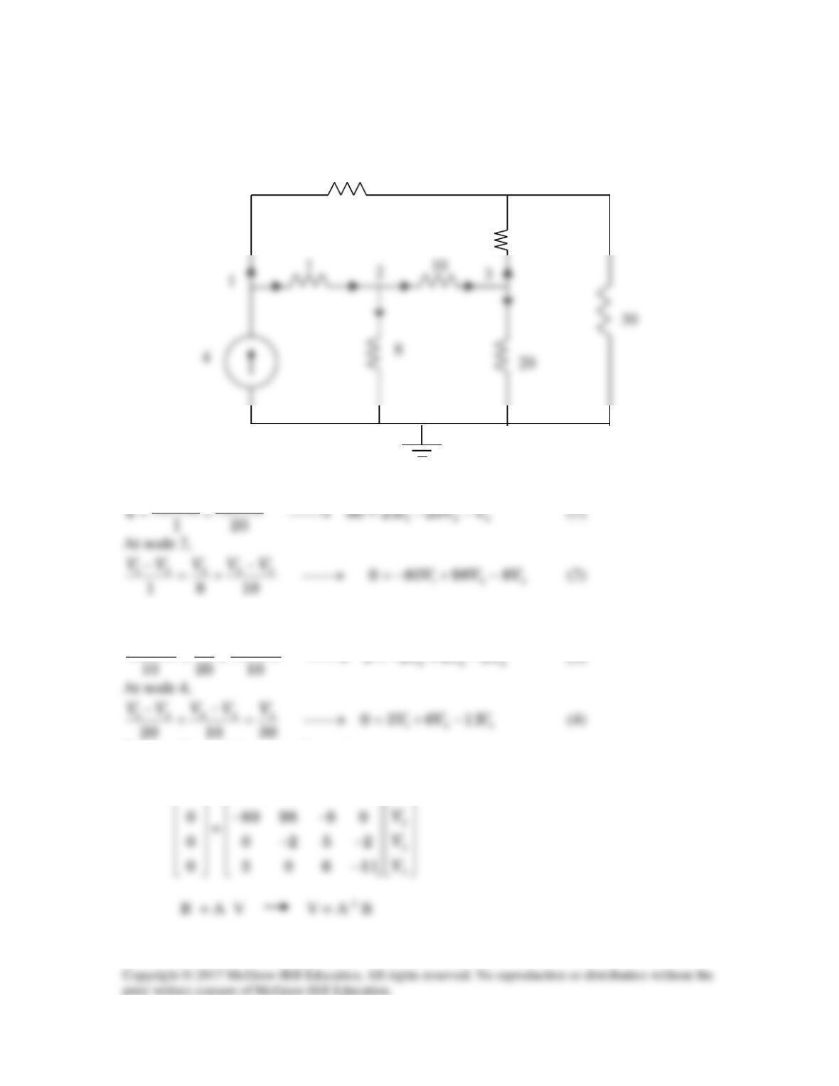
Obtain the node voltages v1, v2, and v3 in the circuit of Fig. 3.81.
Figure 3.81
For Prob. 3.32.
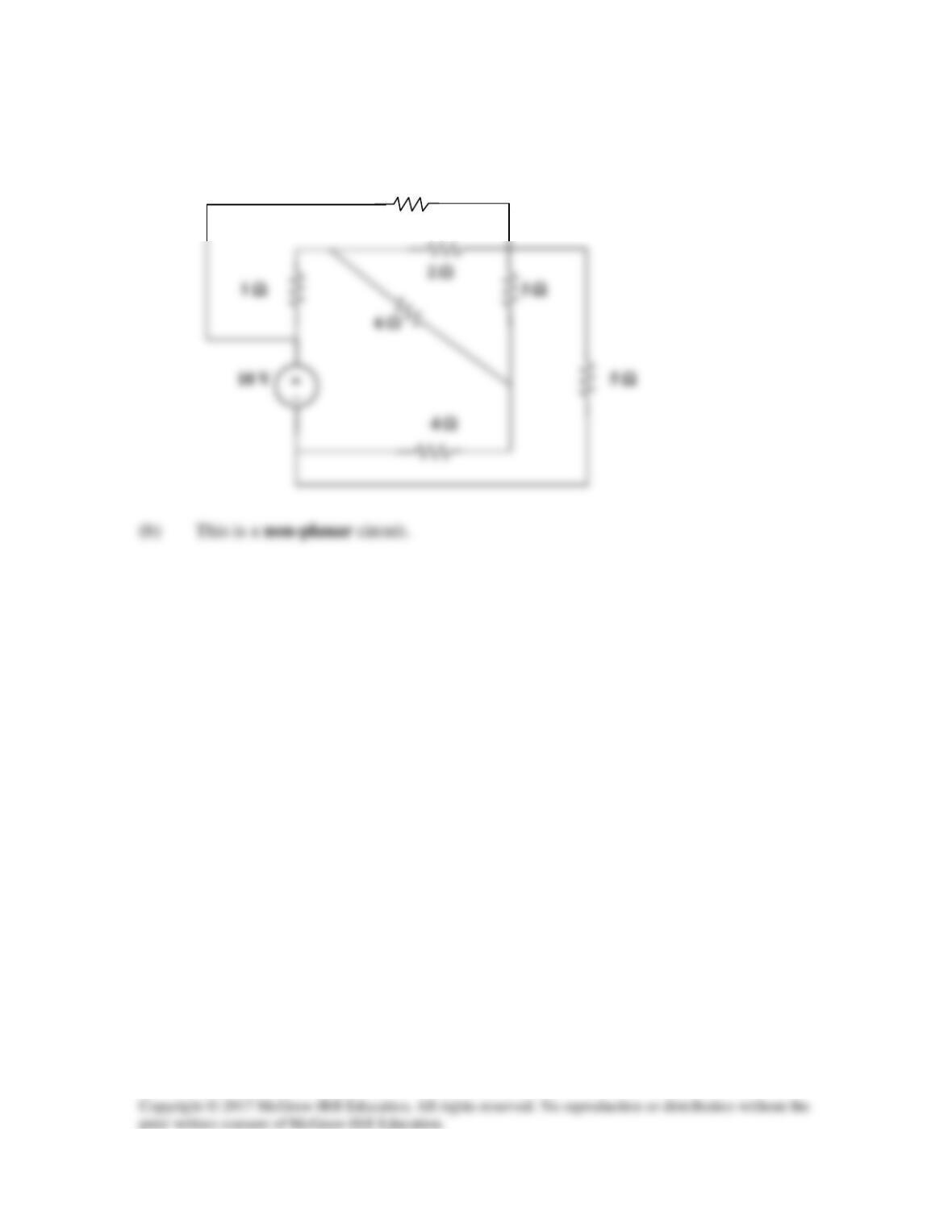
Solution 3.33
(a) This is a planar circuit. It can be redrawn as shown below.
4 Ω
3 Ω
6 Ω
1 Ω
2 Ω
(b) This is a planar circuit. It can be redrawn as shown below.
5 Ω
4 Ω
3 Ω
2 Ω
1 Ω
5 Ω
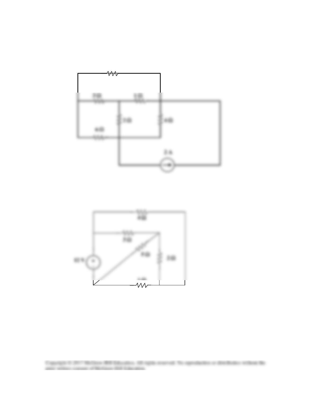
Solution 3.34
(a) This is a planar circuit because it can be redrawn as shown below,
6 Ω
5 Ω
4 Ω
3 Ω
1 Ω
7 Ω
Solution 3.35
For mesh 2,
+
30 V
+
20 V