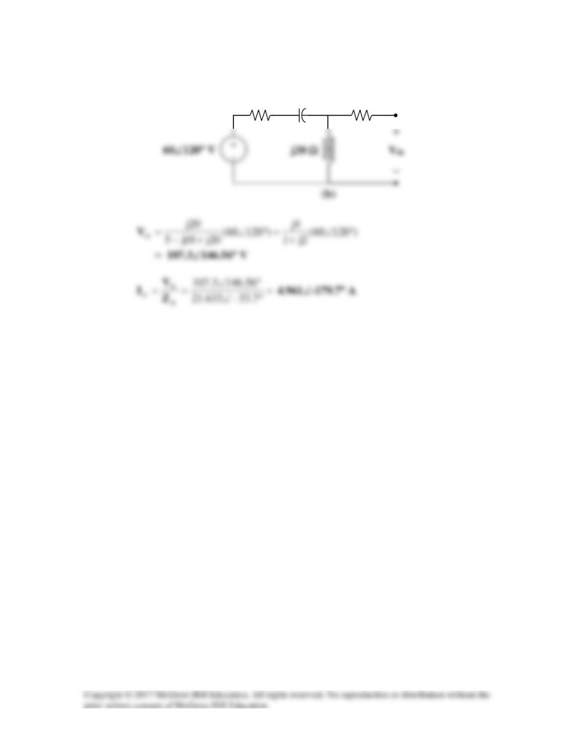
To find
th
V
, consider the circuit in Fig. (b).
2 Ω
-j10 Ω
5 Ω
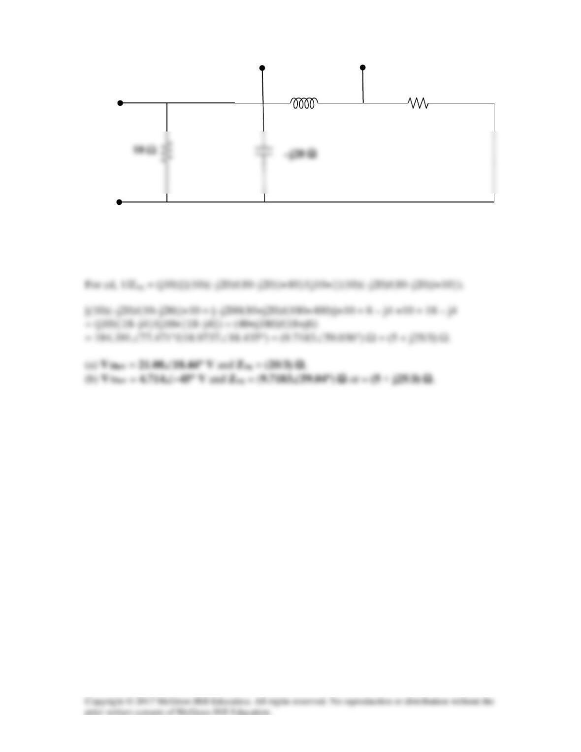
Solution 10.58
For the circuit depicted in Fig. 10.101, find the Thevenin equivalent circuit at terminals
a–b.
Figure 10.101
For Prob. 10.58.
Solution
The easiest way to do this is to find Voc and Isc. Writing a nodal equation at Vab will
10 Ω
a
b
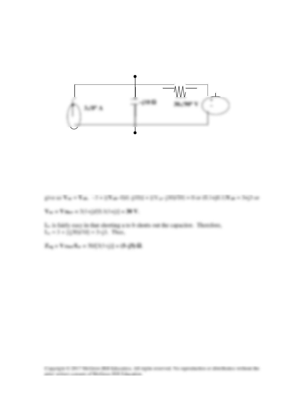
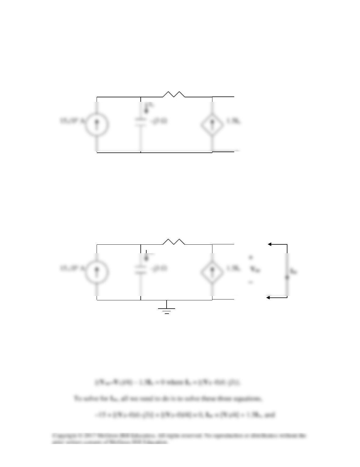
Solution 10.59
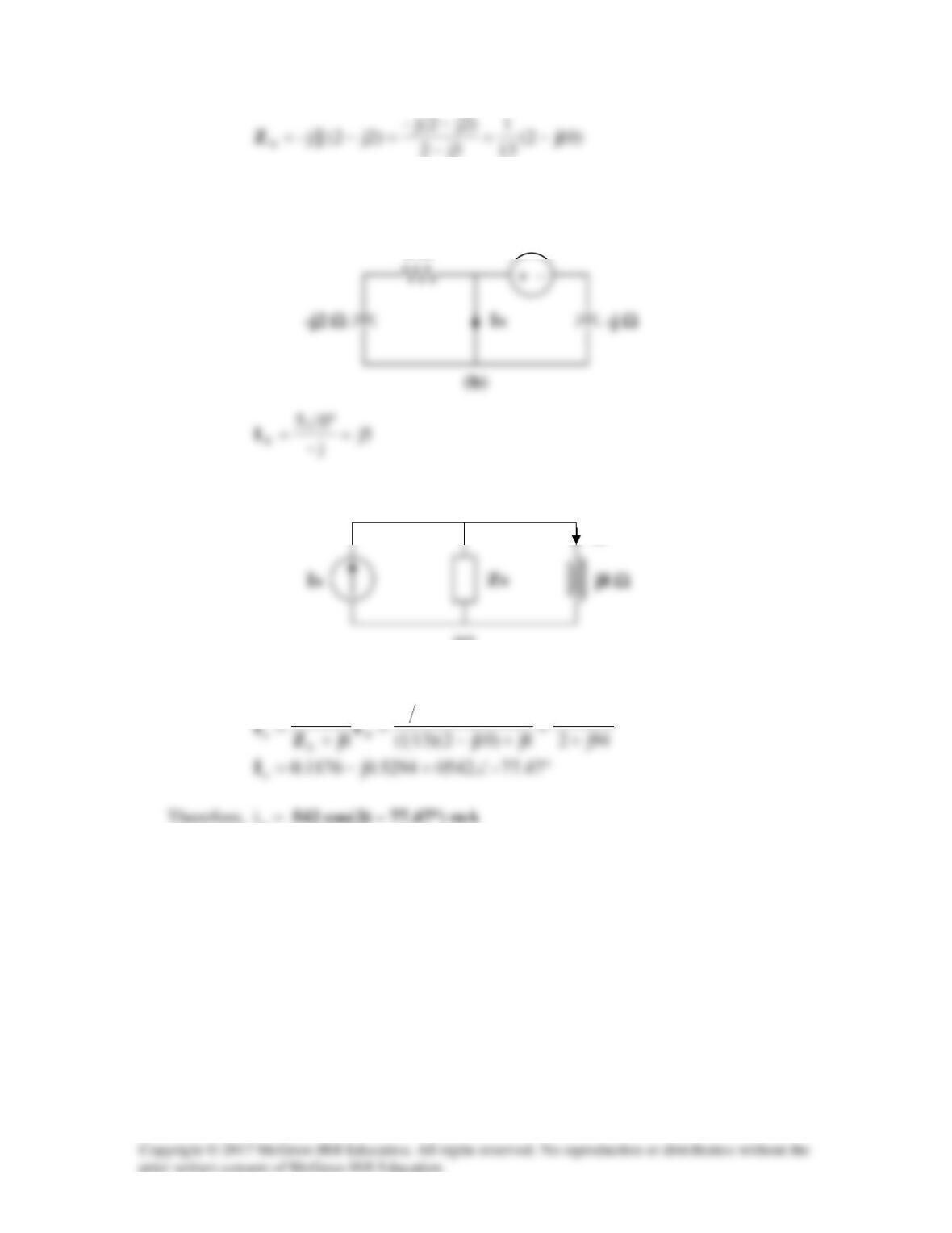
Calculate the output impedance of the circuit shown in Fig. 10.102.
Figure 10.102
For Prob. 10.59.
Solution
Since there are no independent sources, we need to inject a current, best value is to make
it 1 amp, into the terminals on the right and then to determine the voltage at the terminals.
Solution 10.60
Find the Thevenin equivalent of the circuit in Fig. 10.103 as seen from:
(a) terminals a–b
(b) terminals c–d
a
Figure 10.103
For Prob. 10.60.
Solution
Let us find the Thevenin equivalent circuits by finding Vab and Vcd in the above circuit
which gives us the Thevenin voltages. Next we set the independent sources to zero and
b
c
d
For ab, 1/Zeq = 0.1 +j0.05 + 0.05 – j0.05 = 0.15 or Zeq = (20/3) Ω.
j10 Ω
10 Ω
a
b
c
d
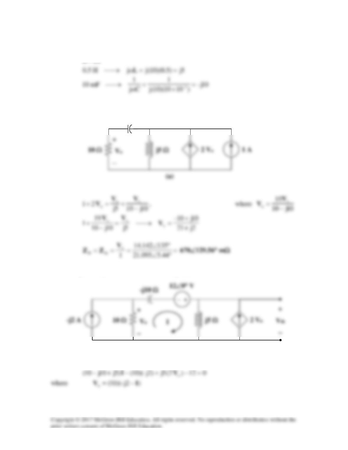
V1 and V2
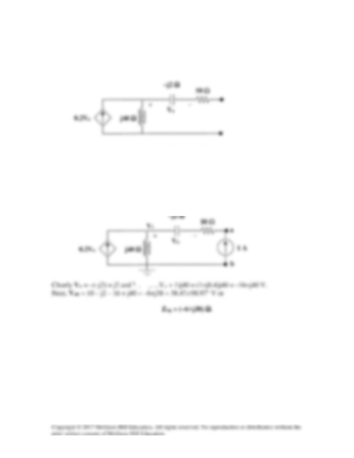
Solution 10.61
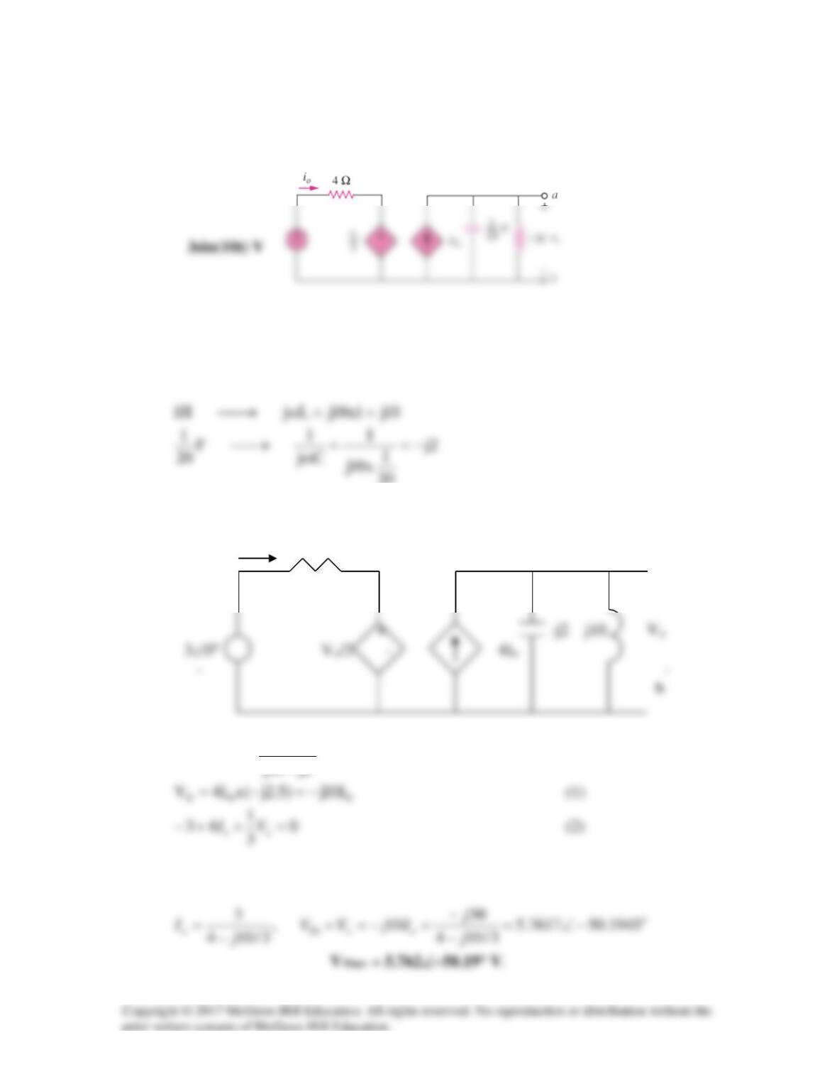
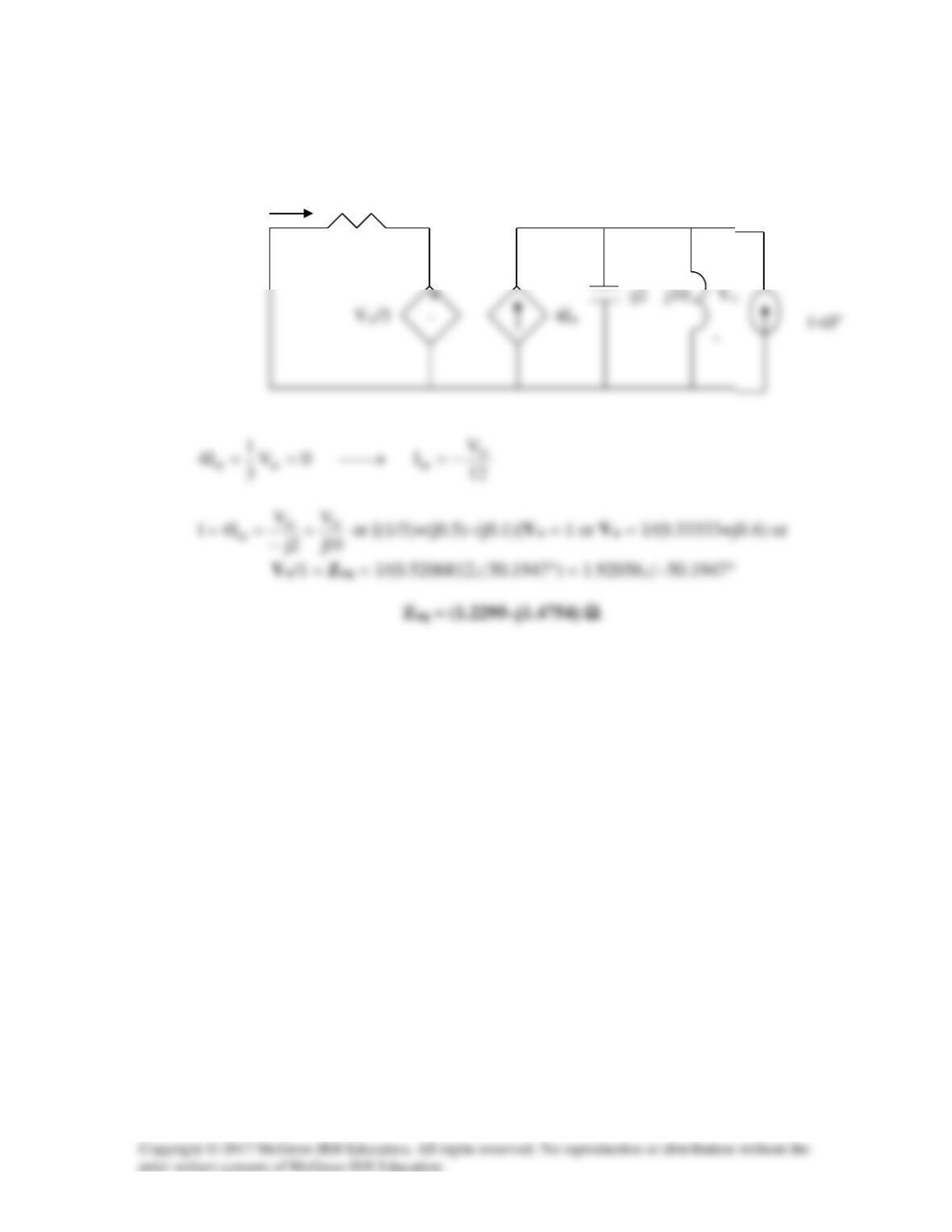
Find the Thevenin equivalent at terminals a-b of the circuit in Fig. 10.104.
4 Ω
a
b
Figure 10.104
For Prob. 10.61.
Solution
Find the Thevenin equivalent at terminals a-b of the circuit in Fig. 10.104.
4 Ω
a
b
Step 1. First we solve for the open circuit voltage using the above circuit and
writing two node equations. Then we solve for the short circuit current which
only needs one node equation. For being able to solve for Voc, we need to solve
these three equations,
–15 + [(V1–0)/(–j3)] + [(V1–Voc)/4] = 0 and
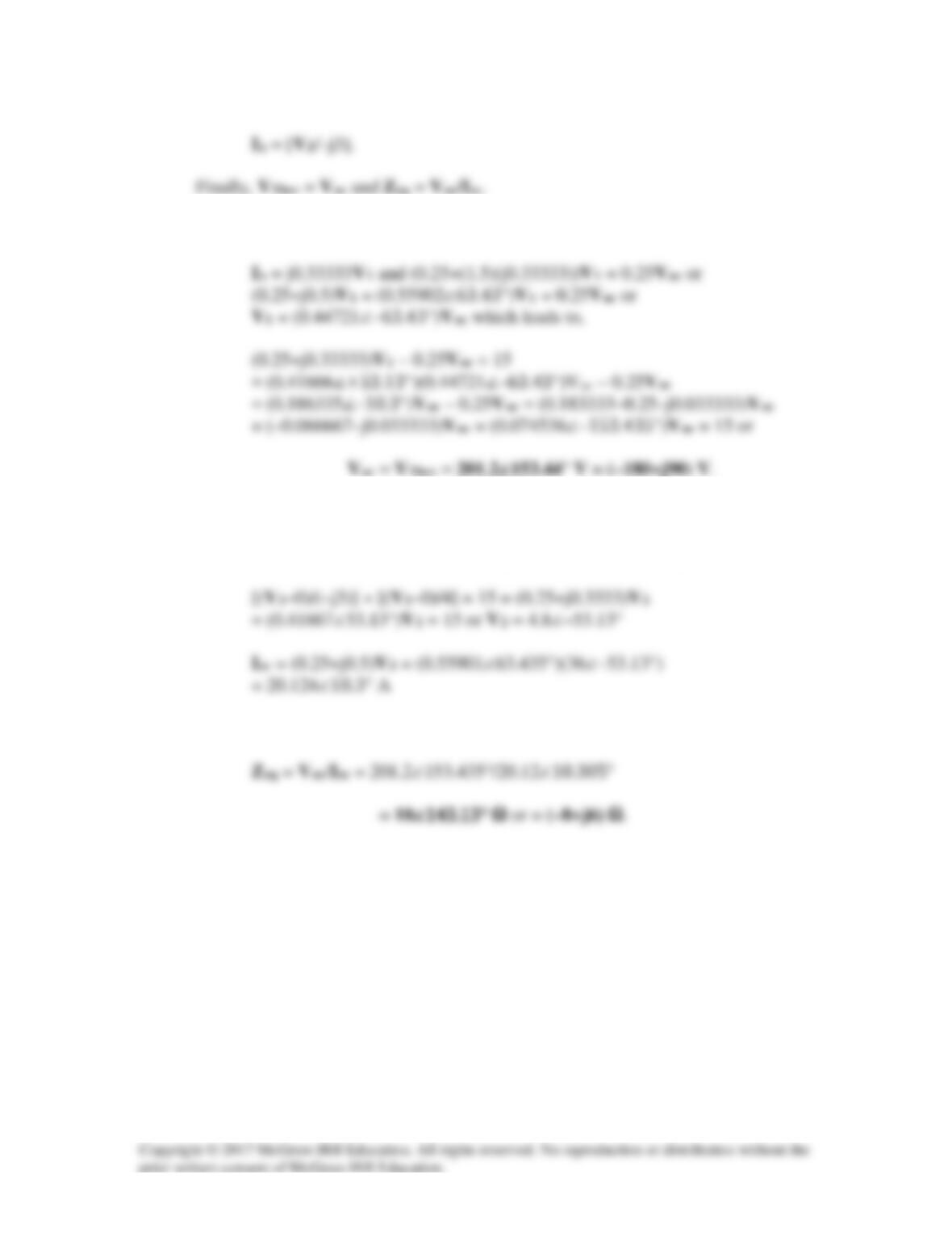
Step 2. Now all we need to do is to solve for the unknowns. For Voc,
Now for Isc,
Isc = [V2/4] + 1.5Ix = (0.25+(1.5)(j0.33333))V2 = (0.25+j0.5)V2.
Finally,
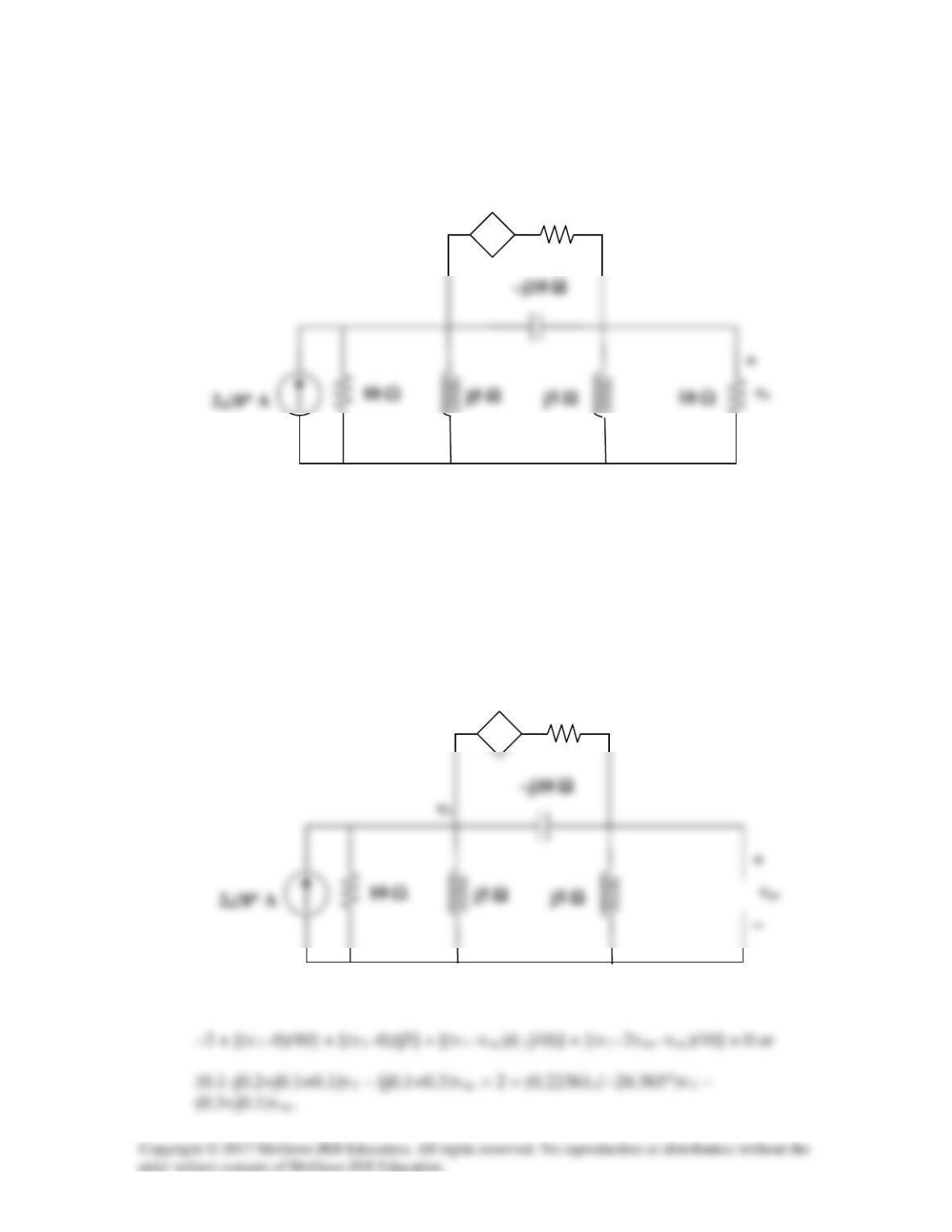
Solution 10.62
Using Thevenin’s theorem, find vo in the circuit in Fig. 10.105.
Figure 10.105
For Prob. 10.62.
Solution
We will take out the 10 Ω resistor and determine the Thevenin equivalent looking in from
the right. We will calculate Voc and Isc.
We now have two node equations, the first on at v1 is,
2vo
+ −
10 Ω
−
2voc
+ −
10 Ω
The second equation, at voc, is, [(voc–0)/j5] + [(voc–v1)/(–j10)] + [(voc–v1+2voc)/10] = 0
or
–(0.1+j0.1)v1 + (–j0.2+j0.1+ 0.3)voc or v1 = [(0.3–j0.1)/(0.14142∠45°)]voc
Now for Isc, we have essentially the same equations with voltage across the second
inductor equal to zero (a short circuit).
Thus we get, (0.22361∠–26.565°)v1 = 2 or v1 = 8.9441∠26.565°. From the above we
–j10 Ω
0 V
+ −
10 Ω
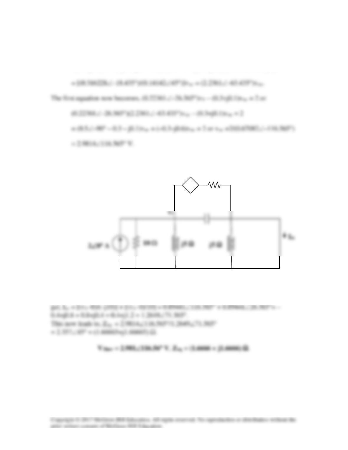
Solution 10.63
Obtain the Norton equivalent of the circuit depicted in Fig. 10.106 at terminals a–b.
Figure 10.106
For Prob. 10.63.
Solution
First we need to transform this circuit into the frequency domain (where the Norton
equivalent circuit exists) and then solve for Voc and Isc.
b
a
b
50 mH
10 Ω
a
j10 Ω
10 Ω
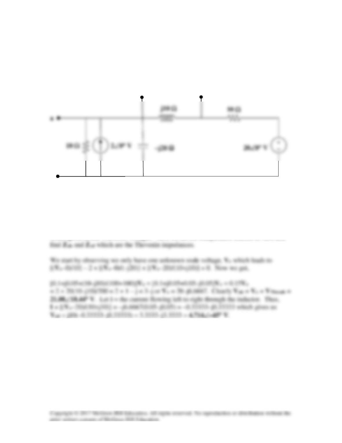
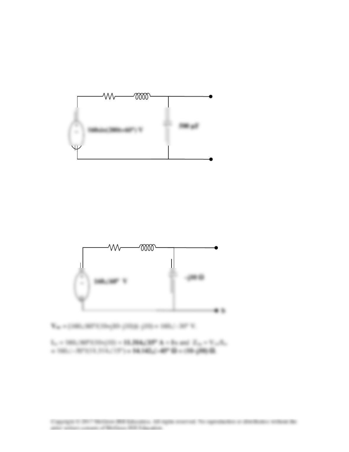
Solution 10.64
N
Z
is obtained from the circuit in Fig. (a).
40 Ω
-j30 Ω
To find
N
I
, consider the circuit in Fig. (b).
-j30 Ω
I2
For mesh 1,
For mesh 2,
60 Ω
40 Ω
I1
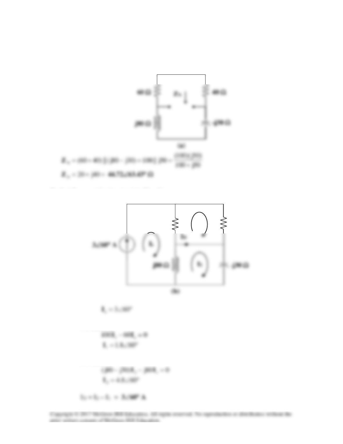
Solution 10.65
Using Fig. 10.108, design a problem to help other students to better understand Norton’s
theorem.
Problem
Compute io in Fig. 10.108 using Norton’s theorem.
Figure 10.108
Solution
2,05)t2cos(5=ω°∠→
To find
N
Z
, consider the circuit in Fig. (a).
(a)
2 Ω
To find
N
I
, consider the circuit in Fig. (b).
The Norton equivalent of the circuit is shown in Fig. (c).
Using current division,
10j50
)5j)(10j2)(131(
N
+
−
Z
Therefore,
=
o
i
542 cos(2t – 77.47°) mA
5∠0° V
2 Ω
Io
(c)
Solution 10.66
To find
th
Z
, consider the circuit in Fig. (a).
(a)
To find
th
V
and
N
I
, consider the circuit in Fig. (b).
-j10 Ω
Vx
-j10 Ω
(b)
Thus,
20j188–)105j10( −=− I
Solution 10.67
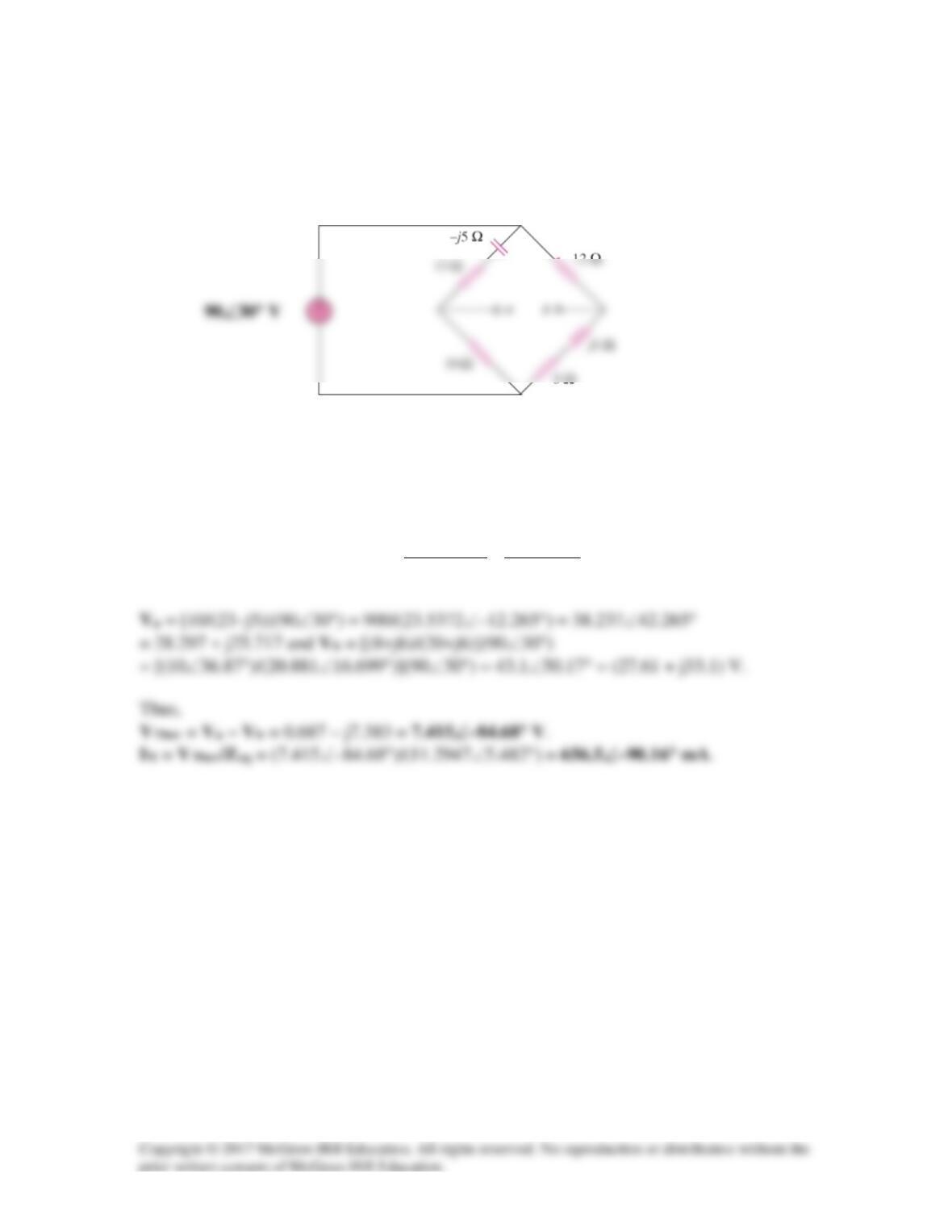
Find the Thevenin and Norton equivalent circuits at terminals a–b of the circuit in
Fig. 10.110.
Figure 10.110
For Prob. 10.67.
Solution
Zeq =
620
)68(12
523
)513(10
)68//(12)513//(10 j
j
j
j
jj +
+
+
−
−
=++−
= (11.243 + j1.079) Ω.
Solution 10.68
For the circuit in Fig. 10.111, obtain the Thèvenin equivalent at terminals a–b.
Figure 10.111
For Prob. 10.68.
Solution
20
We obtain VTh using the circuit below.
Io 4
Ω
a
+ +
5.2j
)2j(10j
)2j//(10j −=
−
=−
Combining (1) and (2) gives
To find RTh, we insert a 1–A source at terminals a-b, as shown below.
Io 4
Ω
a
+
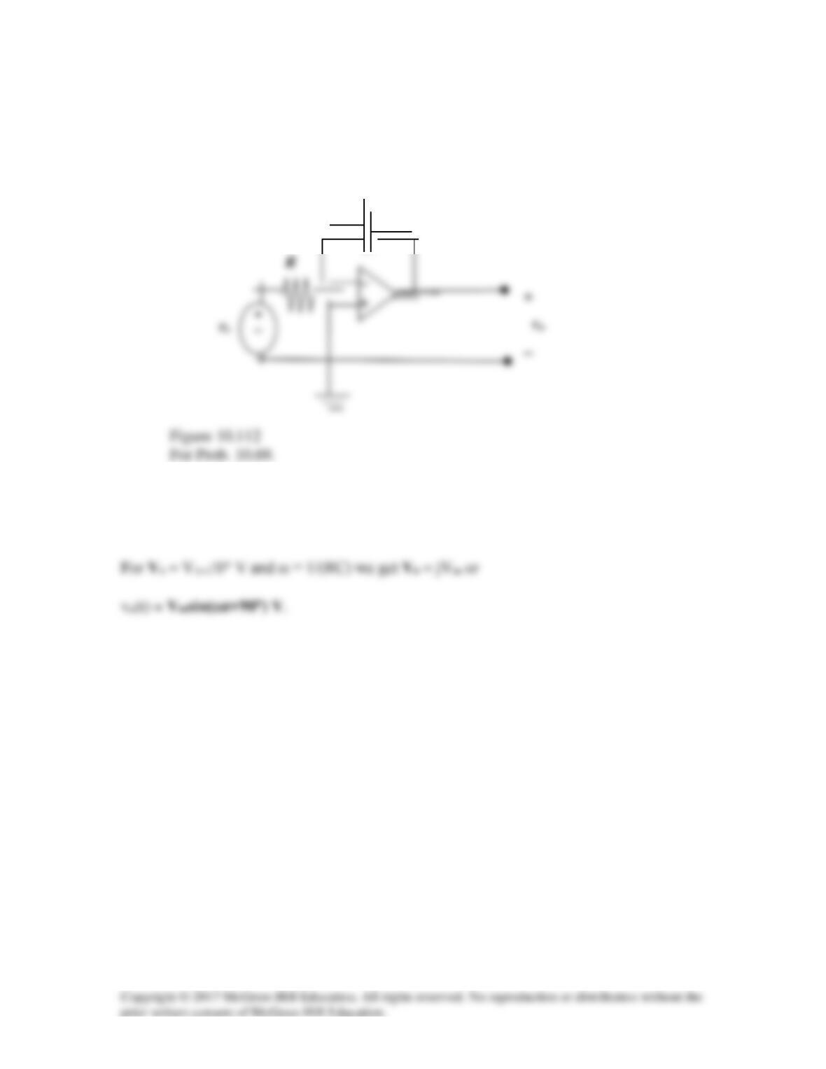
Solution 10.69
For the integrator shown in Fig. 10.112, obtain Vo/Vs. Find vo(t) when
vs(t) = Vm sin
ω
t and
ω
= 1/RC.
Solution
This is an inverting op amp so that Vo/Vs = –[1/(jωC)]/R = j[1/(ωRC)].
C
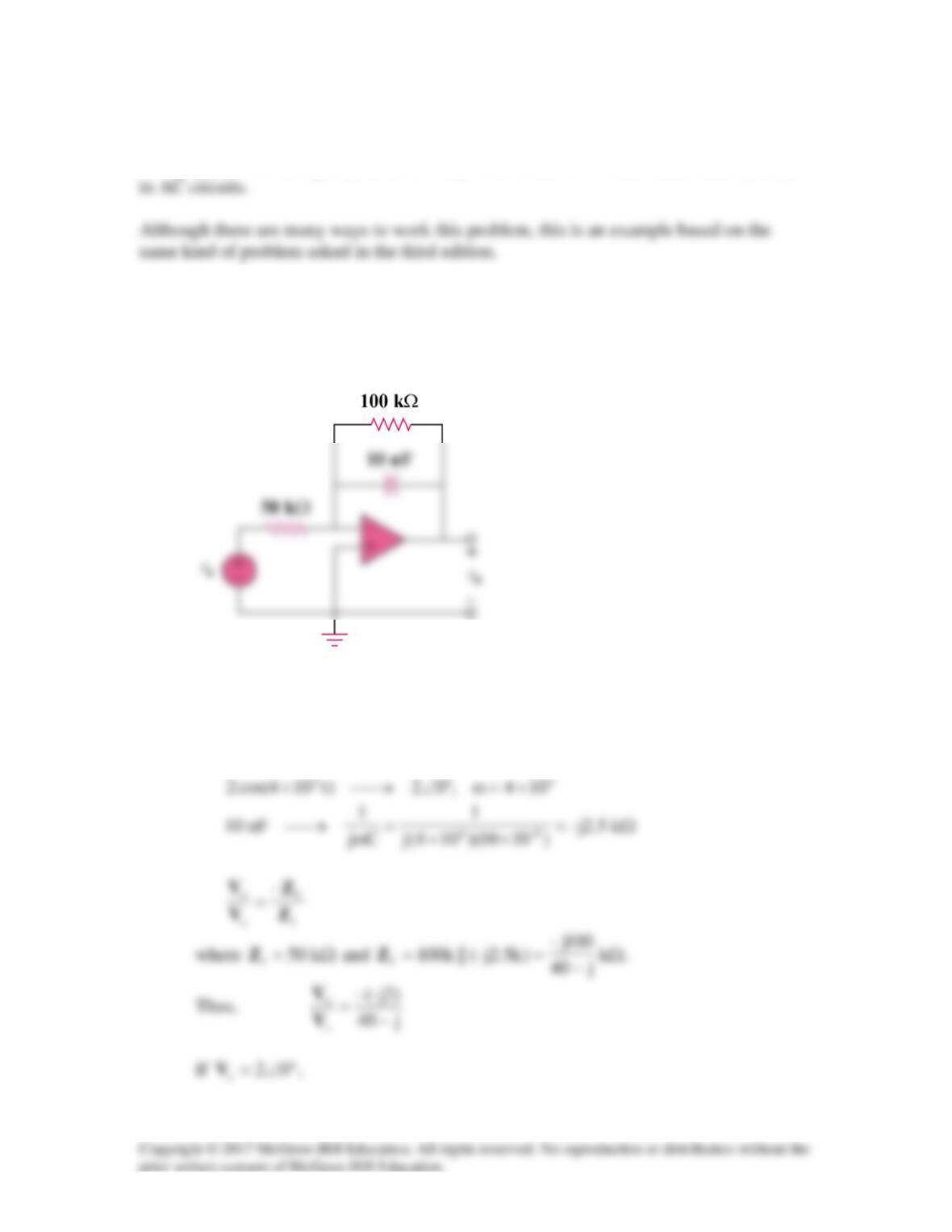
Solution 10.70
Using Fig. 10.113, design a problem to help other students to better understand op amps
Problem
The circuit in Fig. 10.113 is an integrator with a feedback resistor. Calculate vo(t) if
vs = 2 cos 4 × 10⁴t V.
Figure 10.113
Solution
This may also be regarded as an inverting amplifier.