Solution 16.19
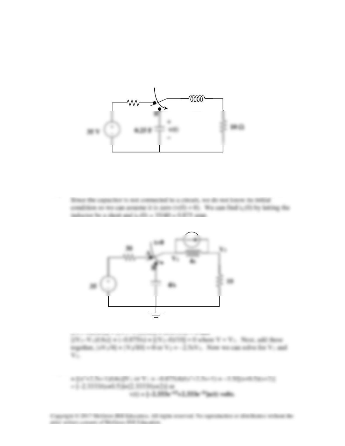
The switch in Fig. 16.42 moves from position A to position B at t=0 (please note that the
switch must connect to point B before it breaks the connection at A, a make before break
switch). Find v(t) for t >0.
B
Figure 16.42 For Prob. 16.19.
Solution
Step 1. First find all the initial conditions and then transform into the s-domain.
B
t=0
Step 2. [(s/4)+(1/(4s))+(2.5s/(4s))]V1 = –0.875/s
A
30 Ω
t=0
4 H
0.875/s
Solution 16.20
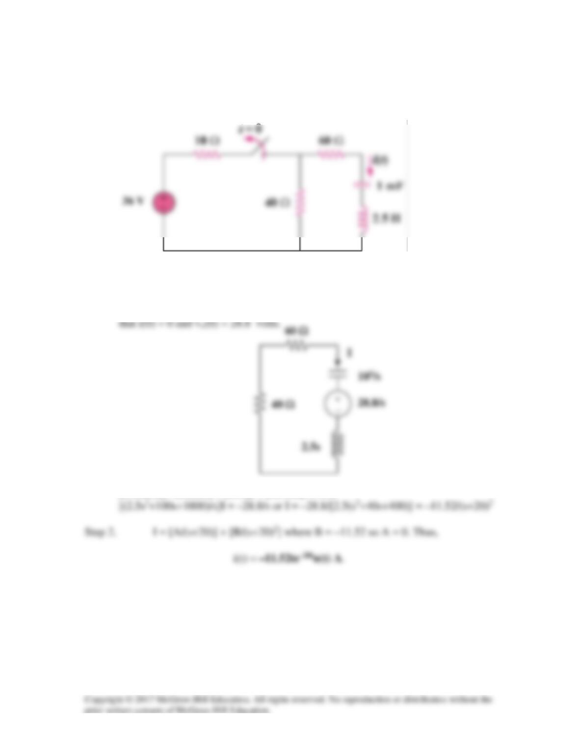
Find i(t) for t > 0 in the circuit of Fig. 8.43.
Figure 16.43
For Prob. 16.20.
Step 1. Convert the circuit into the s-domain and write one loop equation noting
[(1000/s)]I +[28.8/s] + [2.5s]I + [40+60]I = 0 or
Solution 16.21
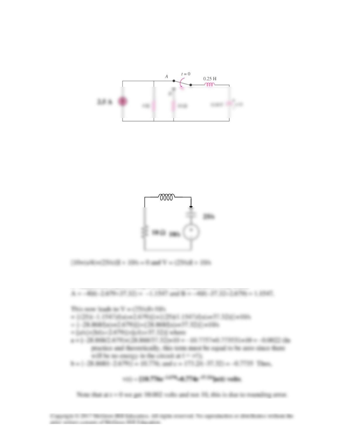
In the circuit of Fig. 16.44, the switch moves (make before break switch) from position A
to B at t = 0. Find v(t) for all t ≥ 0.
Figure 16.44 For Prob. 16.21.
Solution
Step 1. First we need to find our initial conditions, clearly i(0) = 0 and
v(0) = 4×2.5 = 10 volts. Next we convert the circuit into the s-domain. We can
then write a mesh equation and solve for v(t).
Step 2. I = –(10/s)/[ 10+(s/4)+(25/s)] = –(10/s){4s/[s2+40s+100]
= –40/[(s+2.679)(s+37.32)] = [A/(s+2.679)]+[B/(s+37.32)] where
I
s/4

V
Solution 16.22
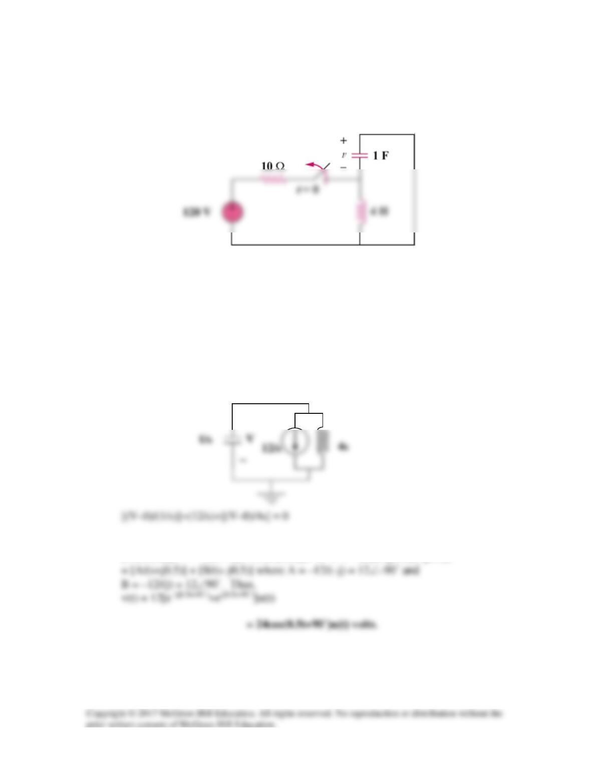
Find the voltage across the capacitor as a function of time for t > 0 for the circuit in
Fig. 16.45. Assume steady-state conditions exist at t = 0–.
Figure 16.45
For Prob. 16.22.
Solution
Step 1. First we need to calculate the initial conditions, vC(0) = 0 and
[(V–0)/1]+[12/s]+[(V–0)/(s/4)]+[(V–0)/(1/s)] = 0 then solve for V, next complete
a partial fraction expansion, and then convert back into the time domain.
+
Solution 16.23
Obtain v(t) for t > 0 in the circuit of Fig. 16.46.
Figure 16.46
For Prob. 16.23.
Solution
Step 1. First we need to calculate the initial conditions. Clearly since the inductor
looks like a short, v(0) = 0 and iL(0) = 120/10 = 12 amps. Next we convert the
circuit into the s-domain and solve for V and then obtain the partial fraction
expansion and convert back into the time domain.
Step 2.
[s+(1/(4s))]V = –12/s = [(s2+0.25)/(4s)]V or V = –12/[(s+j0.5)(s–j0.5)]
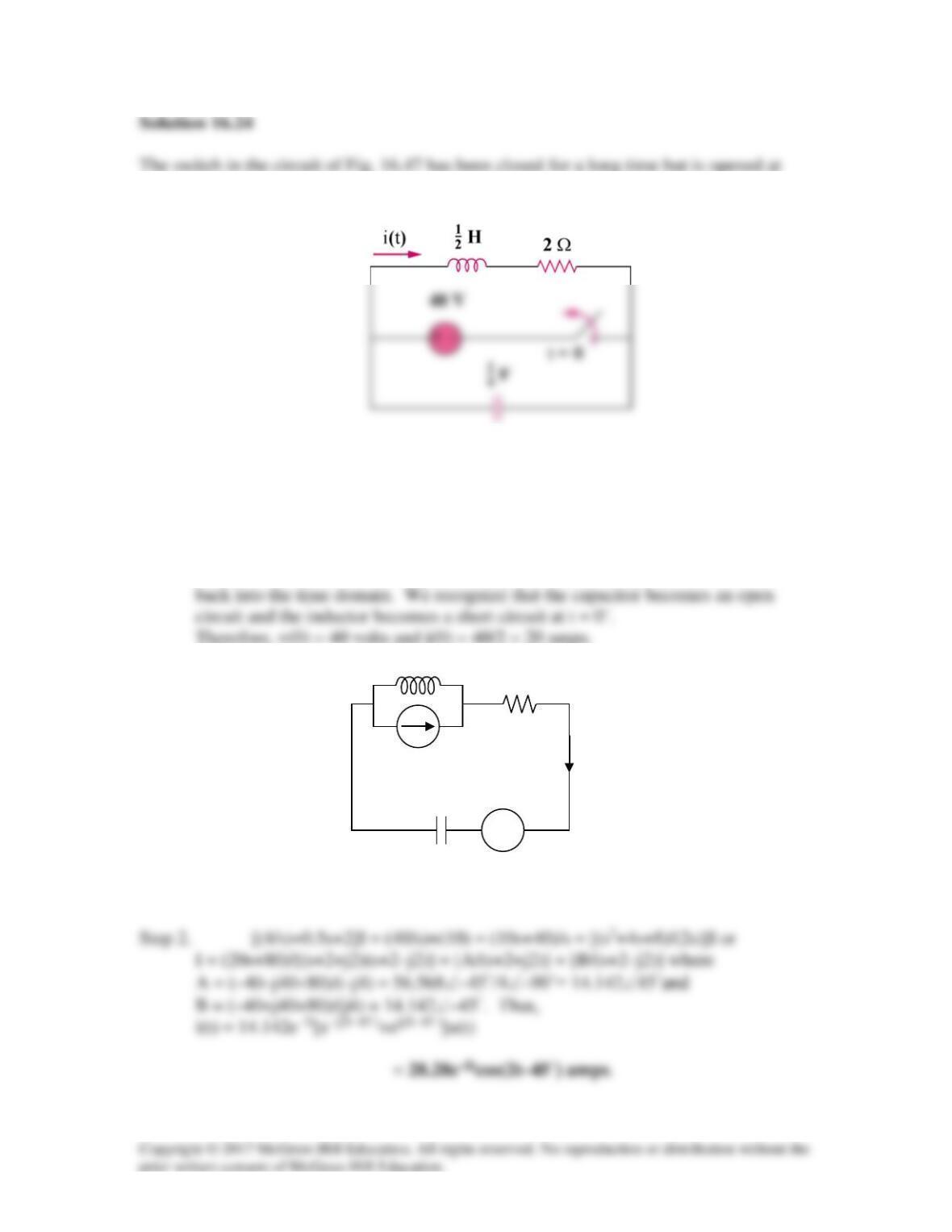
t = 0. Determine i(t) for t > 0.
Figure 16.47
For Prob. 16.24.
Solution
Step 1. First we solve for the initial conditions and then convert the circuit into the
s-domain and then solve for I, perform a partial fraction expansion, then convert
We can use mesh analysis, –(40/s) + (4/s)I + (0.5s)(I–20/s) + 2I = 0.
2
0.5s
20/s
4/s
+ −
40/s
I
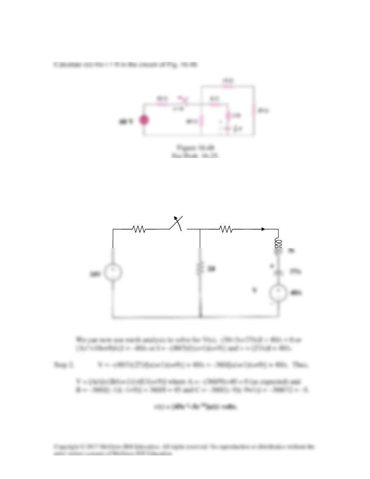
Solution 16.25
Step 1. First solve for the initial conditions. Then simplify the circuit and then
convert it into the s-domain and then solve for v(t). Since the capacitor becomes
an open circuit, iL(0) = 0 and v(0) = (60)24/36 = 40 volts.
6
I
t = 0
12 Ω
V
I
10
Solution 16.26
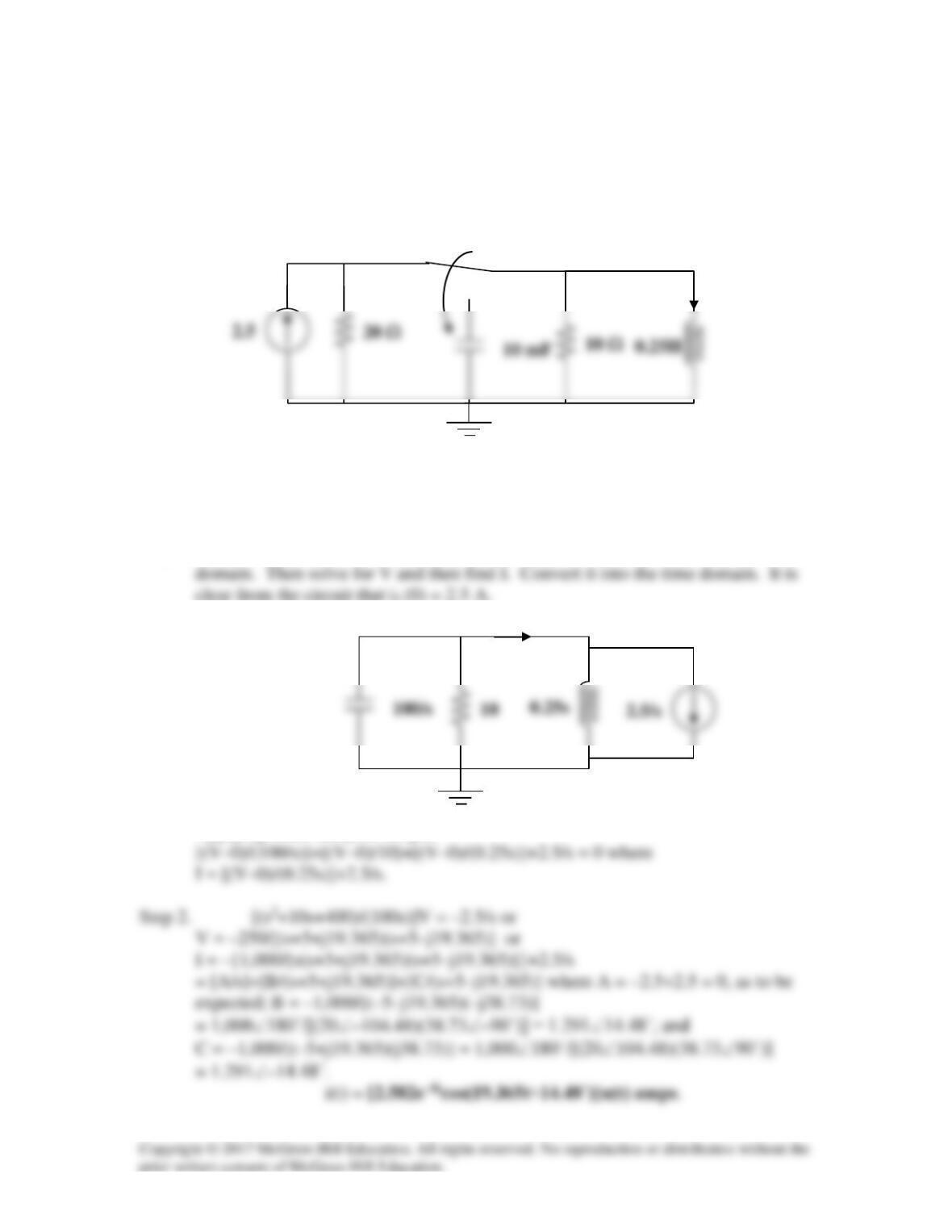
The switch in Fig. 16.49 moves from position A to position B at t=0 (please note that the
switch must connect to point B before it breaks the connection at A, a make before break
switch). Determine i(t) for t >0. Also assume that the initial voltage on the capacitor is
zero.
Figure 16.49 For Prob. 16.26.
Solution
Step 1. Determine the initial conditions and then convert the circuit into the s–
Applying nodal analysis we get,
i(t)
B
A
t = 0
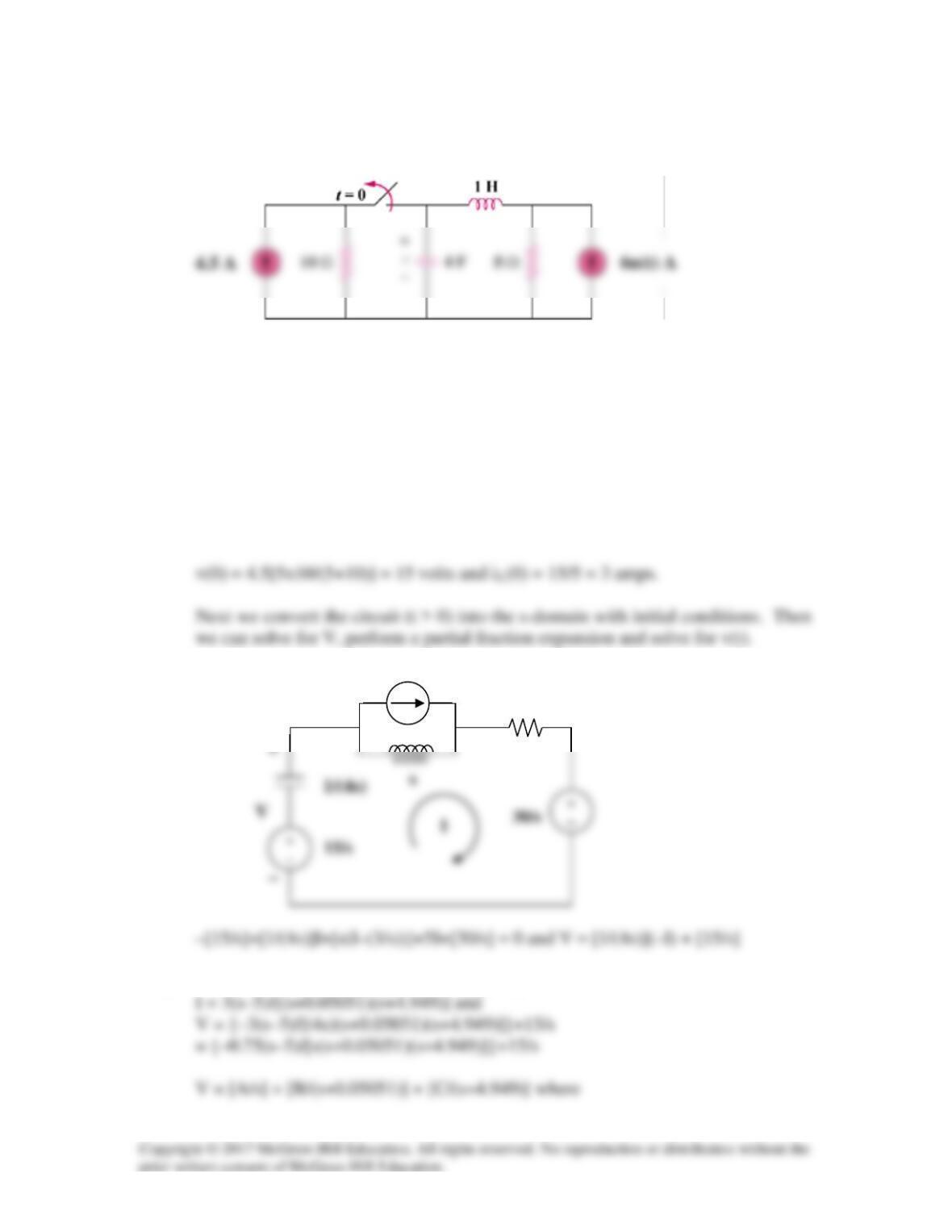
Solution 16.27
Find v(t) for t > 0 in the circuit in Fig. 16.50.
Figure 16.50
For Problem 16.27.
Solution
Step 1. First we need to determine the initial conditions. We note that the source
on the right is equal to zero until the switch opens. So, all initial conditions come
from the 4.5-amp source on the left. Since the capacitor looks like an open and
the inductor looks like a short we get,
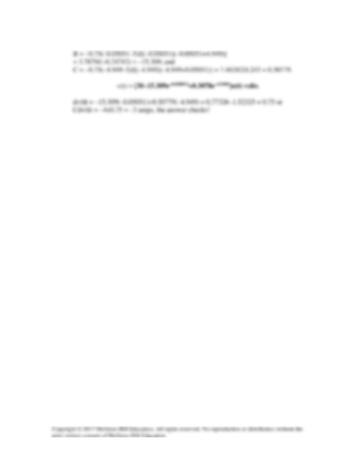
Step 2. {[1/(4s)]+s+5}I = {[s2+5s+0.25]/(s)}I = 3–15/s = 3(s–5)/s or
5 Ω
3/s
A = [3.75/[(0.05051)(4.949)]]+15 = 30;
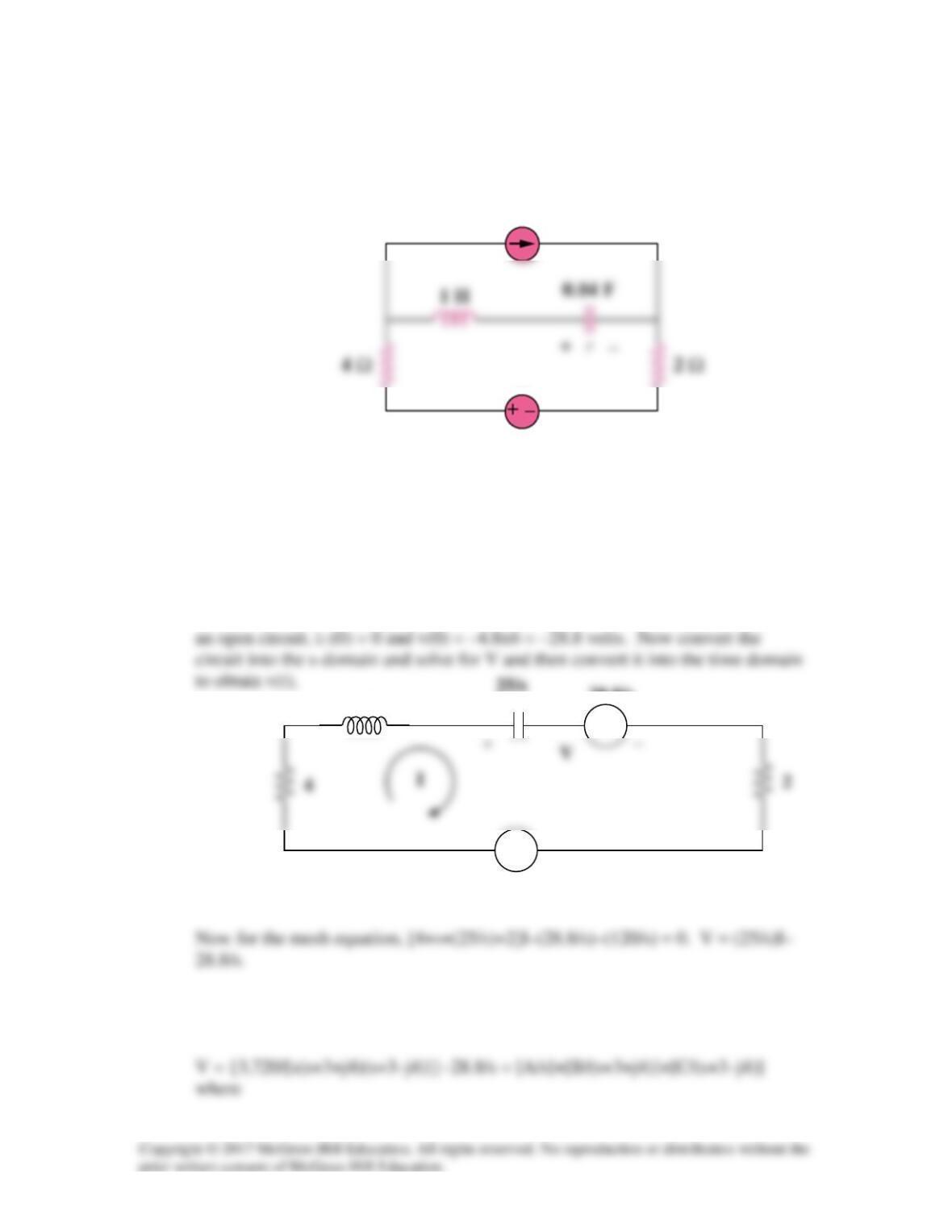
Solution 16.28
For the circuit in Fig. 16.51, find v(t) for t > 0.
Figure 16.51
For Prob. 16.28.
Solution
Step 1. Determine the initial conditions (at t = 0, the 4.8 amp current source turns
off and the 120 volt voltage source becomes active). Since the capacitor becomes
V
Step 2.
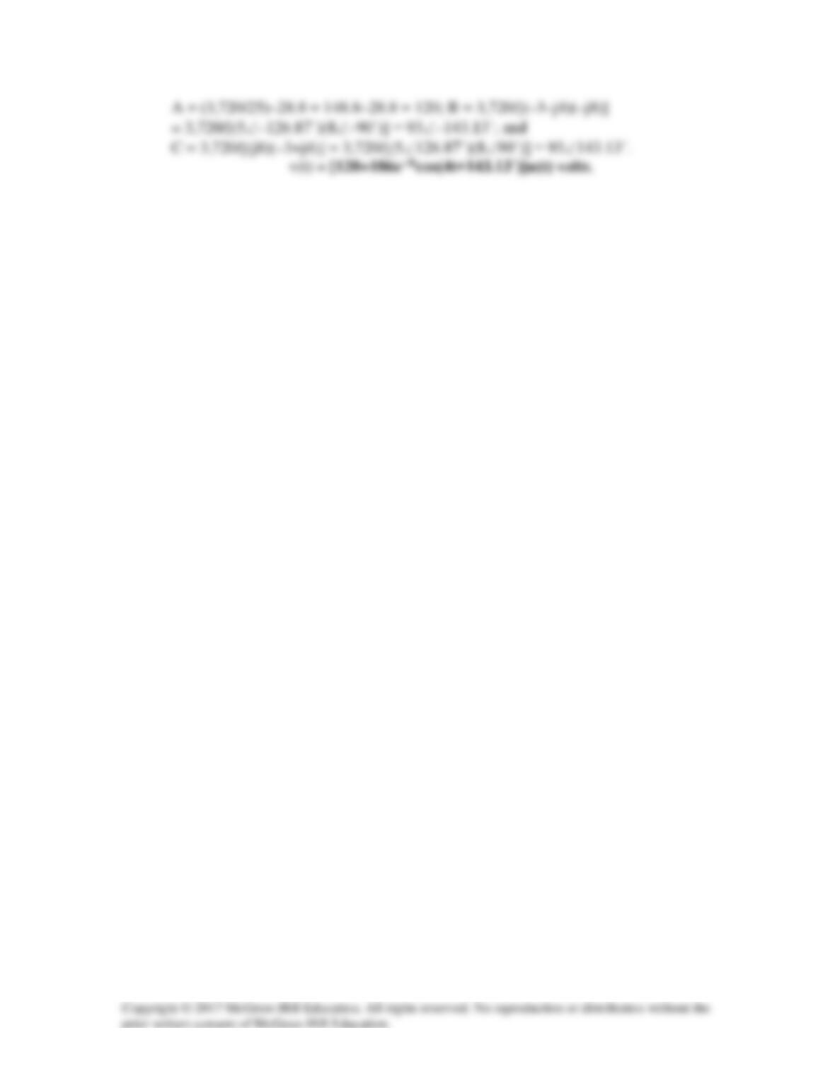
[(s2+6s+25)/s]I = 148.8/s or I = 148.8/(s2+6s+25) = 148.8/[(s+3+j4)(s+3–j4)] thus,
4.8(1–u(t)) A
120u(t) V
+ −
120/s
s
− +
28.8/s
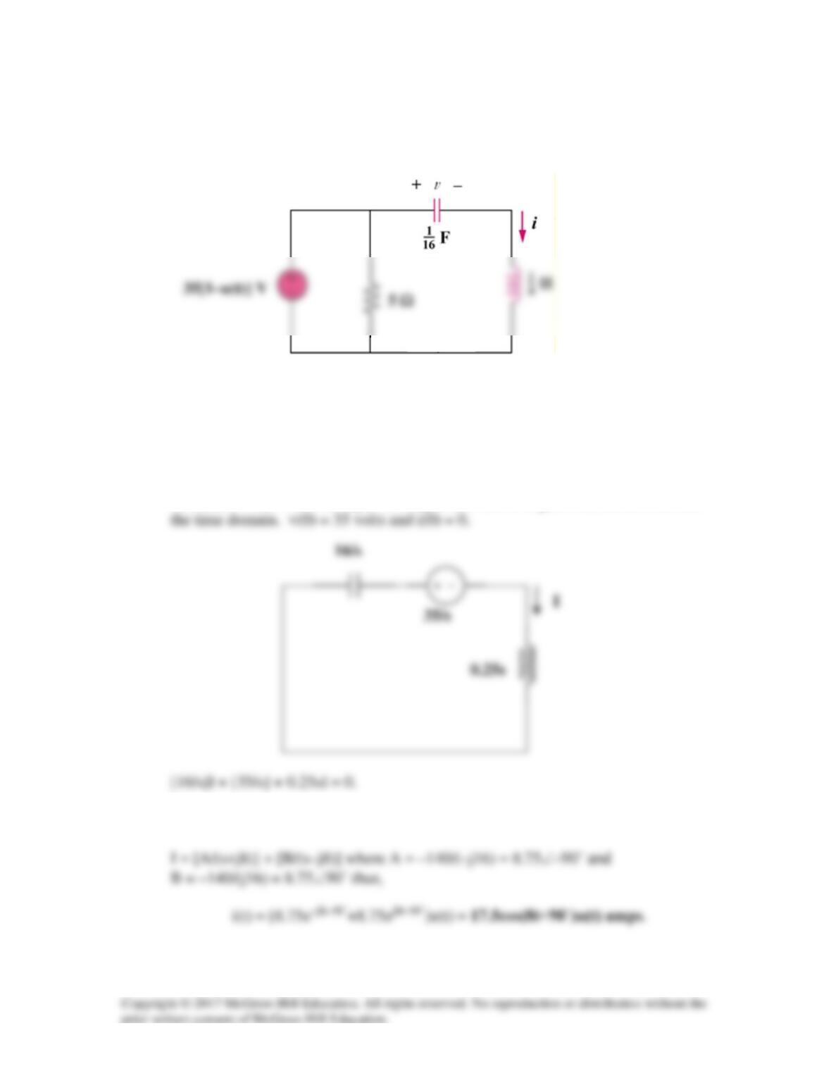
Solution 16.29
Calculate i(t) for t > 0 in the circuit in Fig. 16.52.
Figure 16.52
For Prob. 16.29.
Solution
Step 1. Calculate the initial conditions and then convert the above circuit into the
s-domain. Then solve for I, perform a partial fraction expansion, and convert into
Step 2. {[16/s]+0.25s}I = –35/s = {[s2+64]/(4s)}I or I = –140/[(s+j8)(s–j8)] or
Solution 16.30
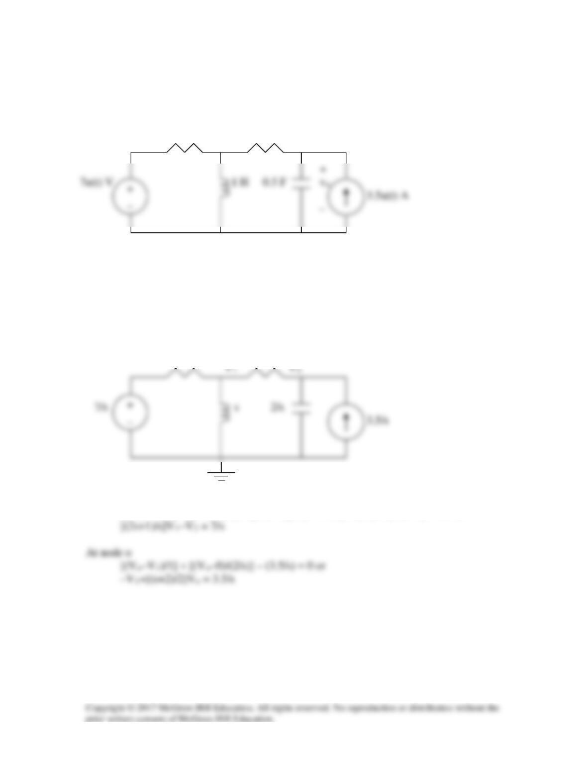
Find vo(t), for all t>0, in the circuit of Fig. 16.53.
1 Ω 1 Ω
Figure 16.53
For Prob. 16.30.
Solution
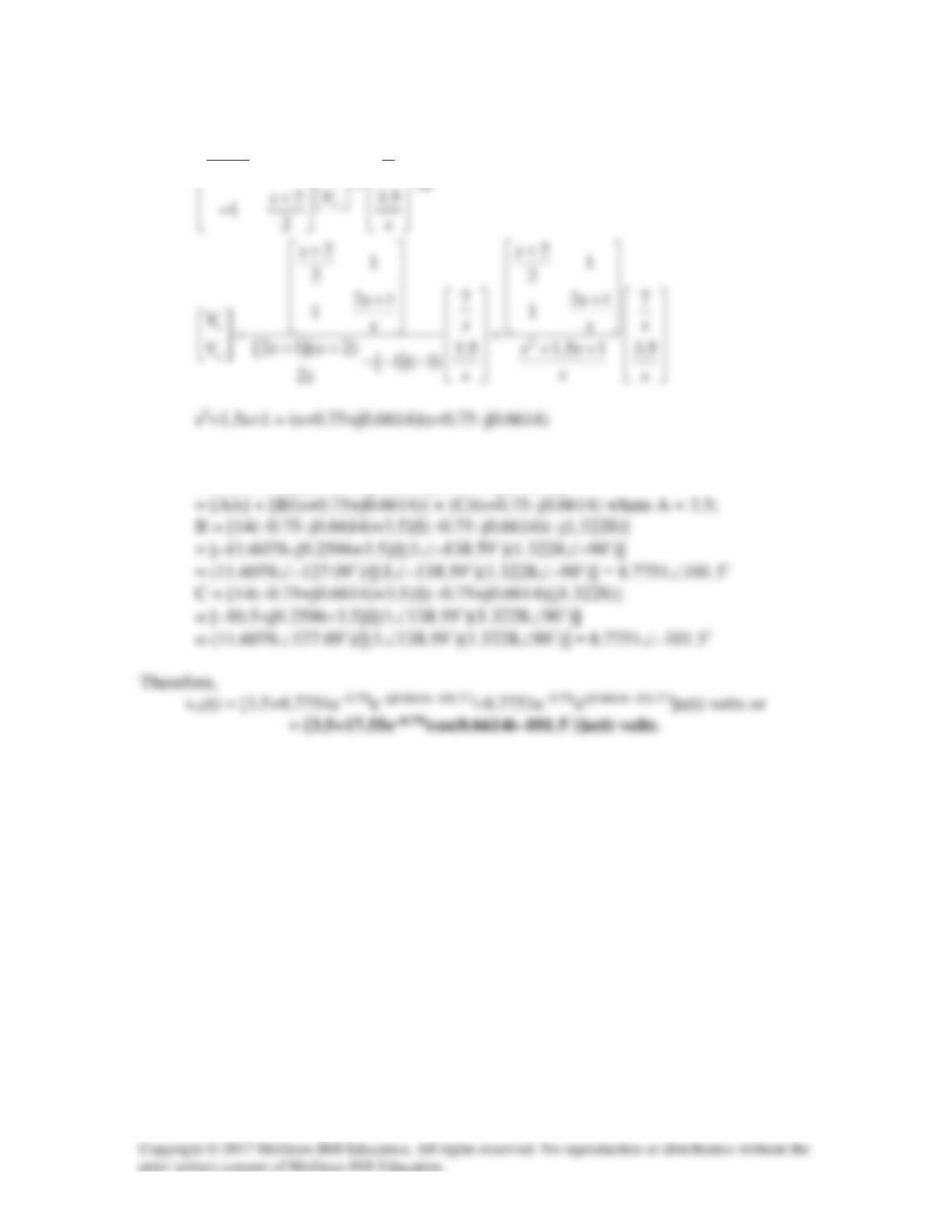
The circuit in the s-domain is shown below. Please note, iL(0) = 0 and vo(0) = 0
because both sources were equal to zero for all t<0.
1 1
At node 1
[(V1–7/s)/1] + [(V1–0)/s] + [(V1–V2)/1] = 0 or [1+(1/s)+1]V1–V2 = 7/s or
In matrix form we get,
1
7
21 1
s
Vs
s
+
−
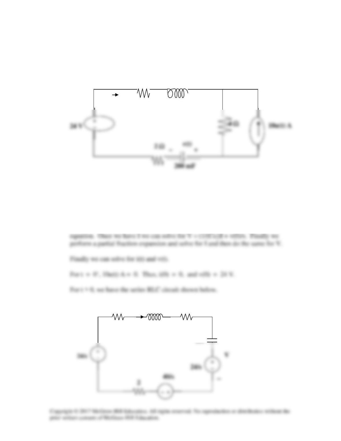
Vo = s[(7/s)+[(2s+1)3.5]/s2]/[(s+0.75+j0.6614)(s+0.75–j0.6614)]
= (14s+3.5)/[s(s+0.75+j0.6614)(s+0.75–j0.6614)]
Solution 16.31
Obtain v(t) and i(t) for t > 0 in the circuit in Fig. 16.54.
Figure 16.54
For Prob. 16.31.
Solution
Step 1. First we need to determine the initial conditions. Then, we need to
convert the circuit into the s-domain. We then can solve for I using a mesh
5 H
2 Ω
i(t)
I
4
5s
+
5/s
2
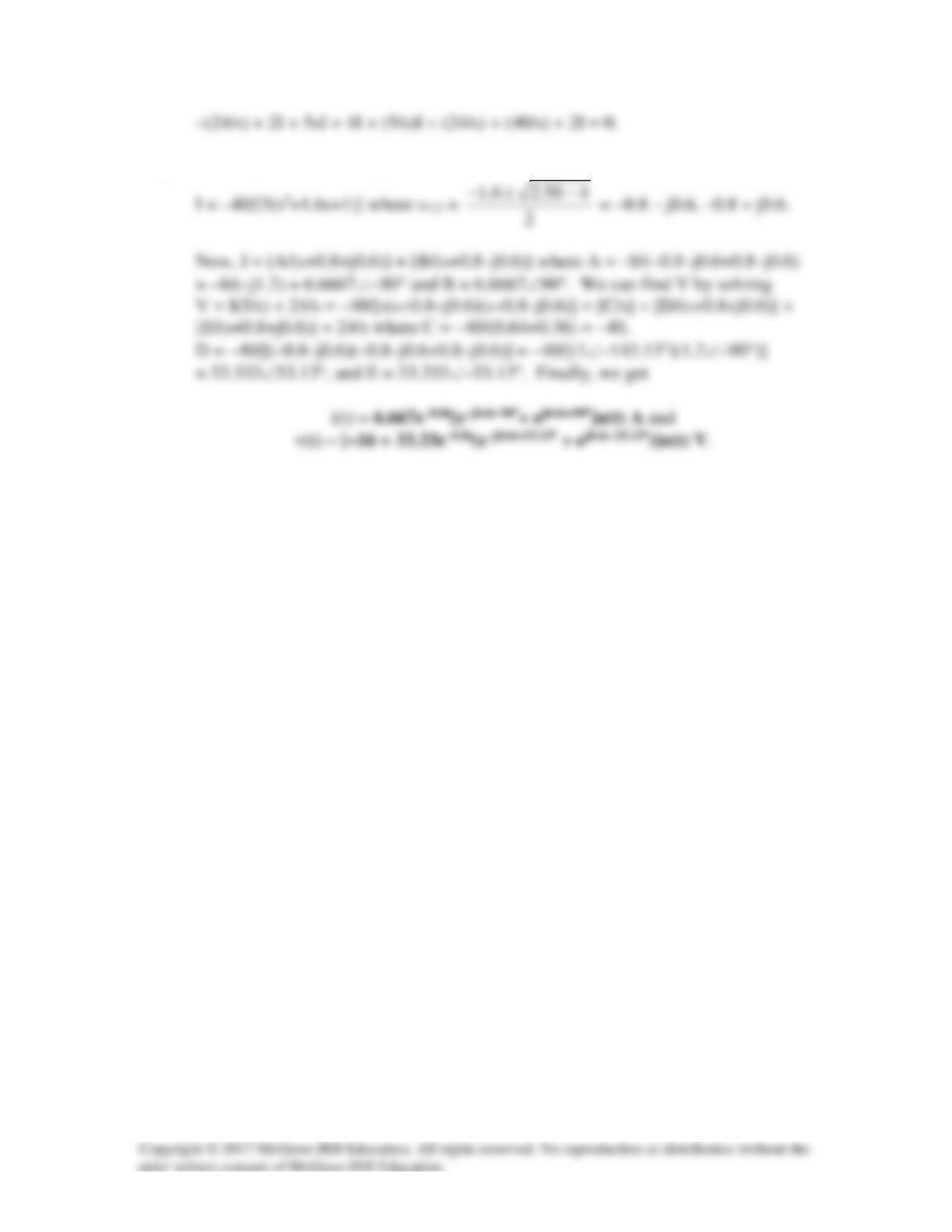
Step 2. [5s+2+4+2+(5/s)]I = –40/s = [(5s2+8s+5)/s]I or
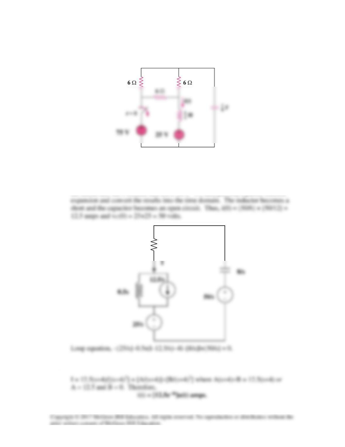
Solution 16.32
For the network in Fig. 16.55, solve for i(t) for t > 0.
Figure 16.55 For Prob. 16.32.
Solution
Step 1. First we need to find all the initial conditions. Then we need to transform
the circuit into the s-domain and solve for I. We then perform a partial fraction
Step 2. [0.5s+4+8/s]I = [(s2+8s+16)/(2s)]I = –[25/s]+6.25+50/s = (s+4)/(0.16s) or
4 Ω
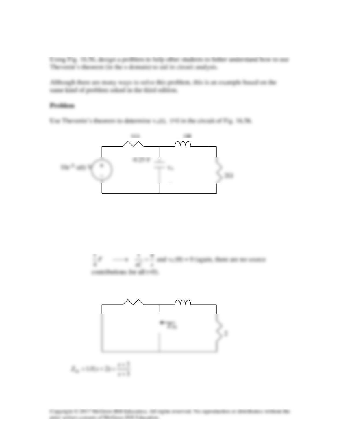
Solution 16.33
+
–
Figure 16.56 For Prob. 16.33.
Solution
11Hs →
and iL(0) = 0 (the sources is zero for all t<0).
To find ZTh , consider the circuit below.
1 s
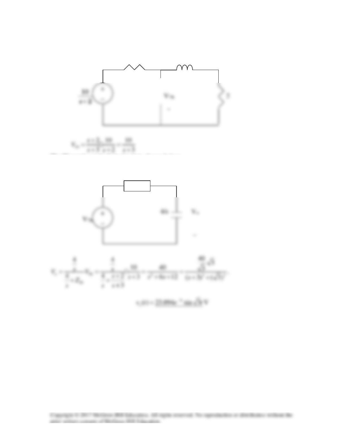
To find VTh, consider the circuit below.
1 s
+
The Thevenin equivalent circuit is shown below
ZTh
+