Solution 8.71
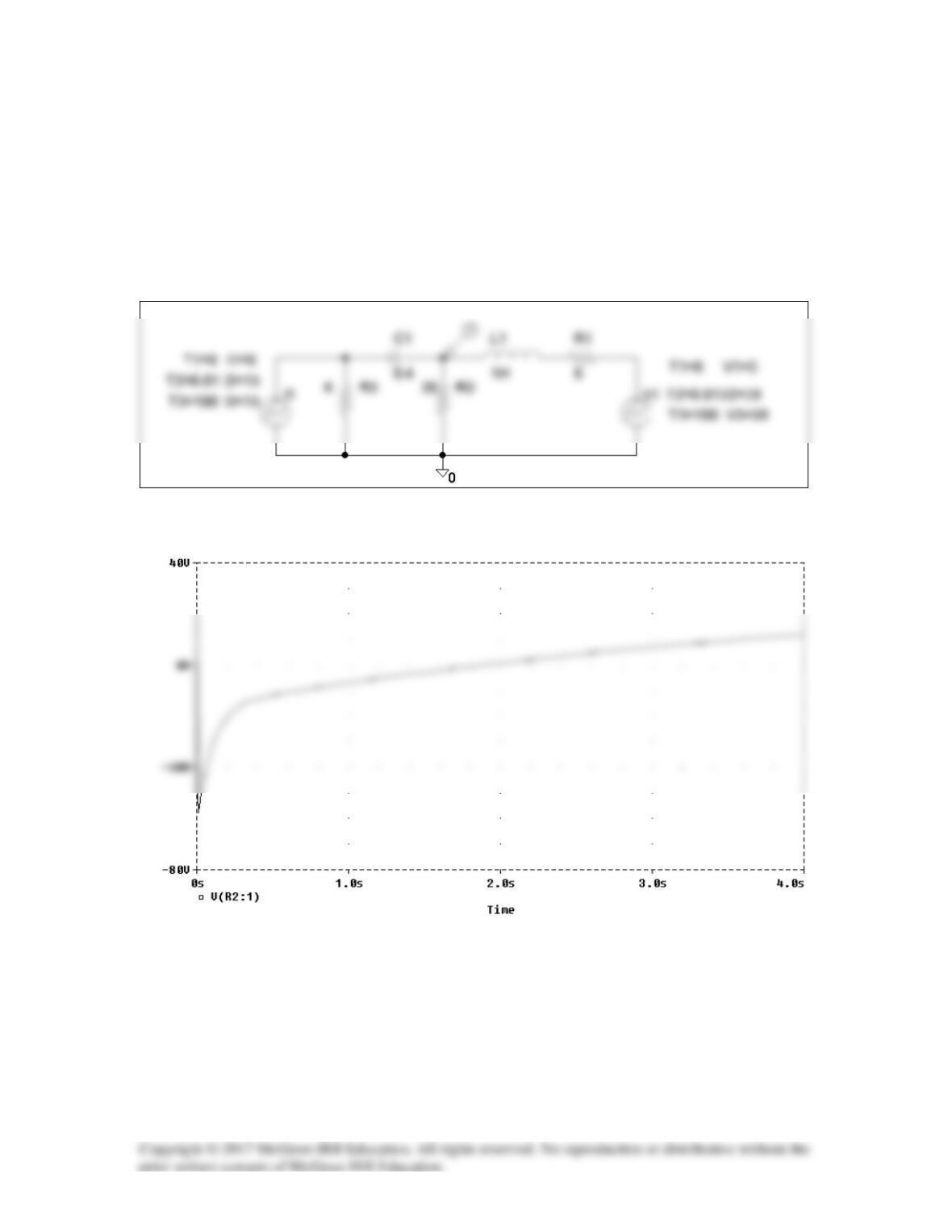
The schematic is shown below. We use VPWL and IPWL to model the 39 u(t) V and 13
u(t) A respectively. We set Print Step to 25 ms and Final Step to 4s in the Transient
box. A voltage marker is inserted at the terminal of R2 to automatically produce the plot
of v(t) after simulation. The result is shown below.
Solution 8.72
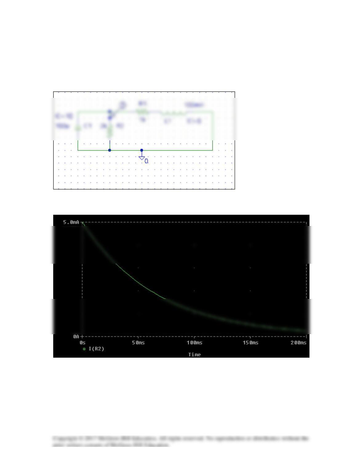
When the switch is in position 1, we obtain IC=10 for the capacitor and IC=0 for the
inductor. When the switch is in position 2, the schematic of the circuit is shown below.
When the circuit is simulated, we obtain i(t) as shown below.
Solution 8.73
Design a problem, using PSpice, to help other students to better understand source-free
RLC circuits.
Problem
The step response of an RLC circuit is given by
Solution
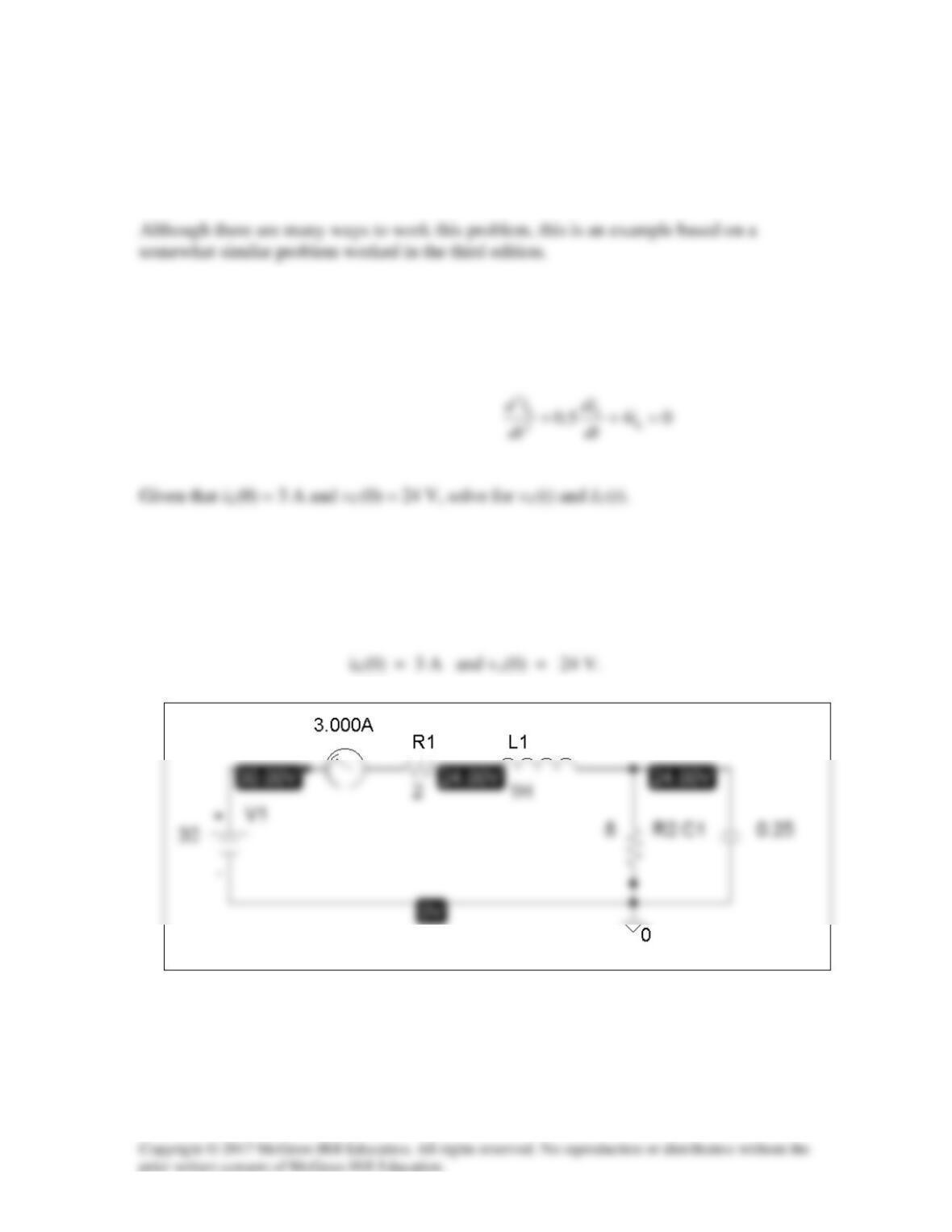
(a) For t < 0, we have the schematic below. When this is saved and simulated, we
obtain the initial inductor current and capacitor voltage as
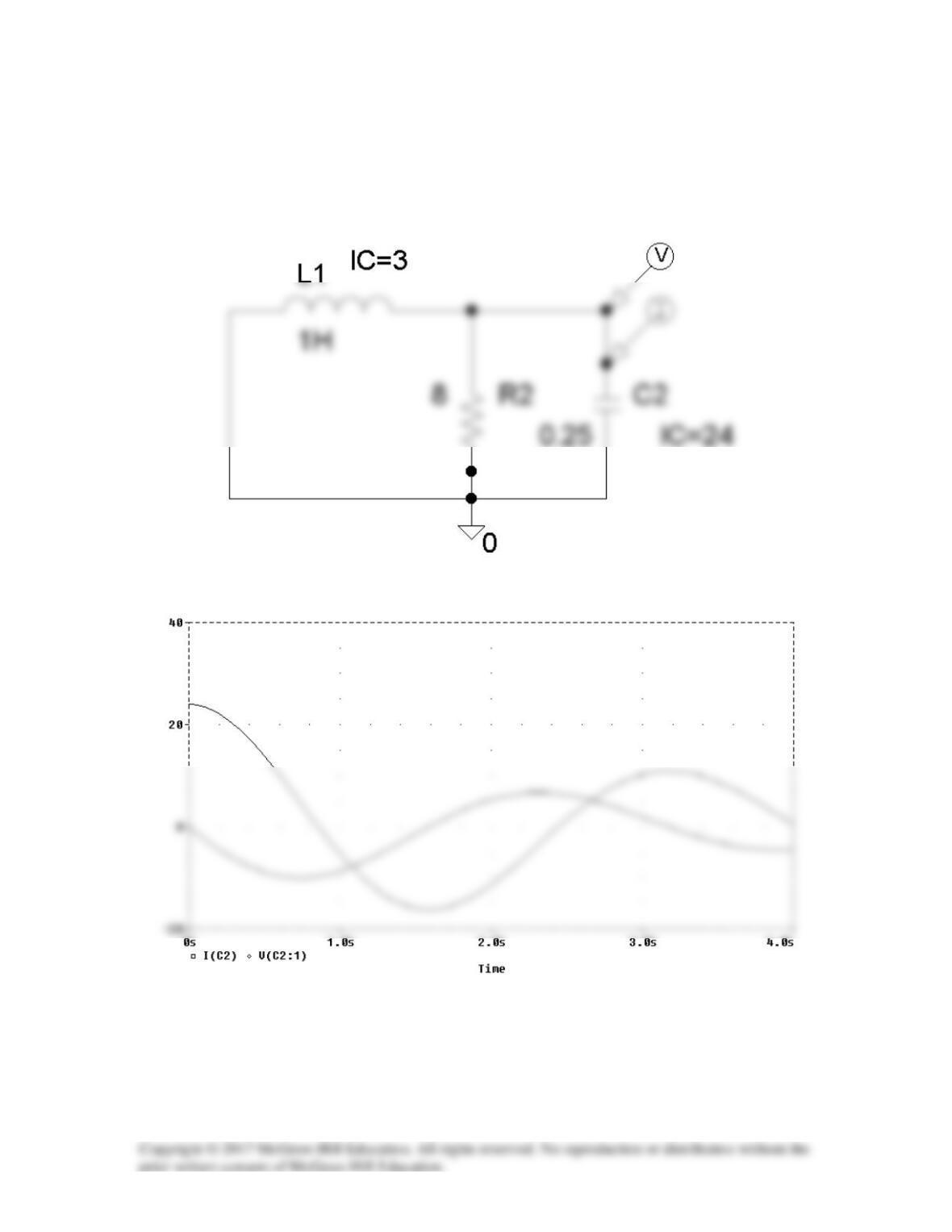
(b) For t > 0, we have the schematic shown below. To display i(t) and v(t), we
insert current and voltage markers as shown. The initial inductor current and capacitor
voltage are also incorporated. In the Transient box, we set Print Step = 25 ms and the
Final Time to 4s. After simulation, we automatically have io(t) and vo(t) displayed as
shown below.
Solution 8.74
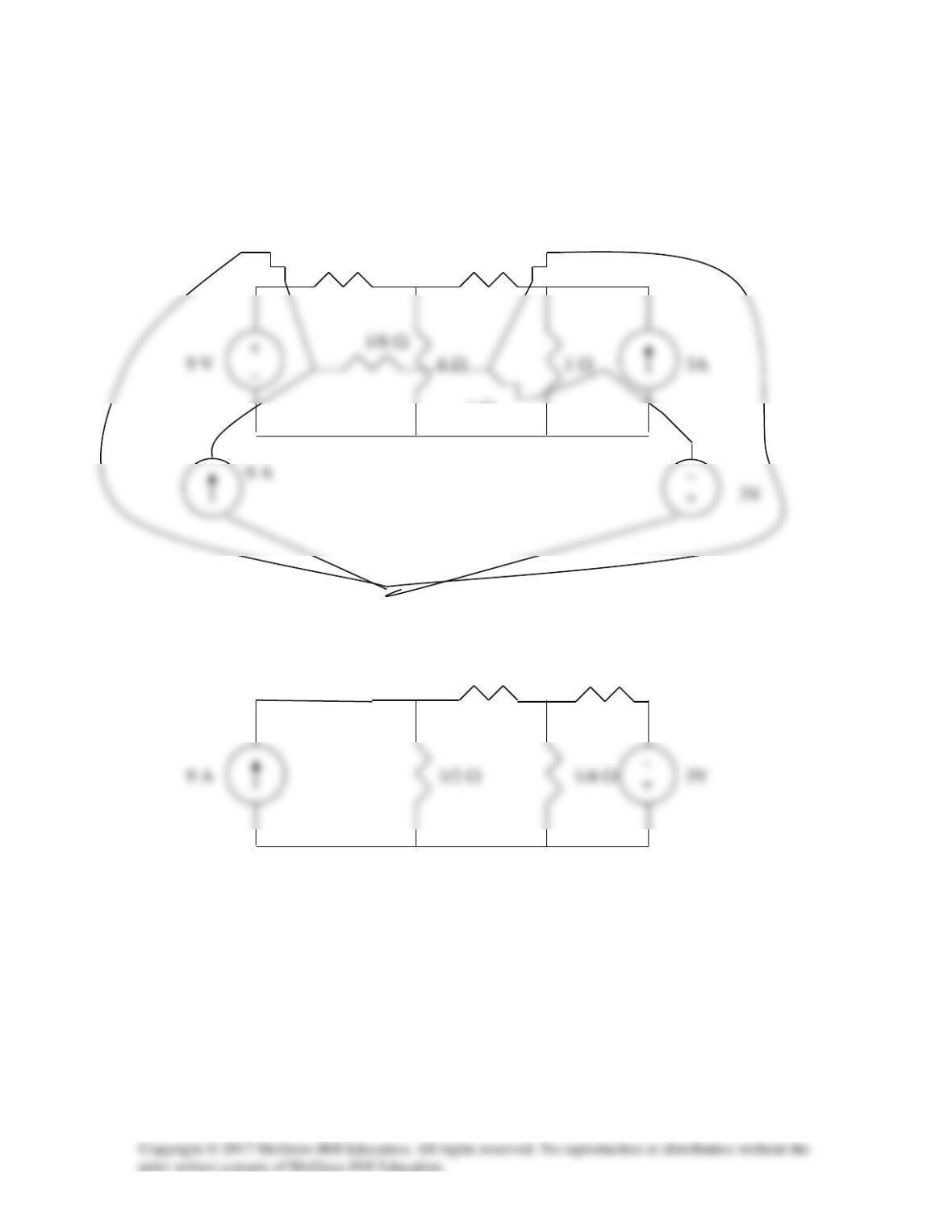
The dual is constructed as shown below.
0.5 Ω 0.25 Ω
2 Ω 4 Ω
1 Ω
The dual is redrawn as shown below.
1/6 Ω 1 Ω
Solution 8.75
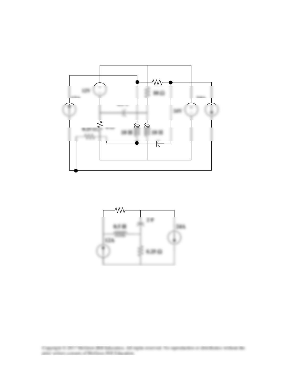
The dual circuit is connected as shown in Figure (a). It is redrawn in Figure (b).
24A
0.1 Ω
(a)
24A
12A
10 µF
0.1 Ω
(b)
Solution 8.76
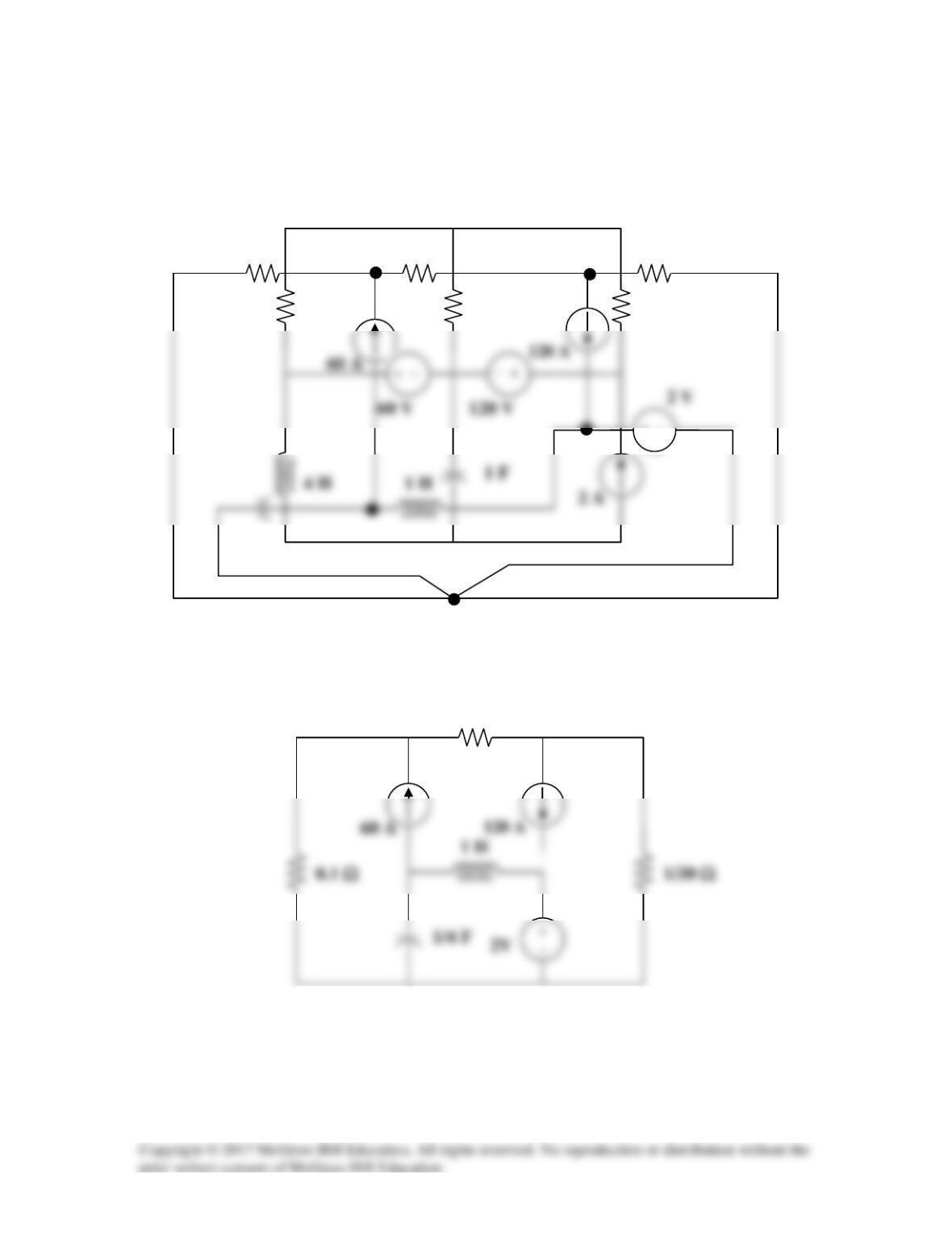
The dual is obtained from the original circuit as shown in Figure (a). It is redrawn in
Figure (b).
+ −
(b)
0.05 Ω
0.05 Ω
20 Ω
(a)
4F
0.1 Ω
10 Ω
1/3 Ω
30 Ω
+ −
Solution 8.77
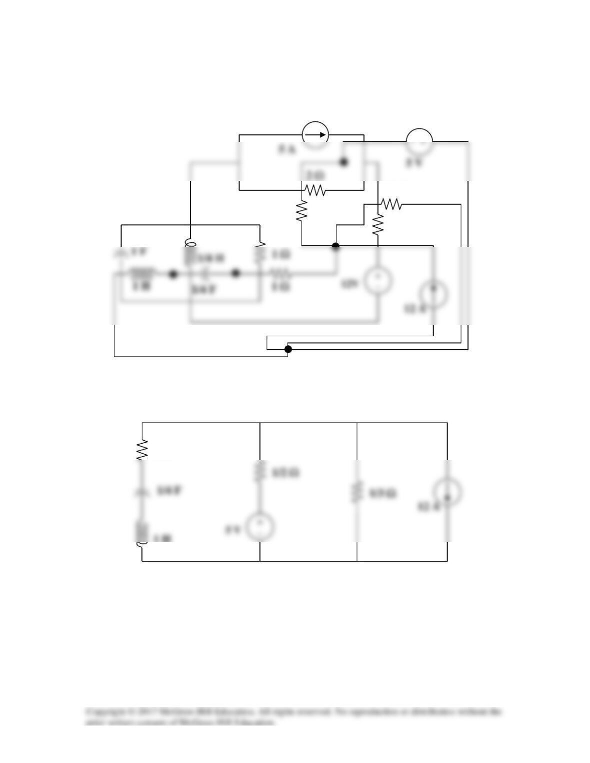
The dual is constructed in Figure (a) and redrawn in Figure (b).
2 Ω
1 Ω
1 Ω
1/3 Ω
1/2 Ω
(a)
1/2 Ω
3 Ω
1/3 Ω
(b)
1 Ω
1 H
Solution 8.78
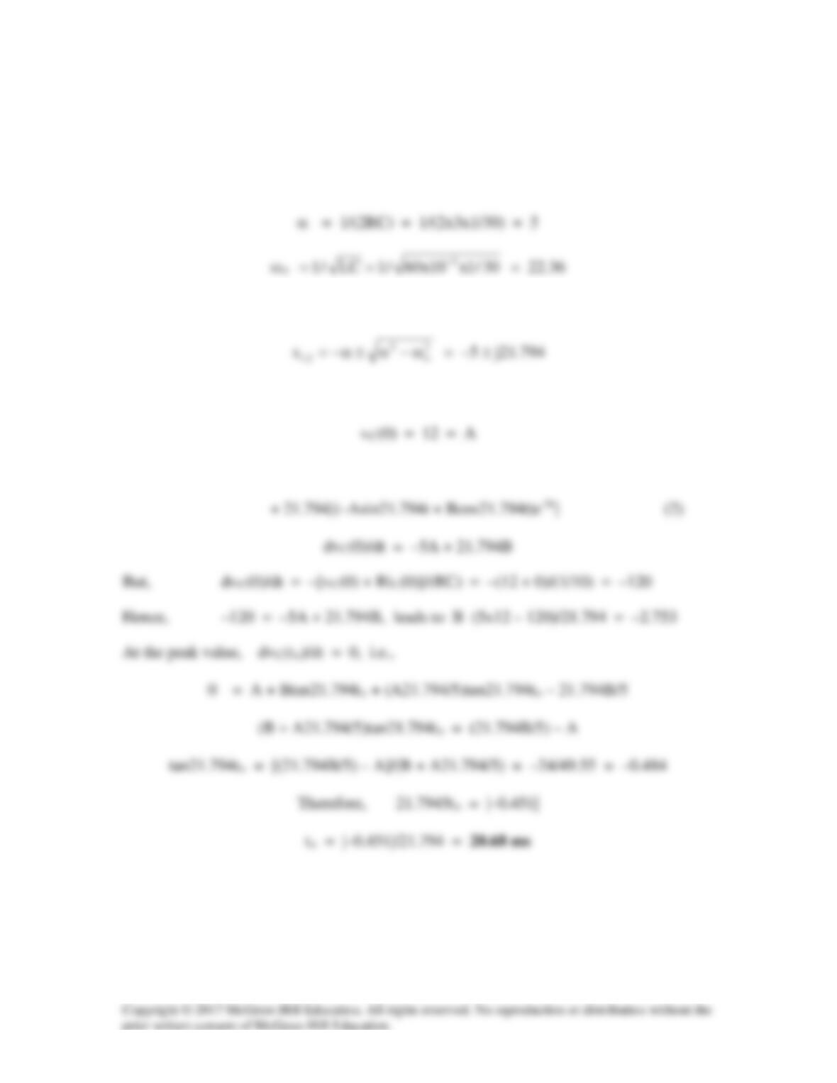
The voltage across the igniter is vR = vC since the circuit is a parallel RLC type.
vC(0) = 12, and iL(0) = 0.
α < ωo produces an underdamped response.
vC(t) = e–5t(Acos21.794t + Bsin21.794t) (1)
dvC/dt = –5[(Acos21.794t + Bsin21.794t)e–5t]
Solution 8.79
A load is modeled as a 100-mH inductor in parallel with a 12-Ω resistor. A capacitor is
needed to be connected to the load so that the network is critically damped at 60 Hz.
Calculate the size of the capacitor.
Solution
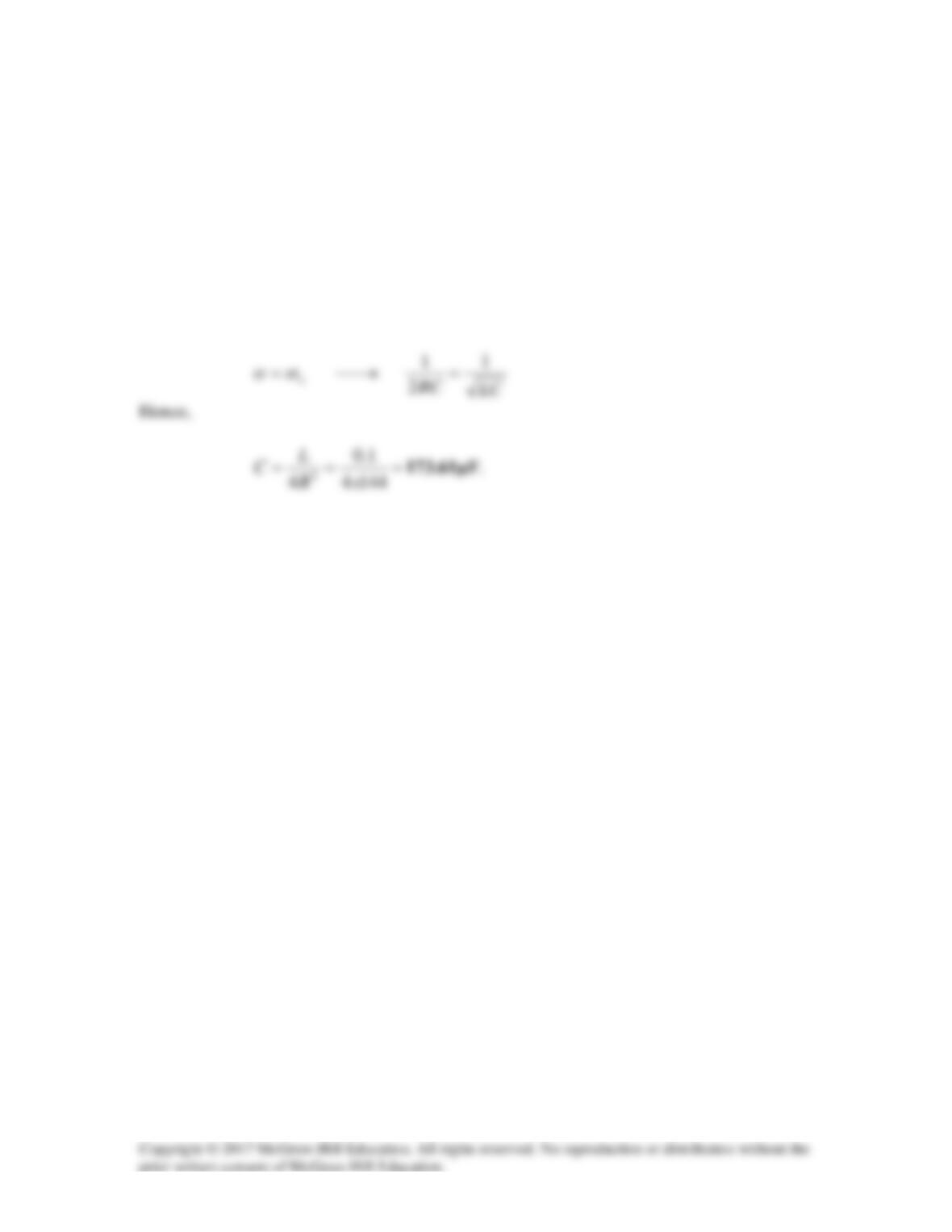
For critical damping of a parallel RLC circuit,
Solution 8.80
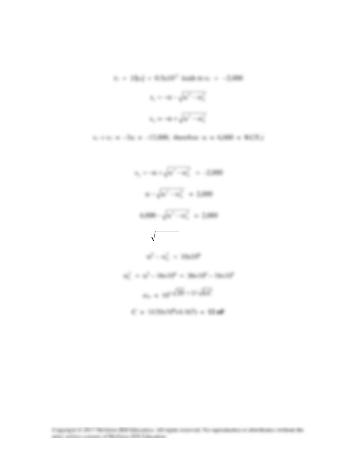
t1 = 1/|s1| = 0.1×10⁻³ leads to s1 = –1000/0.1 = –10,000
L = R/12,000 = 50,000/12,000 = 4.167H
2
o
2
ω−α
= 4,000
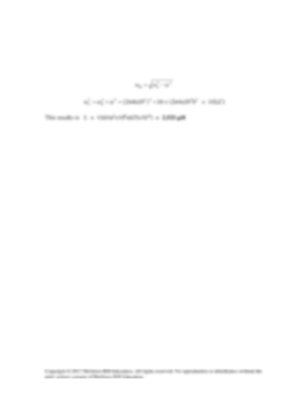
Solution 8.81
t = 1/α = 0.25 leads to α = 4
But, α 1/(2RC) or, C = 1/(2αR) = 1/(2x4x200) = 625 µF
Solution 8.82
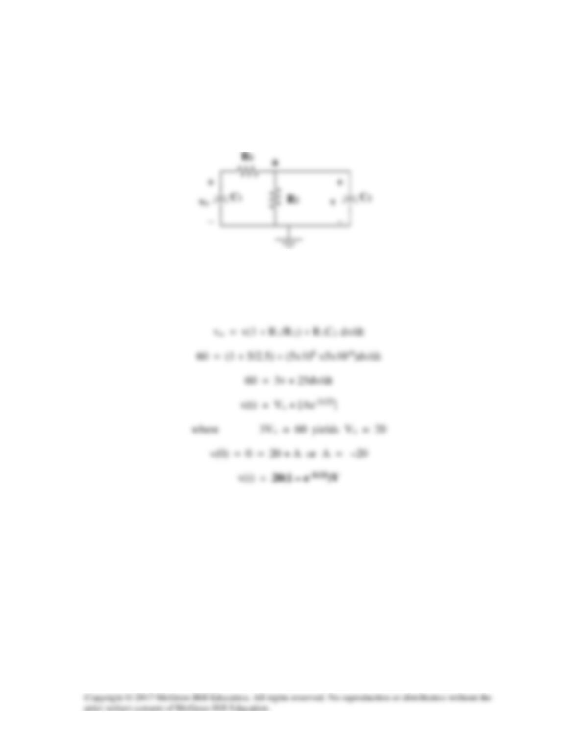
For t = 0-, v(0) = 0.
For t > 0, the circuit is as shown below.
At node a,
(vo – v/R1 = (v/R2) + C2dv/dt

Solution 8.83
i = iD + Cdv/dt (1)
Substituting (1) into (2),
vs = RiD + RCdv/dt + LdiD/dt + LCd2v/dt2 + v = 0