Solution 4.34
Using Fig. 4.102, design a problem that will help other students better understand
Problem
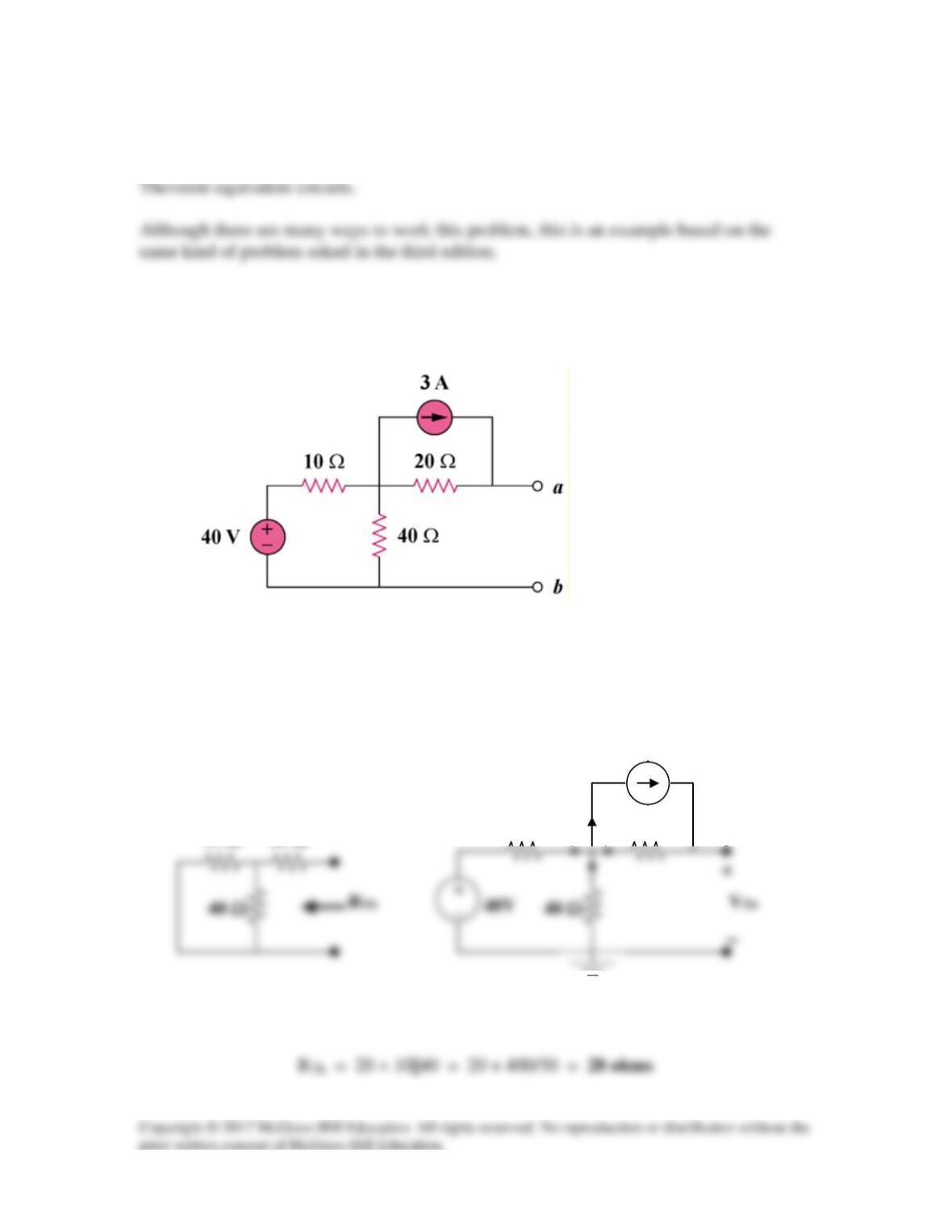
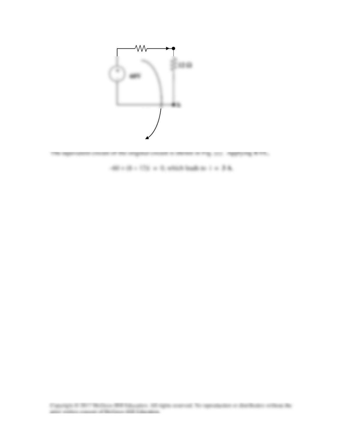
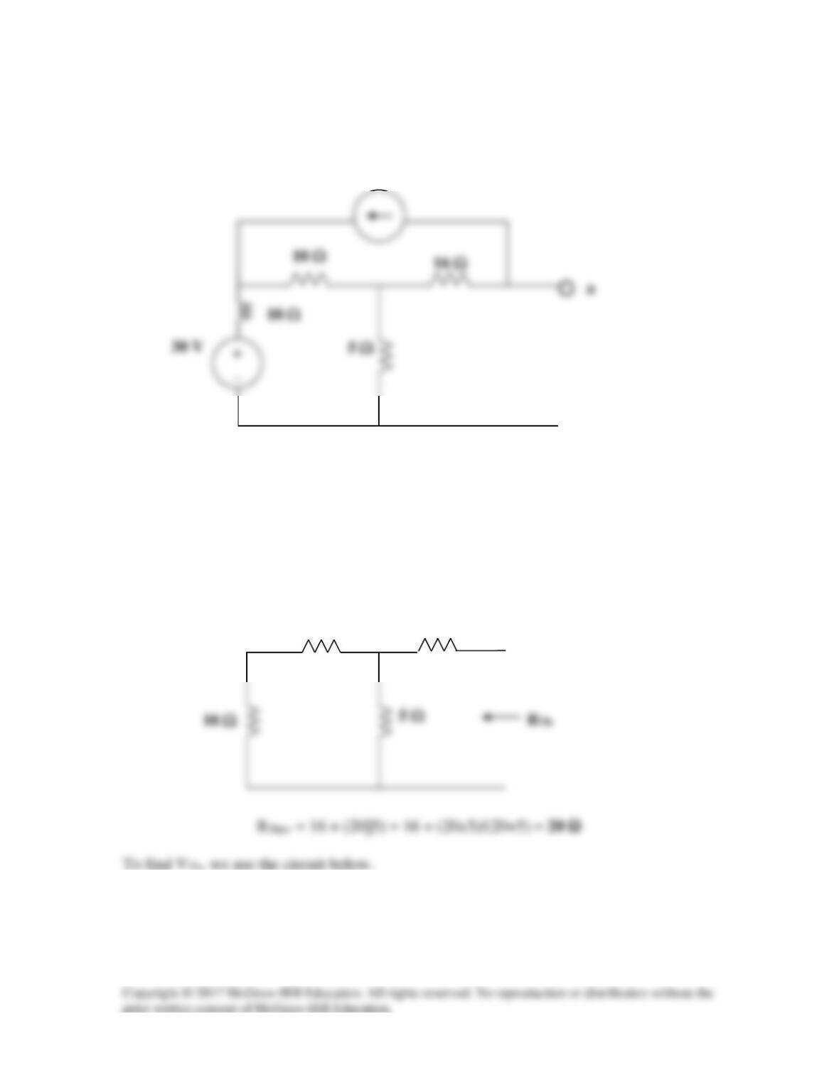
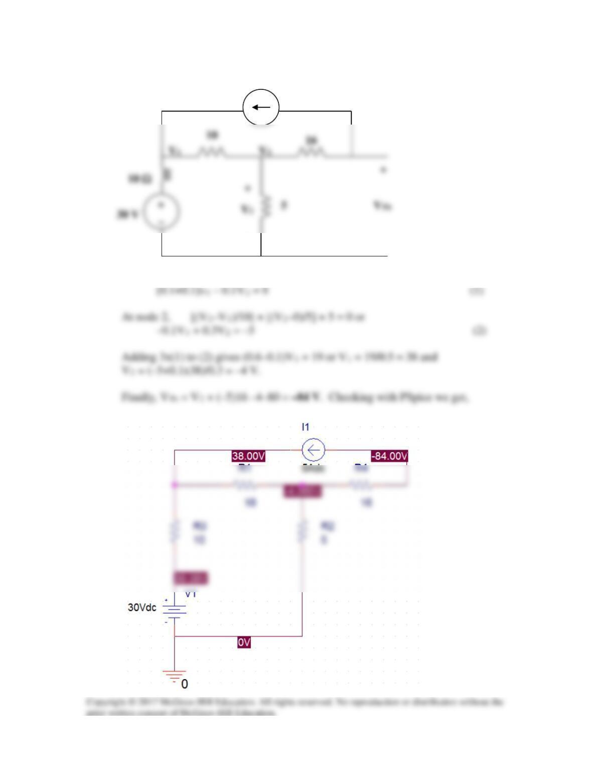
Find the Thevenin equivalent at terminals a–b of the circuit in Fig. 4.102.
Figure 4.102
Solution
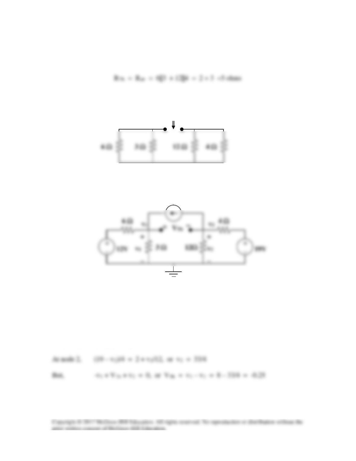
To find RTh, consider the circuit in Fig. (a).
(a)
10 Ω
20 Ω
v1
3 A
10 Ω
20 Ω
v2
(b)

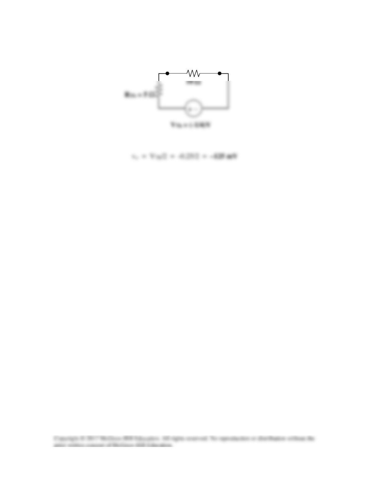
To find VTh , consider the circuit in Fig. (b).
Solution 4.35
To find RTh, consider the circuit in Fig. (a).
To find VTh , consider the circuit shown in Fig. (b).
VTh
At node 1, 2 + (12 – v1)/6 = v1/3, or v1 = 8
(a)
RTh
a
b
(b)
2 A
a
+ −
vo
b
Solution 4.36
Solve for the current i in the circuit of Fig. 4.103 using Thevenin’s theorem. (Hint: Find
the Thevenin equivalent as seen by the 12-Ω resistor.)
Figure 4.103
For Prob. 4.36.
Solution
Although we could just remove the 12 Ω resistor and find the Thevenin equivalent, let us
10Ω
40Ω
a
VTh
40Ω
RTh
+
10Ω
a
i
b
i
(c)
a
8 Ω
Solution 4.37
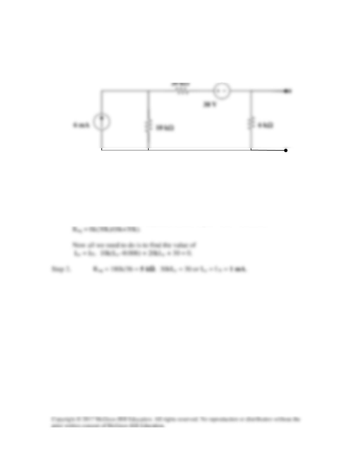
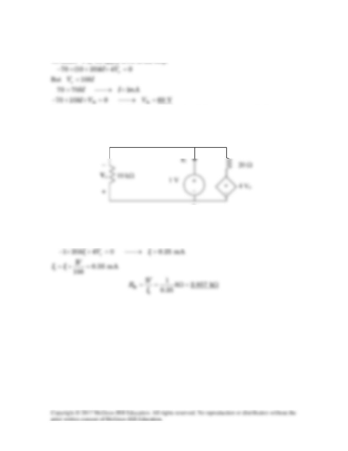
Find the Norton equivalent with respect to terminals a–b in the circuit shown in Fig.
4.104.
a
30 V
6 mA
Figure 4.104
For Prob. 4.37.
Solution
Step 1. Since we do not have a dependent source we can find the equivalent
resistance by setting the independent sources equal to zero. Therefore,
b
Solution 4.38
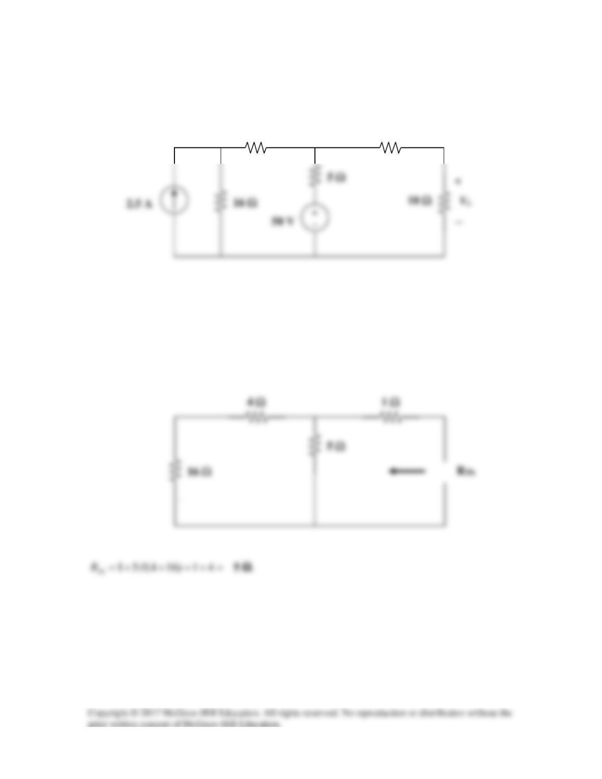
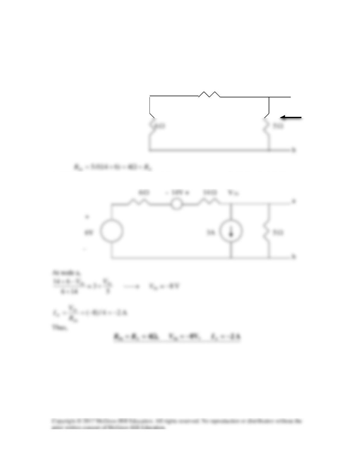
Apply Thevenin’s theorem to find Vo in the circuit of Fig. 4.105.
Figure 4.105
For Prob. 4.38.
Solution
We find Thevenin equivalent at the terminals of the 10-ohm resistor. For RTh , consider
the circuit below.
1 Ω
4 Ω
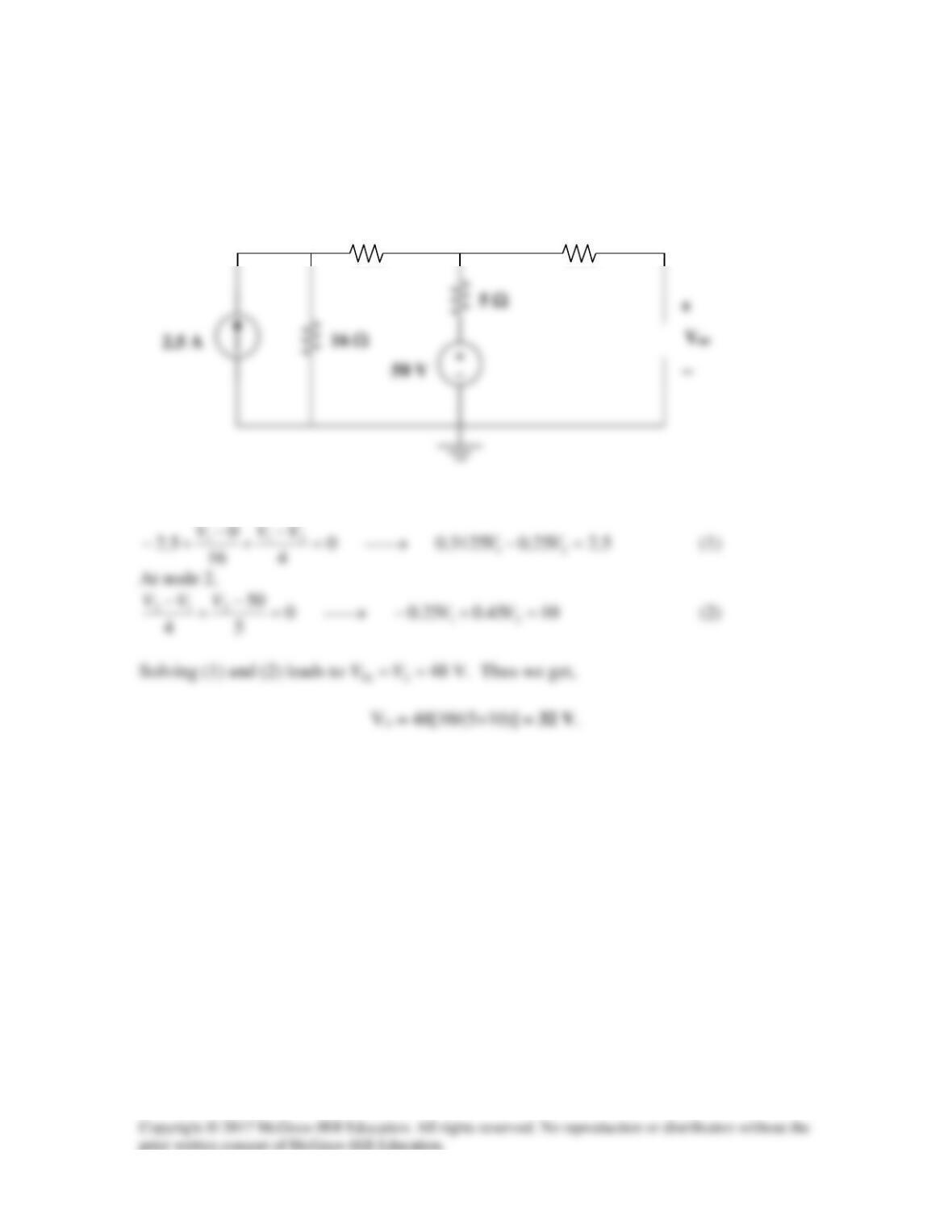
For VTh, consider the circuit below.
At node 1,
1 Ω
4 Ω
V1
V2
Solution 4.39
Obtain the Thevenin equivalent at terminals a-b of the circuit shown in Fig. 4.106.
10 Ω
10 Ω
Figure 4.106
For Prob. 4.39.
Solution
We obtain RTh using the circuit below.
10 Ω
16
5 A
b
+
At node 1, [(V1–30)/10] +[(V1–V2)/10] – 5 = 0 or
5 A
_
_
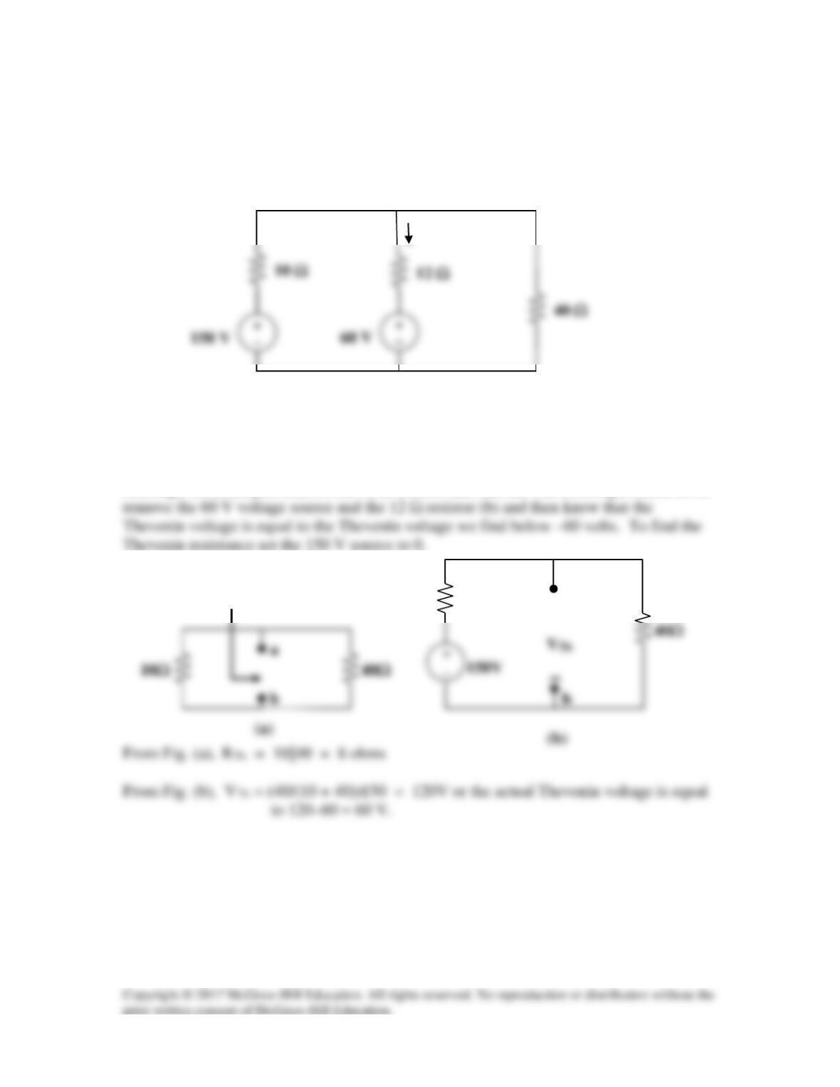
Solution 4.40
To find RTh, we remove the 70-V source and apply a 1-V source at terminals a-b, as
shown in the circuit below.
–
We notice that Vo = -1 V.
b
a
I
1
Solution 4.41
To find RTh, consider the circuit below
14
Ω
a
Ω
Ω
Applying source transformation to the 1-A current source, we obtain the circuit below.
Ω
Ω
Ω
Solution 4.42
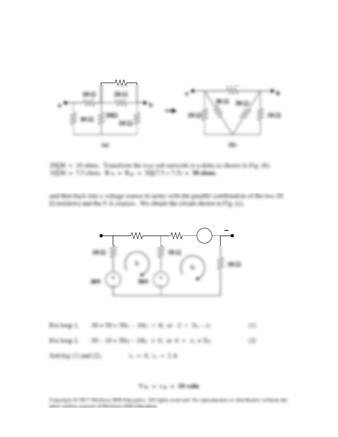
To find RTh, consider the circuit in Fig. (a).
10 Ω
20 Ω
To find VTh , we transform the 20-V (to a current source in parallel with the 20 Ω resistor
Applying KVL to the output loop, -vab – 10i1 + 30 – 10i2 = 0, vab = 10 V
30 Ω
20 Ω
10 Ω
− +
10 V
a
b
+
10 Ω
(c)
Solution 4.43
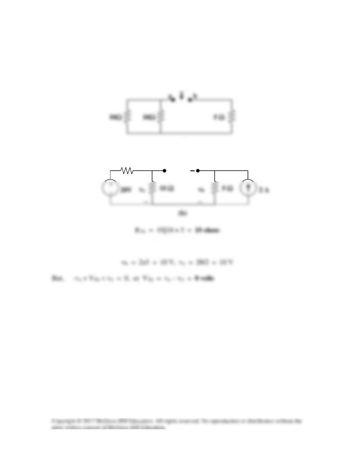
To find RTh, consider the circuit in Fig. (a).
a
b
(b)
To find VTh , consider the circuit in Fig. (b).
(a)
RTh
10 Ω
VTh
+
+
+
b
a
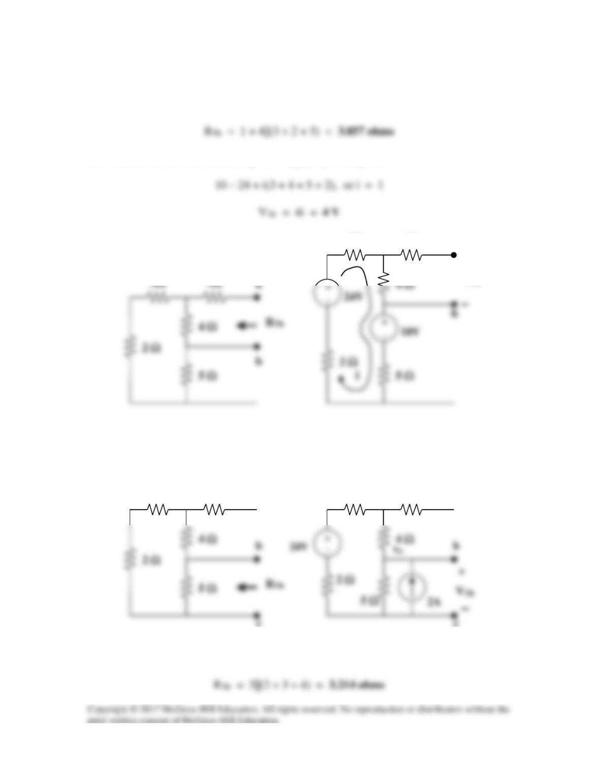
Solution 4.44
(a) For RTh, consider the circuit in Fig. (a).
For VTh, consider the circuit in Fig. (b). Applying KVL gives,
a
1Ω
3Ω
(b) For RTh, consider the circuit in Fig. (c).
VTh
+
(b)
VTh
+
1Ω
3Ω
a
(a)
c
(c)
1Ω
3Ω
(d)
1Ω
3Ω
c

To get VTh, consider the circuit in Fig. (d). At the node, KCL gives,
Solution 4.45
Find the Thevenin equivalent of the circuit in Fig. 4.112 as seen by looking into terminals
a and b.
Figure 4.112
For Prob. 4.45.
Solution
For Req, consider the circuit in Fig. (a).
(b)
(a)
Solution 4.46
Using Fig. 4.113, design a problem to help other students better understand Norton
Problem
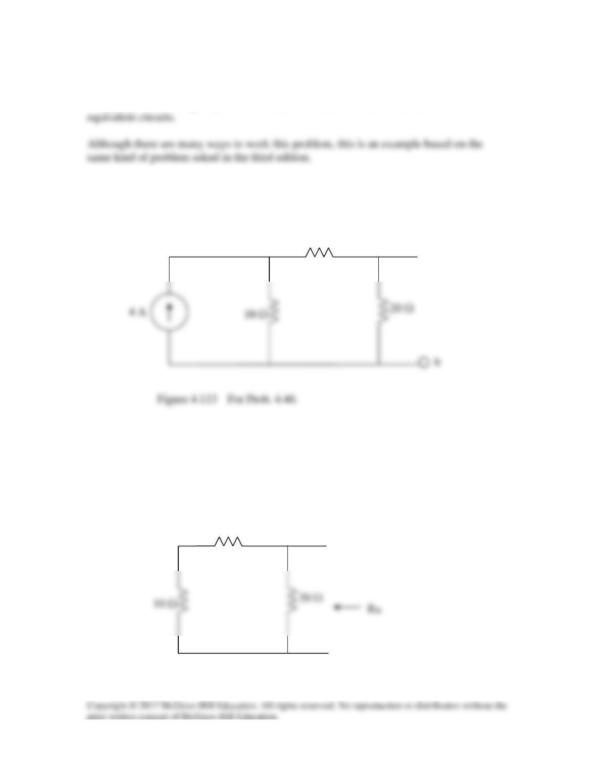
Find the Norton equivalent at terminals a-b of the circuit in Fig. 4.113.
10 Ω
20 Ω
b
Solution
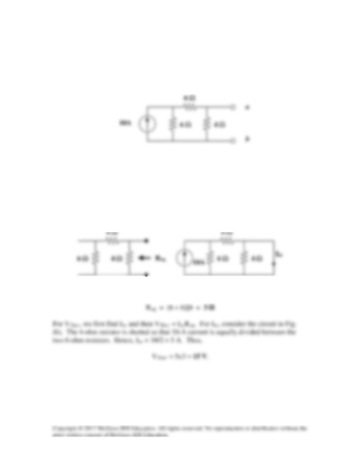
RN is found using the circuit below.
10 Ω
10 Ω
a
b
10 Ω
a
RN = 20//(10+10) = 10 Ω
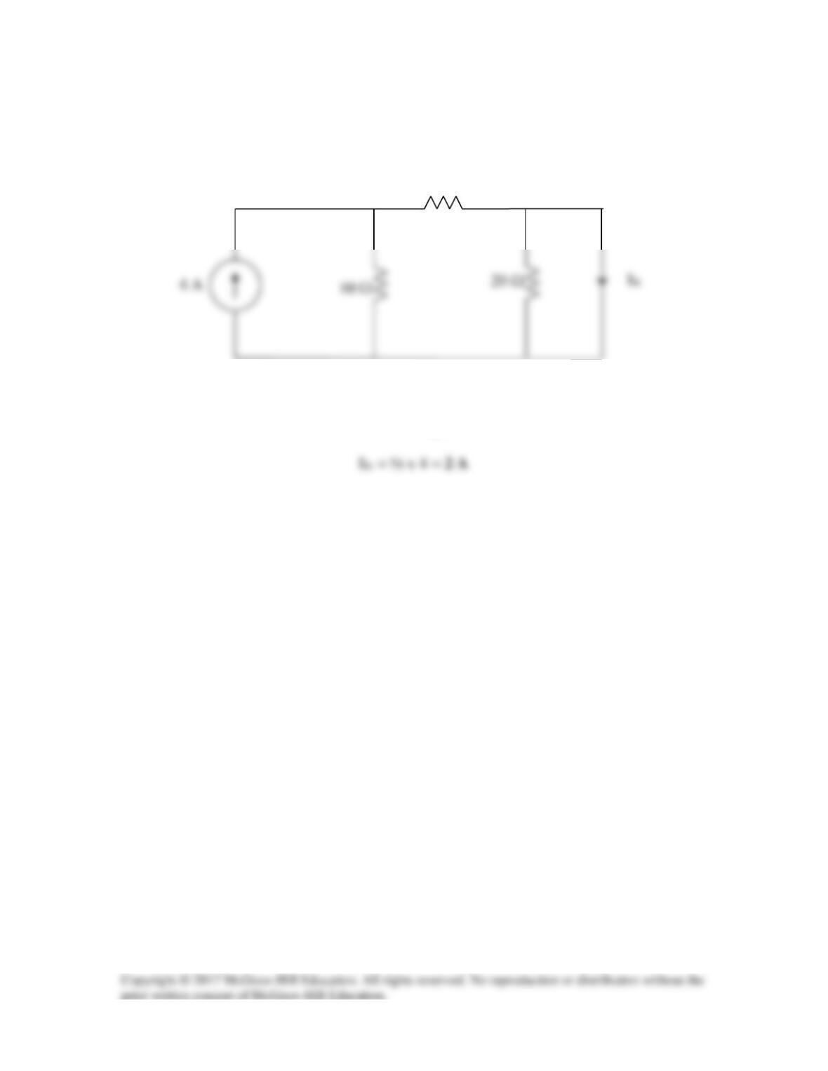
To find IN, consider the circuit below.
10 Ω
20 Ω
The 20-Ω resistor is short-circuited and can be ignored.
10 Ω