Solution 13.1
For coil 1, L1 – M12 + M13 = 12 – 8 + 4 = 8
Solution 13.2
Using Fig. 13.73, design a problem to help other students to better understand mutual
inductance.
Although there are many ways to solve this problem, this is an example based on the
same kind of problem asked in the third edition.
Problem
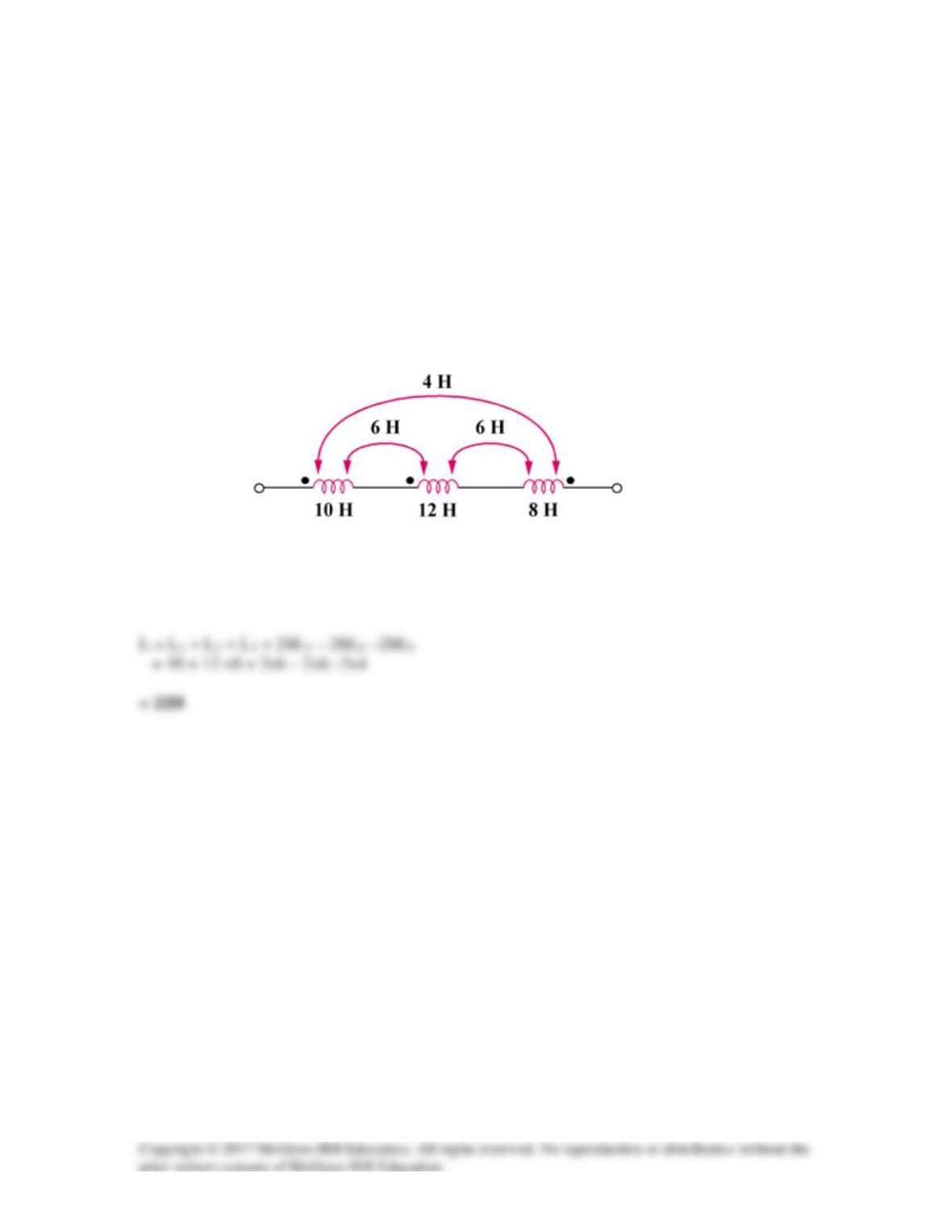
Determine the inductance of the three series-connected inductors of Fig. 13.73.
Figure 13.73
Solution
Solution 13.3
L1 + L2 + 2M = 500 mH (1)
Solution 13.4
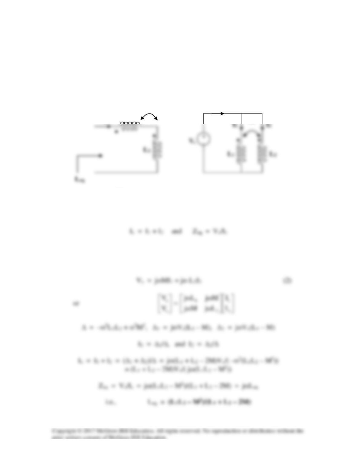
(a) For the series connection shown in Figure (a), the current I enters each coil from
its dotted terminal. Therefore, the mutually induced voltages have the same sign as the
self-induced voltages. Thus,
Leq = L1 + L2 + 2M
I2
I1
(b) For the parallel coil, consider Figure (b).
Applying KVL to each branch gives,
Vs = jωL1I1 + jωMI2 (1)
M
(a)
(b)
M
I
Is
L
1
Solution 13.5
(a) If the coils are connected in series,
(b) If they are connected in parallel,
Problem 13.6
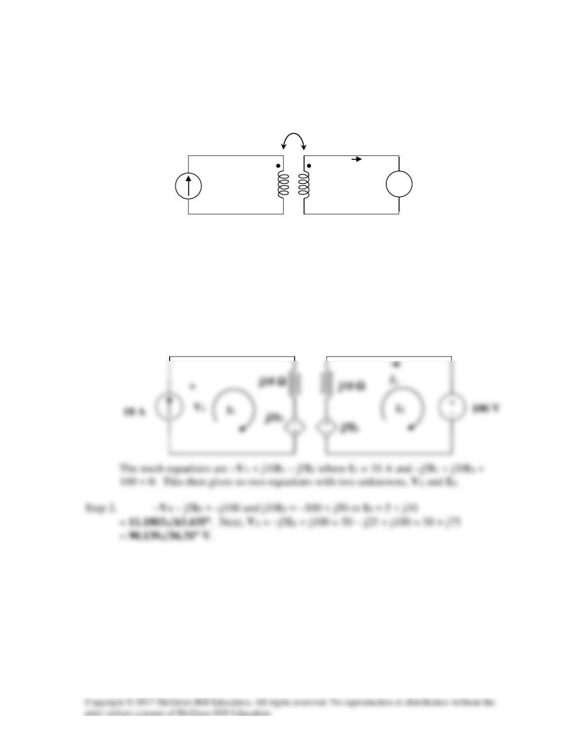
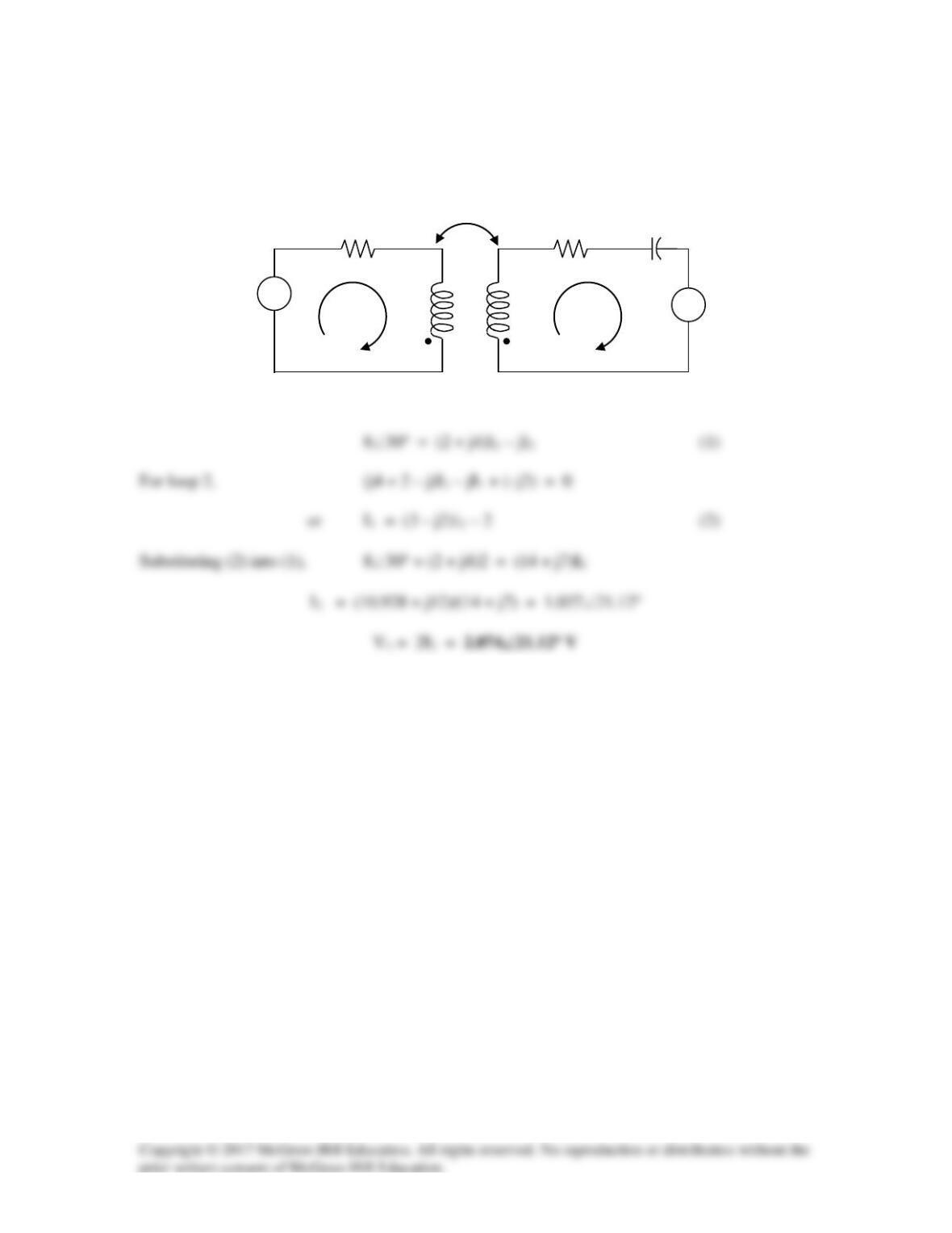
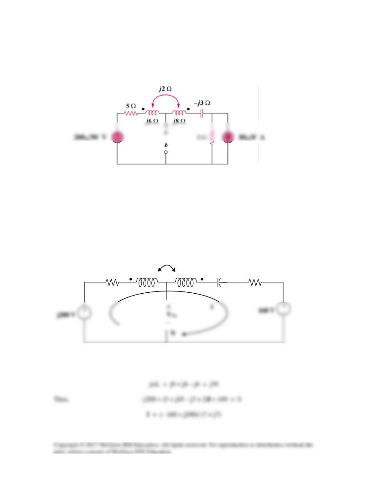
Given the circuit shown in Fig. 13.75. Determine the value of V1 and I2.
Figure 13.75
For Prob. 13.6.
Solution
Step 1. First we need to replace the coupled inductors with the dependent source
model. Next we need to determine the signs on the dependent sources using the
dot convention. Now we can write mesh equations around each loop and solve
for I2 and I1. Once we have I1 and I2 we can find V1.
−
100∠0° V
+
−
10∠0° A
j5 Ω
j10 Ω
j10 Ω
I2
+
V1
−
Solution 13.7
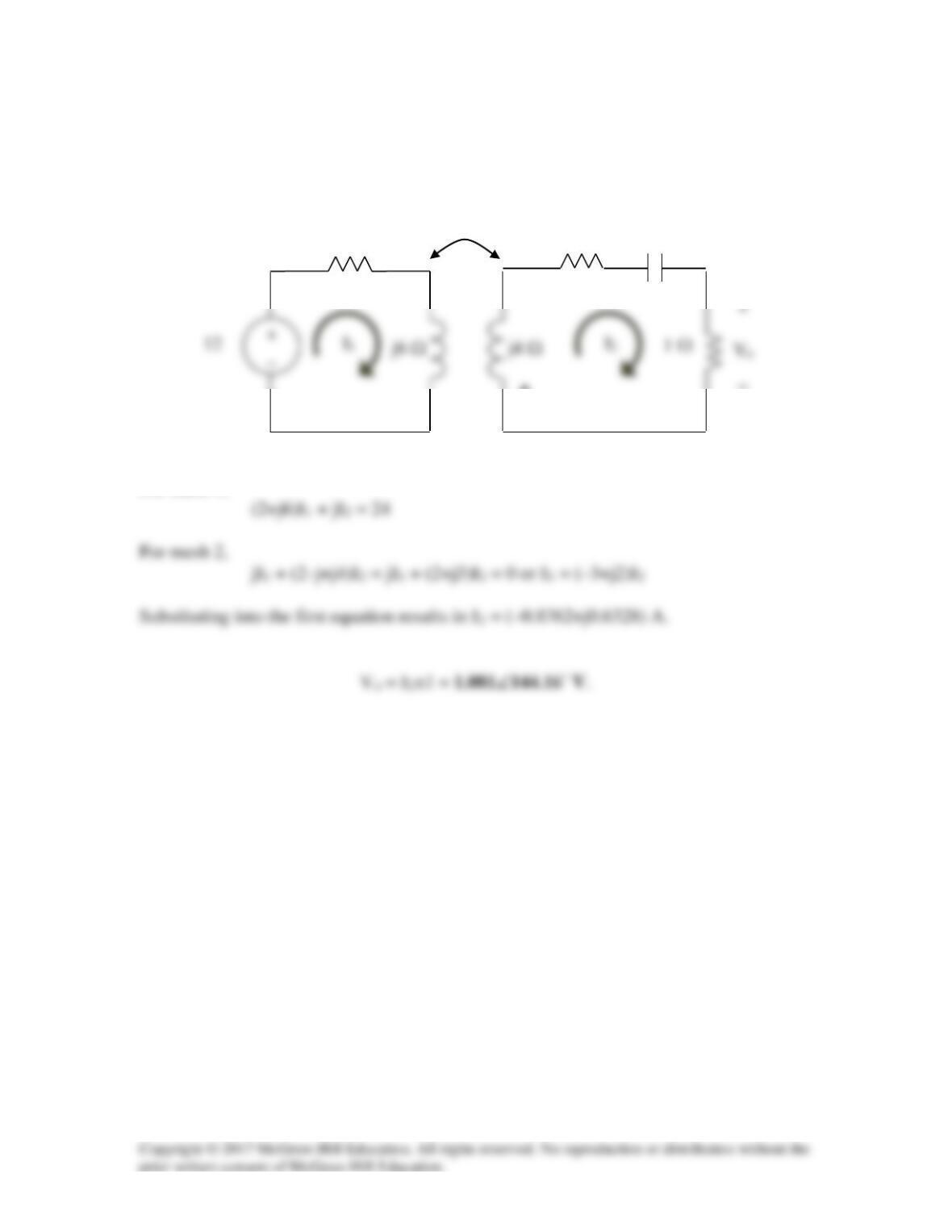
We apply mesh analysis to the circuit as shown below.
j6 Ω
j4 Ω
For mesh 1,
2 Ω
•
•
1 Ω
–j1 Ω
j1 Ω
Solution 13.8
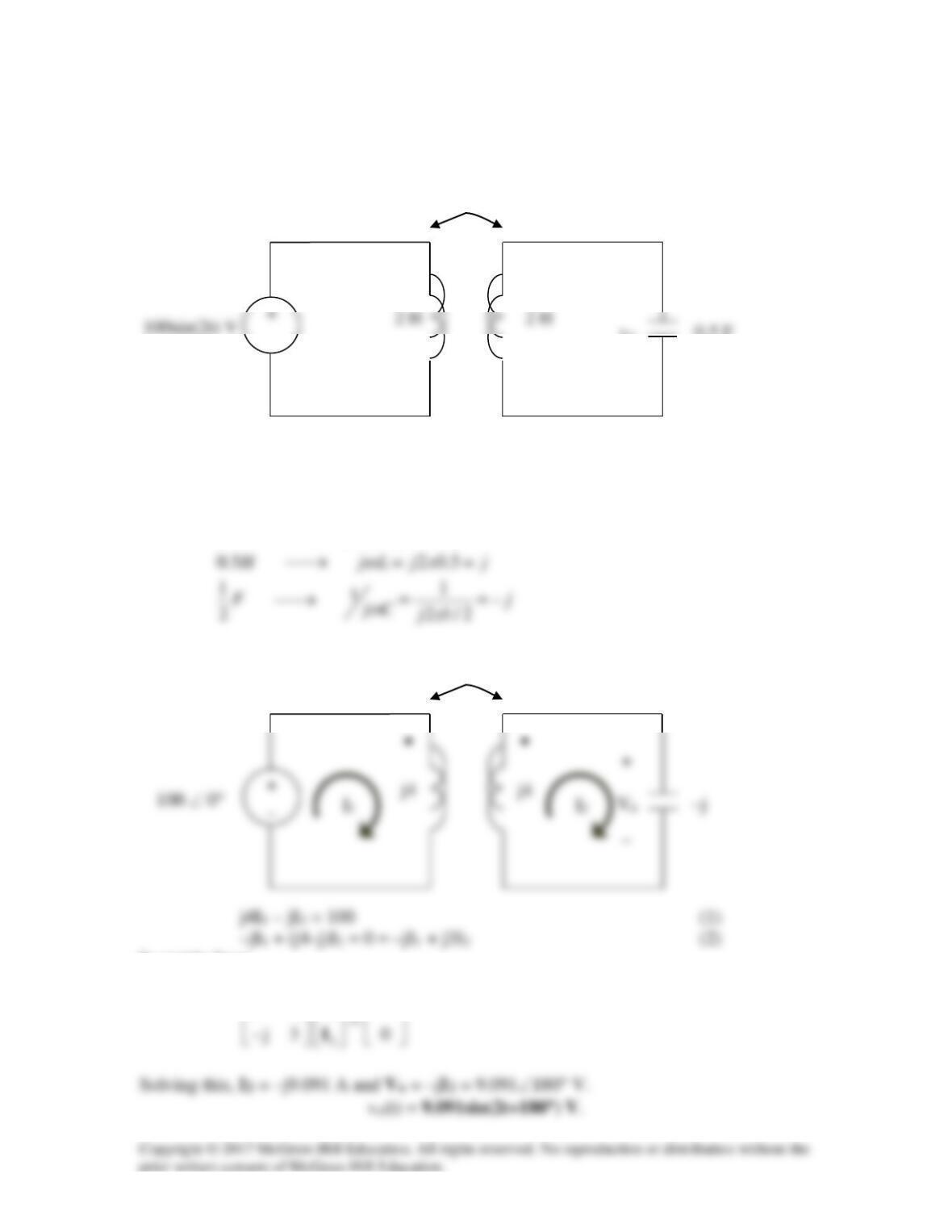
Find v(t) for the circuit in Fig. 13.77.
Figure 13.77
For Prob. 13.8.
Solution
Step 1. We need to transform the circuit into the frequency domain and replace
the coupled inductors with the dependent source model. In addition, we need to replace
the current source in parallel with the resistor with the equivalent voltage source in series
with the resistor (source transformation).
Step 2. From the first loop equation we get (20+j20)I1 = j10I2 or I1 = (0.25+j0.25)I2.
5 H
−
+
10 Ω
10 Ω
20 Ω
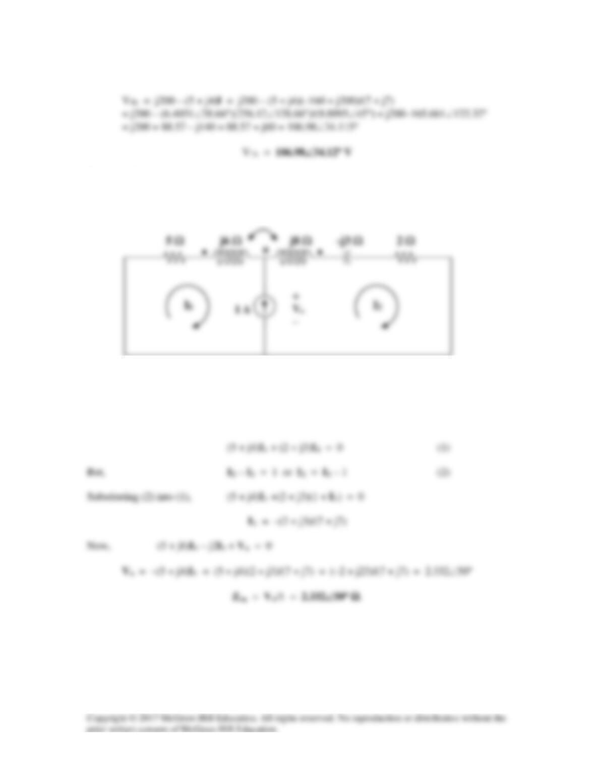
Solution 13.9
Consider the circuit below.
For loop 1,
2 Ω
I1
I2
+
–
8∠30
o
2 Ω
j 4
j 4
–j1
+
–
–j2V
j1
Solution 13.10
Find vo(t) in the circuit in Fig. 13.79.
Figure 13.79
For Prob. 13.10.
Solution
2 22 4H jL jx j
ω
→ = =
Consider the circuit below.
In matrix form,
1
j4 j 100
−
I
j
_
•
•
+
_
v
o
0.5 H
0.5 F
Solution 13.11
3
−
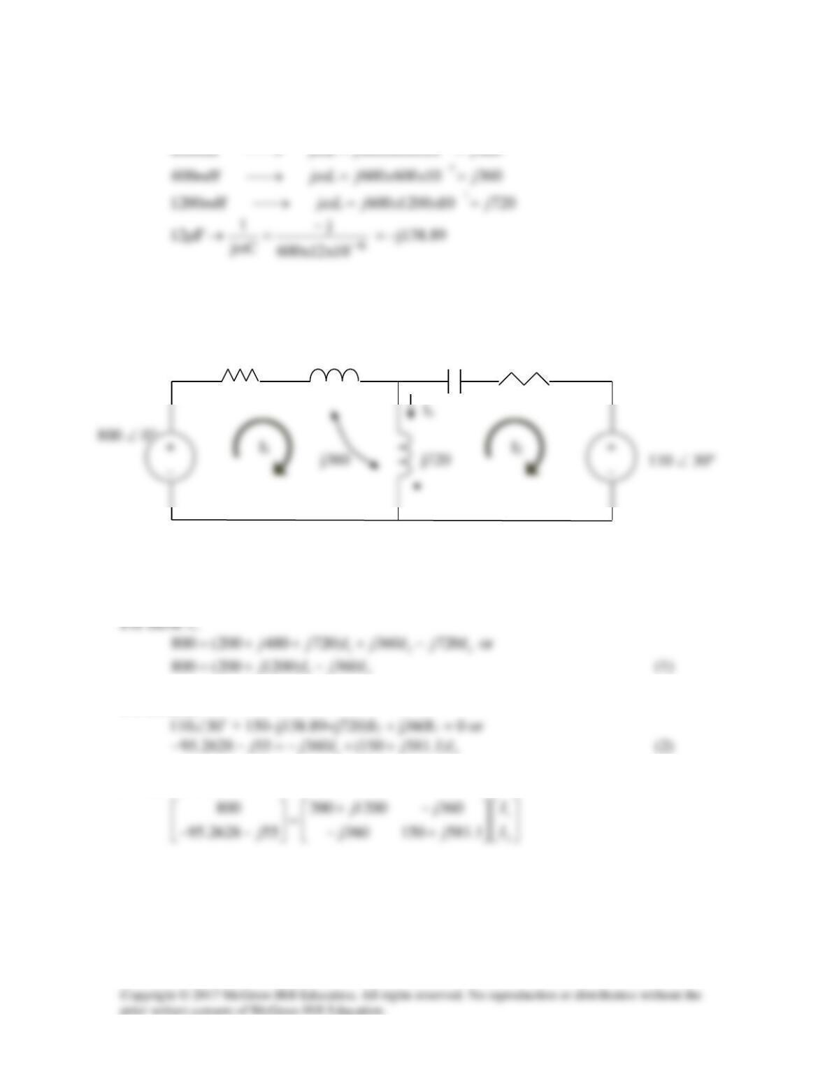
After transforming the current source to a voltage source, we get the circuit shown below.
12
For mesh 2,
12
In matrix form,
-j138.89
200
•
j480
150

Solving this using MATLAB leads to:
>> Z = [(200+1200i),-360i;-360i,(150+581.1i)]
Z =
Solution 13.12
Let
.1=
ω
j8
j4
Applying KVL to the loops,
21
Solving (1) and (2) gives I1 = –j0.0703. Thus

Solution 13.13
An alternate approach would be to use the equation,
Zin
++=
++= 31.562111.7
4
5j4
4
)5(j4
I1
I2
j2I2
j5
+
–
j5
–
+
j2I1
+
_
80 ∠ 0°
j2 Ω
4 Ω
4 Ω
–j Ω
Solution 13.14
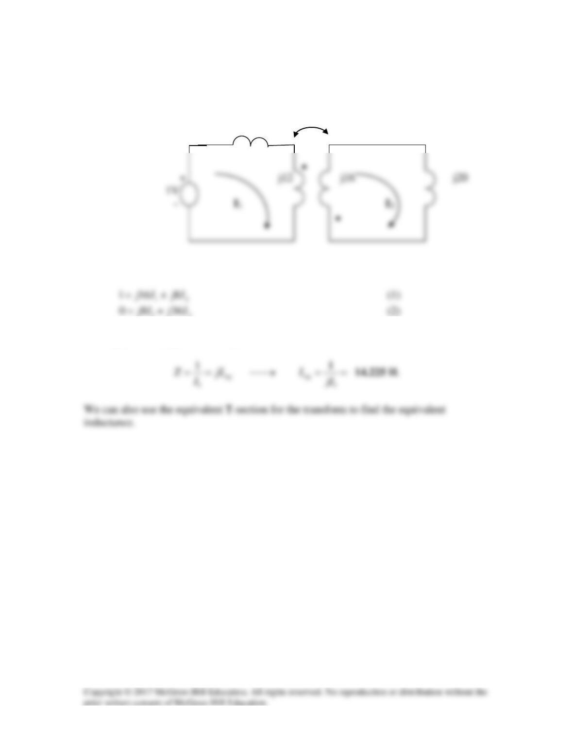
Obtain the Thevenin equivalent circuit for the circuit in Fig. 13.83 at terminals
a–b.
Figure 13.83
For Prob. 13.14.
Solution
To obtain VTh, convert the current source to a voltage source as shown below.
Note that the two coils are connected series aiding.
ωL = ωL1 + ωL2 – 2ωM
2 Ω
j2
a
–j3 Ω
j8 Ω
j6 Ω
5 Ω
But, –j200 + (5 + j6)I – j2I + VTh = 0
To obtain ZTh, we set all the sources to zero and insert a 1–A current source at the terminals
a–b as shown below.
Clearly, we now have only a super mesh to analyze.
(5 + j6)I1 – j2I2 + (2 + j8 – j3)I2 – j2I1 = 0
j2
b
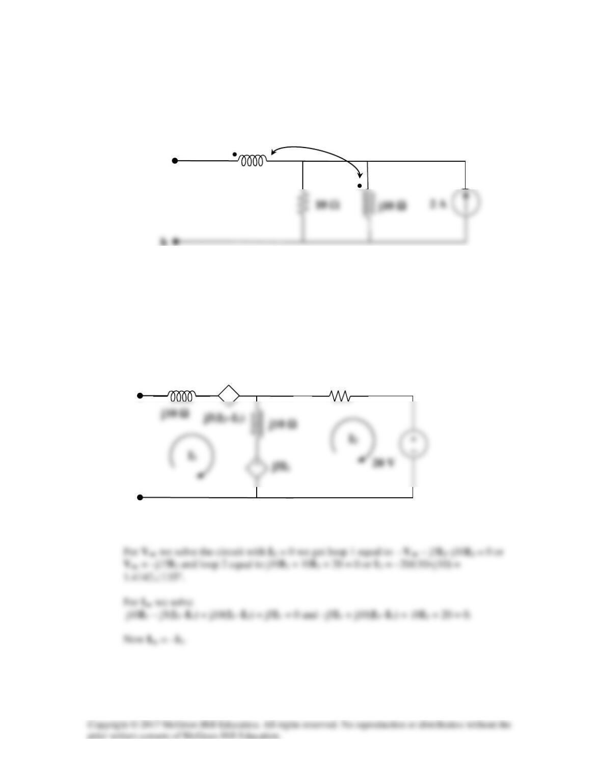
Solution 13.15
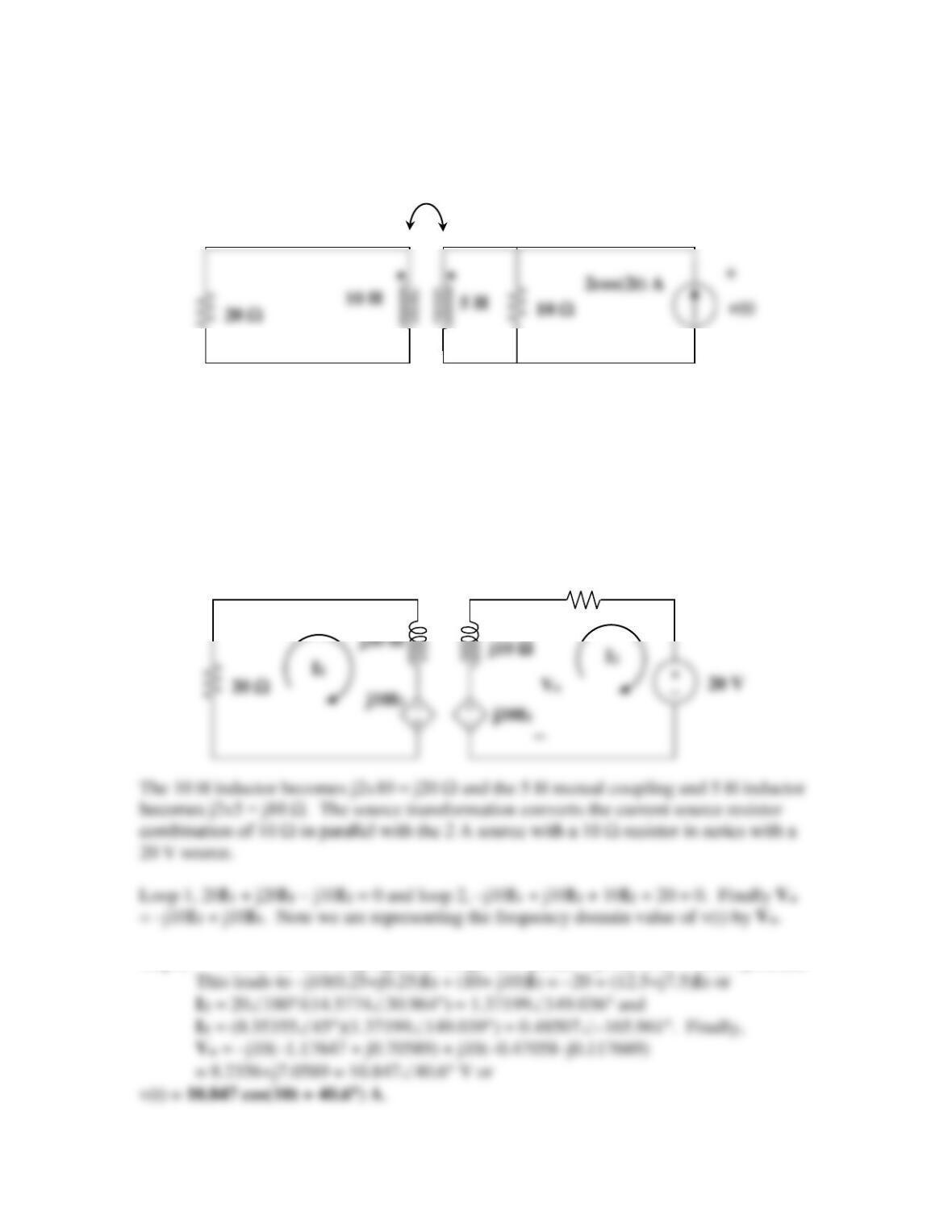
Find the Norton equivalent for the circuit in Fig. 13.84 at terminals a–b.
j10 Ω
Figure 13.84
For Prob. 13.15.
Solution
Step 1. Since the current source is actually in parallel with the 10 Ω resistor, we can use
source transformation to convert them into a resistance of 10Ω in series with a 20 V
source. We next replace the mutually coupled inductors with their dependent source
equivalent and establish the unknown loop currents. We use the dot convention to
determine the signs on the dependent sources.
Clearly we need to find Voc and Isc since we have dependent sources. Thus, we have two
circuits one with an open circuit at ab and the next is the short circuit at terminals ab.
b
a
j5 Ω
j10 Ω
10 Ω
− +

Step 2. Voc = –j15(1.4142∠135°) = 21.213∠45° V.
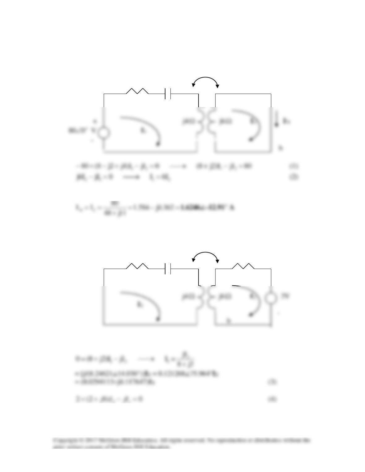
Solution 13.16
To find IN, we short-circuit a-b.
j
Ω
8
Ω
–j2
Ω
a
Ω
Ω
Solving (1) and (2) leads to
To find ZN, insert a 1–A current source at terminals a-b. Transforming the current source
to voltage source gives the circuit below.
j
Ω
8
Ω
–j2
Ω
2
Ω
a
••
+
Ω
Ω
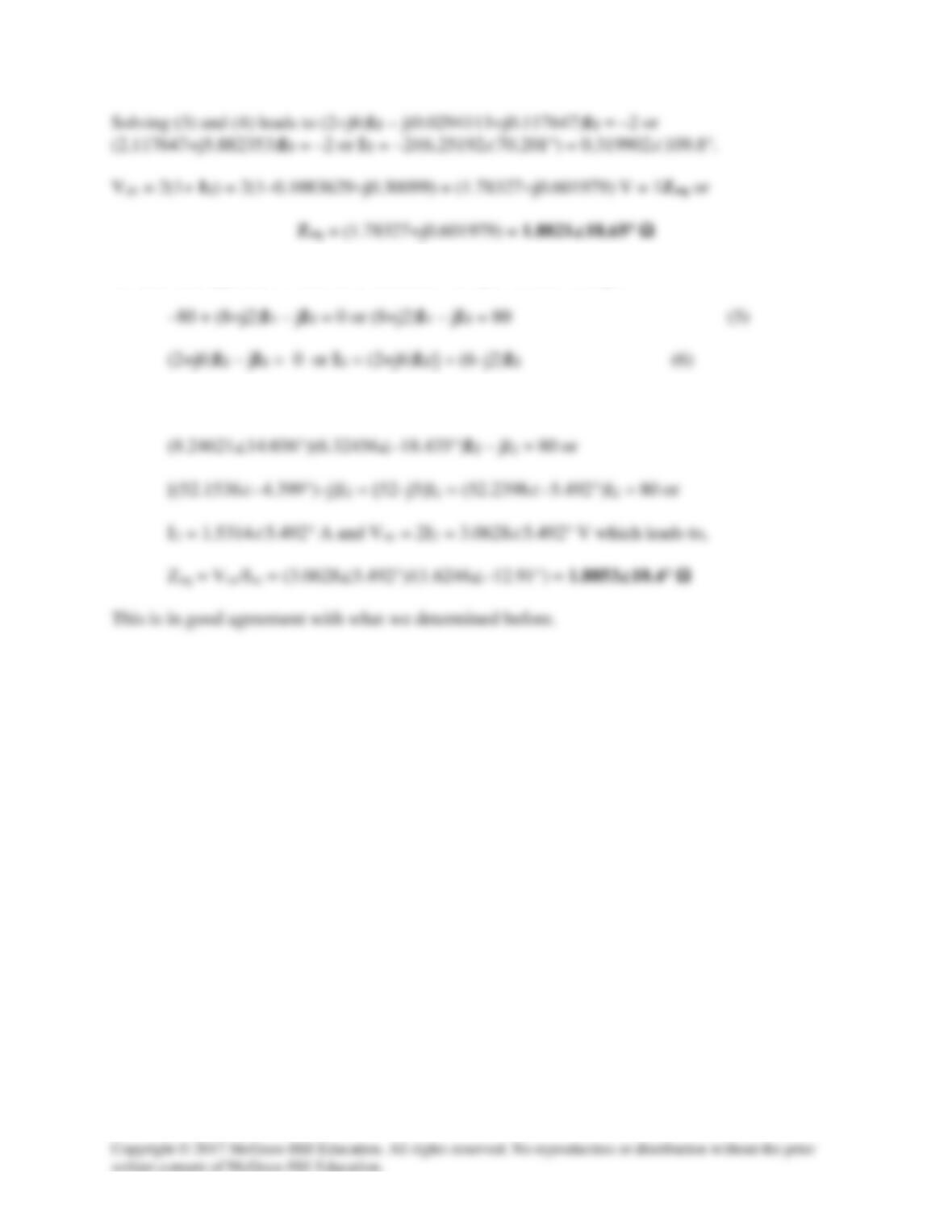
An alternate approach would be to calculate the open circuit voltage.
Substituting (6) into (5) we get,