1 Ω
2 Ω
Solution 19.38
From eq. (19.75),
Solution 19.39
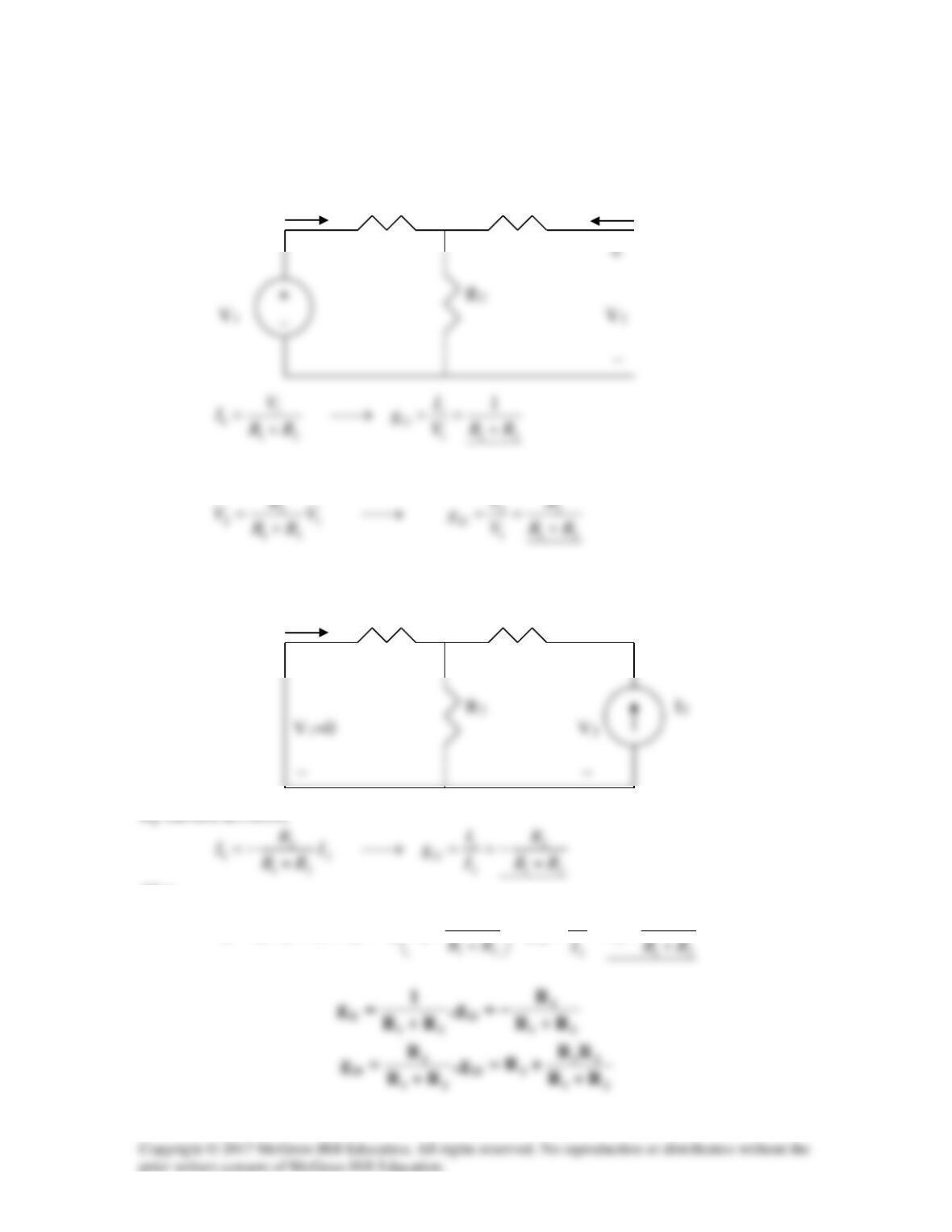
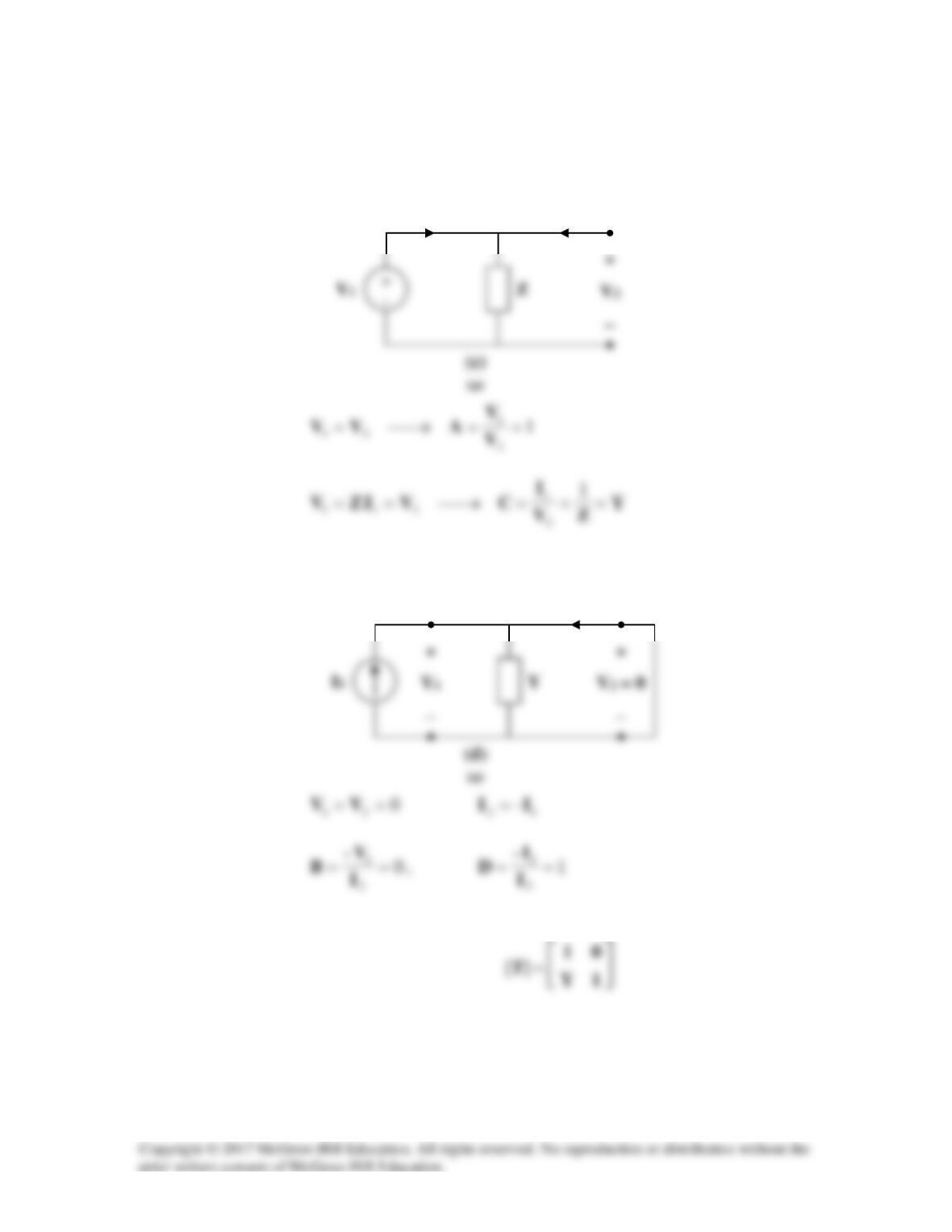
We obtain g11 and g21 using the circuit below.
I1 R1 R3 I2=0
By voltage division,
We obtain g12 and g22 using the circuit below.
I1 R1 R3
+ +
By current division,
Also,
12
2 23 1 2 2 3
( // ) RR
V IR R R I R RR
=+=+
2 12
22 3
V RR
gR
= = + +
Solution 19.40
Using Fig. 19.97, design a problem to help other students to better understand how to find
g parameters in an ac circuit.
Although there are many ways to solve this problem, this is an example based on the
same kind of problem asked in the third edition.
Problem
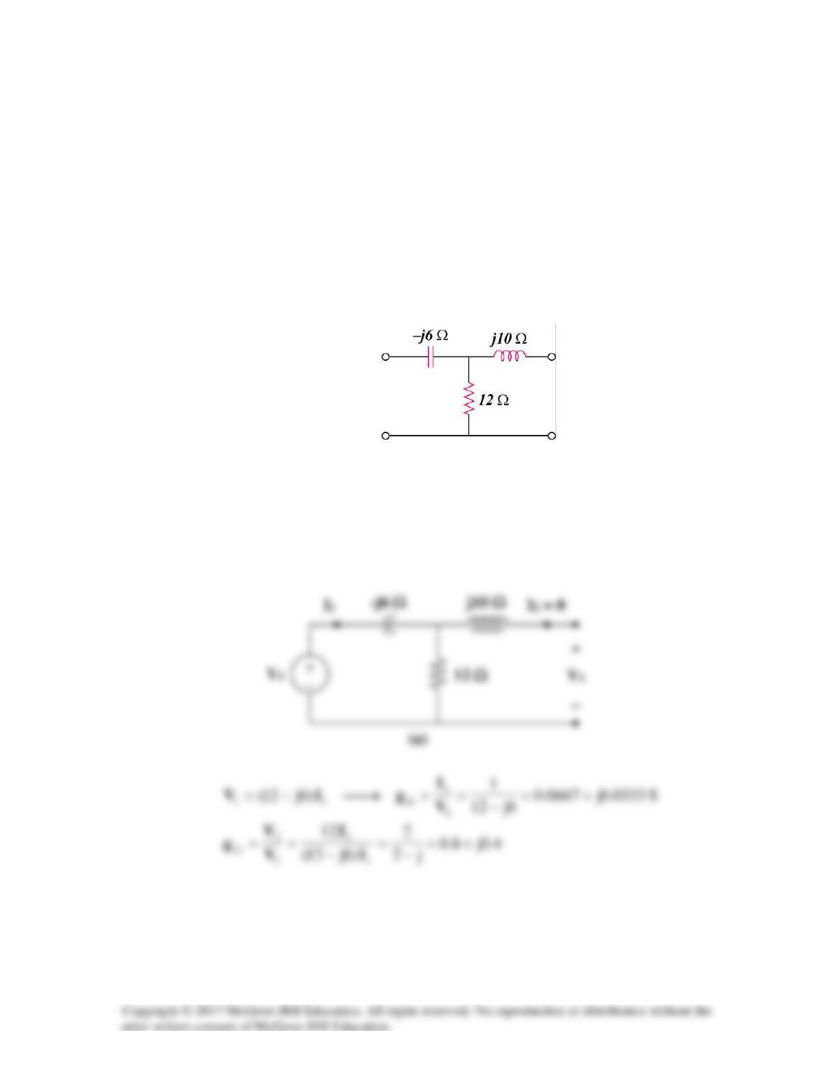
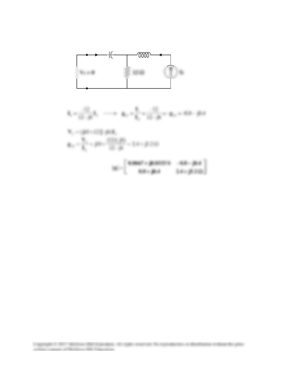
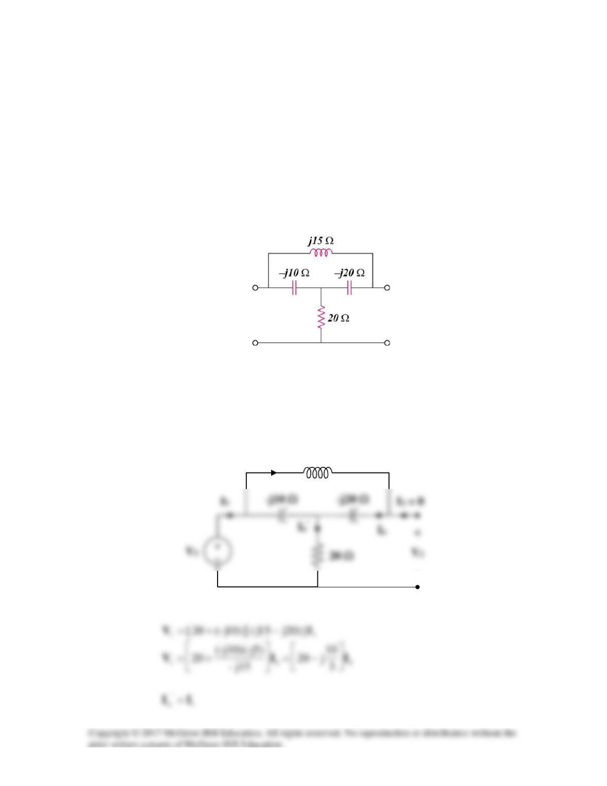
Find the g parameters for the circuit in Fig.19.97.
Figure 19.97
Solution
To get
11
g
and
21
g
, consider the circuit in Fig. (a).
To get
12
g
and
22
g
, consider the circuit in Fig. (b).
(b)
I2
+
−
j10 Ω
–j6 Ω
I1
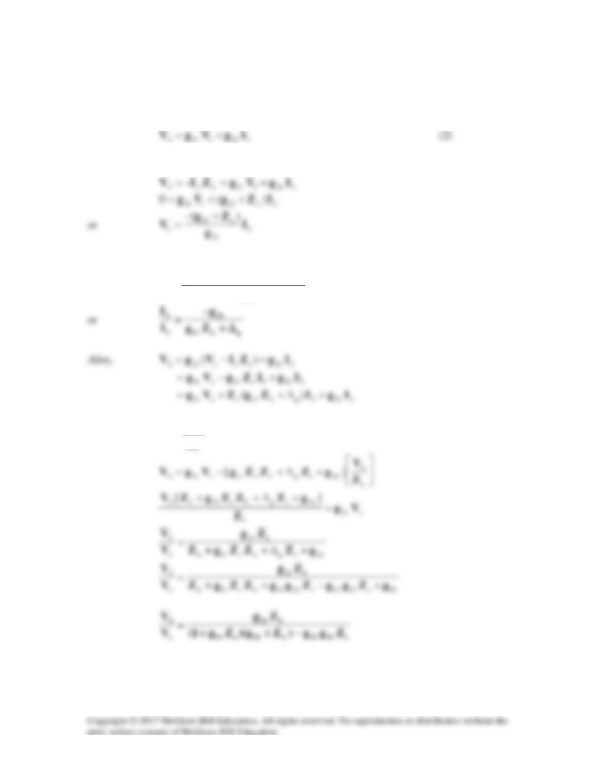
Solution 19.41
For the g parameters
2121111 IgVgI +=
(1)
But
s1s1 ZIVV −=
and
Substituting this into (1),
2
21
122111L1122
1
–
)( I
g
gggZgg
I−+
=
But
2
2
–
Z
V
I=
Solution 19.42
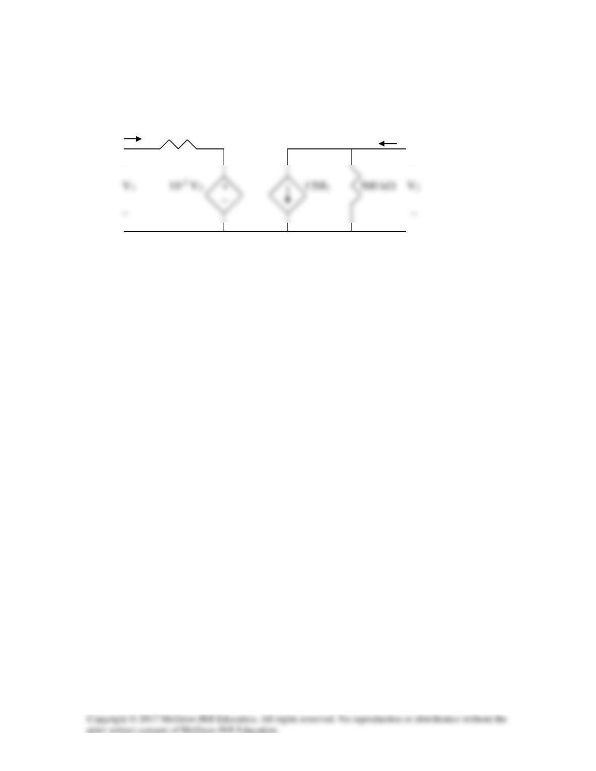
With the help of Fig. 19.20, we obtain the circuit model below.
I1 600 Ω I2
+ +
Solution 19.43
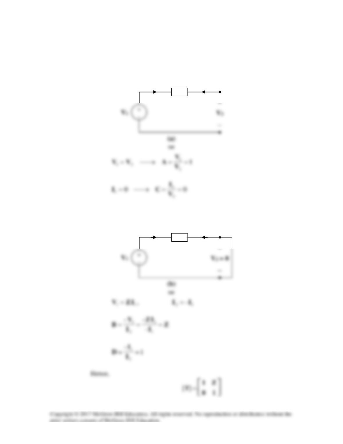
(a) To find
A
and
C
, consider the network in Fig. (a).
To get
B
and
D
, consider the circuit in Fig. (b).
Z
I1
I2
Z
I1
I2
(b) To find
A
and
C
, consider the circuit in Fig. (c).
To get
B
and
D
, refer to the circuit in Fig.(d).
Thus,
I1
I2
I2
Solution 19.44
Using Fig. 19.99, design a problem to help other students to better understand how to find
the transmission parameters of an ac circuit.
Although there are many ways to solve this problem, this is an example based on the
same kind of problem asked in the third edition.
Problem
Determine the transmission parameters of the circuit in Fig.19.99.
Figure 19.99
Solution
To determine
A
and
C
, consider the circuit in Fig.(a).
j15 Ω
I1
Io
(a)
(a)
−
Io
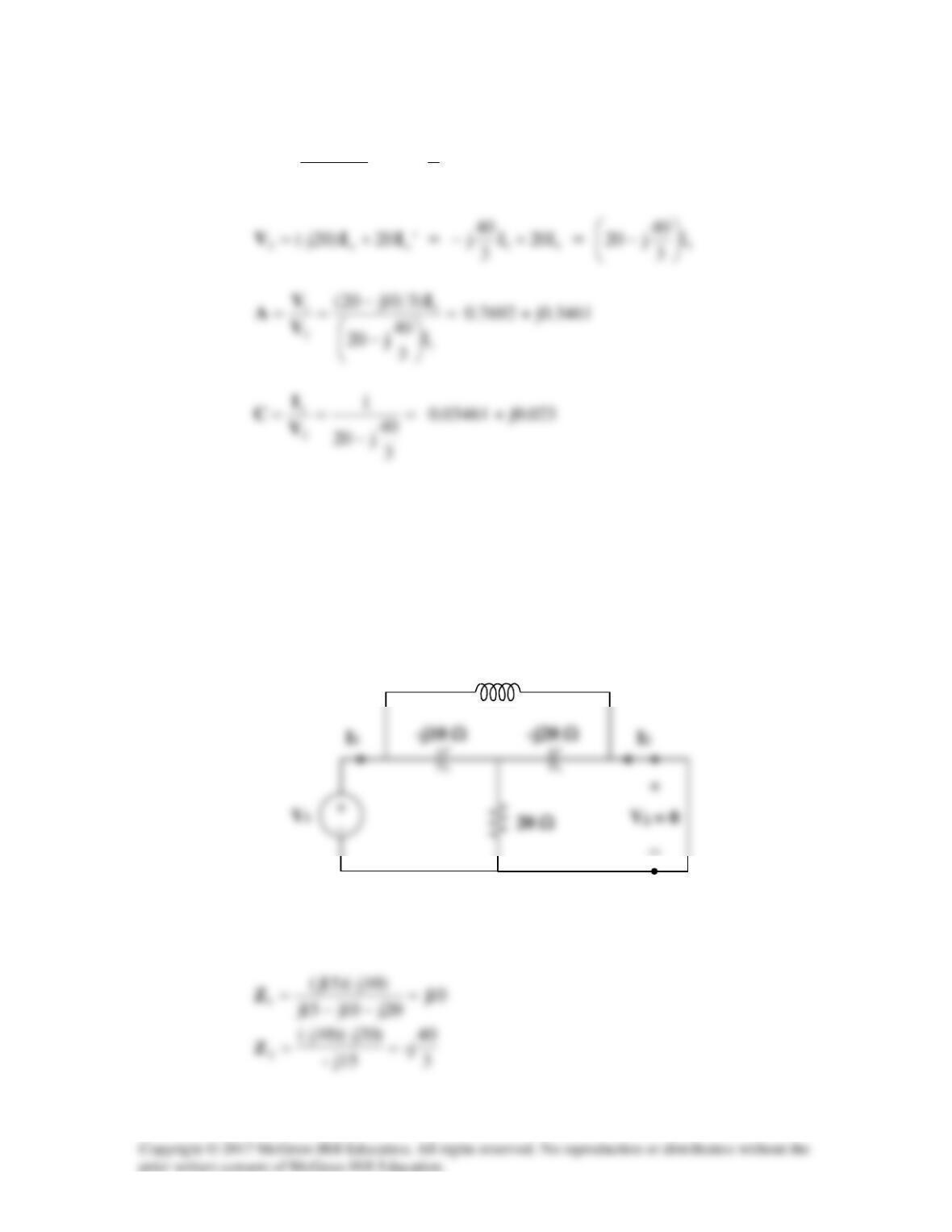
11o 3
2
5j10j–
10j– III
=
−
=
To find
B
and
D
, consider the circuit in Fig. (b).
We may transform the ∆ subnetwork to a T as shown in Fig. (c).
j15 Ω
(b)
(a)
−
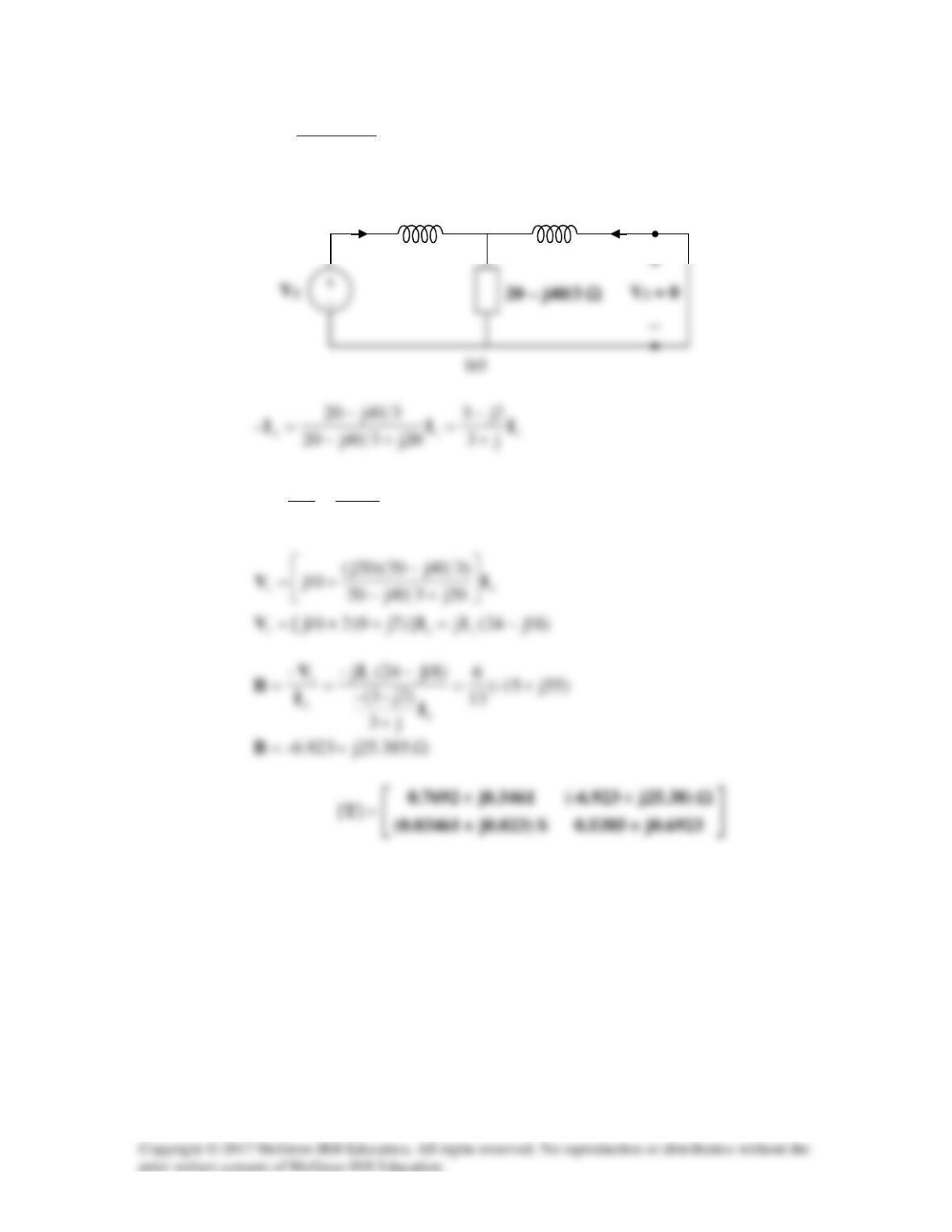
20j
j15–
-j20))(15j(
3==Z
6923.0j5385.0
2j3
j3
–
2
1
+=
−
+
== I
I
D
j10 Ω
I1
I2
j20 Ω
Solution 19.45
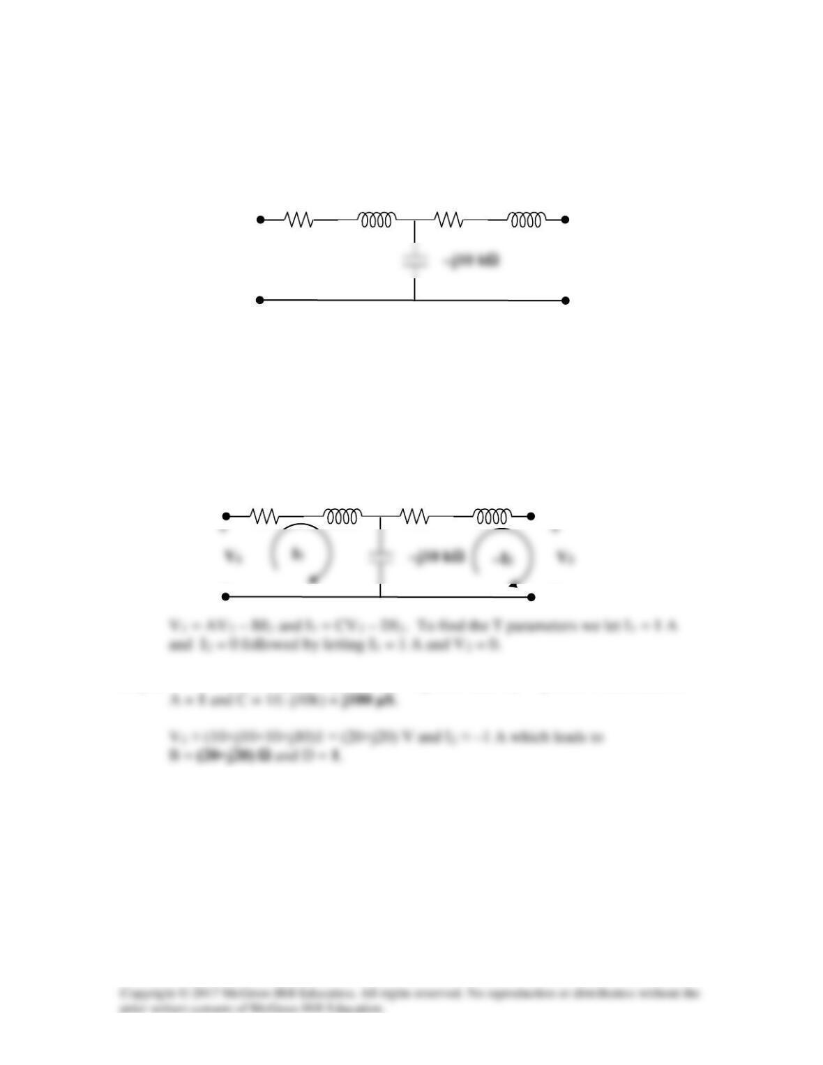
Find the ABCD parameters for the circuit in Fig. 19.100.
Figure 19.100
For Prob. 19.45.
Solution
Step 1. First we need to label all of the currents and voltages so we can apply the
defining equations for the T parameters.
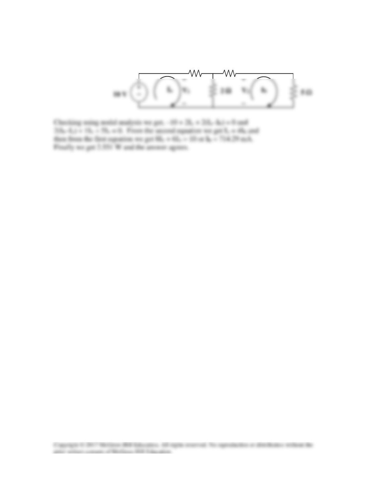
Step 2. V1 = (10+j10)1 – j10,000×1 ≈ –j10 kV and V2 = –j10 kV which leads to
j10 Ω
10 Ω
j10 Ω
10 Ω
j10
Ω
10 Ω
j10
Ω
10 Ω
−
−
Solution 19.46
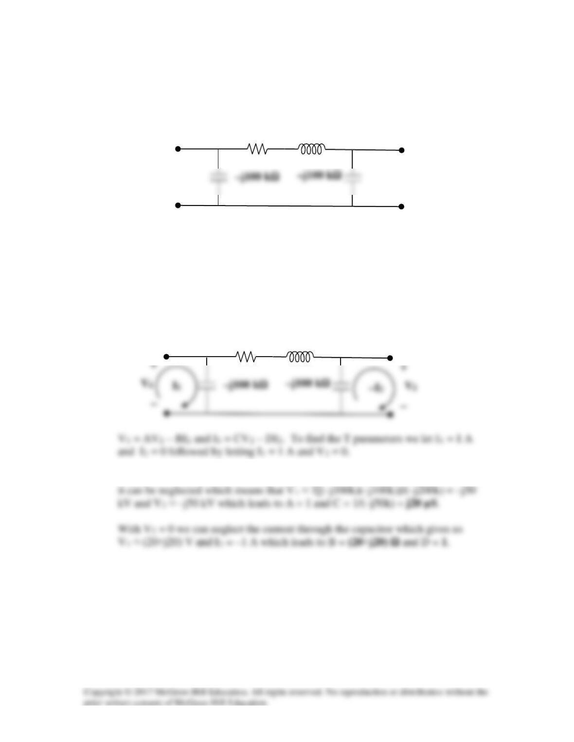
Find the transmission parameters for the circuit in Fig.19.101.
Figure 19.101
For Prob. 19.46.
Solution
Step 1. First we need to label all of the currents and voltages so we can apply the
defining equations for the T parameters.
Step 2. Because the voltage drop across the (20+j20) Ω is relatively small
j20 Ω
20 Ω
j20 Ω
20 Ω
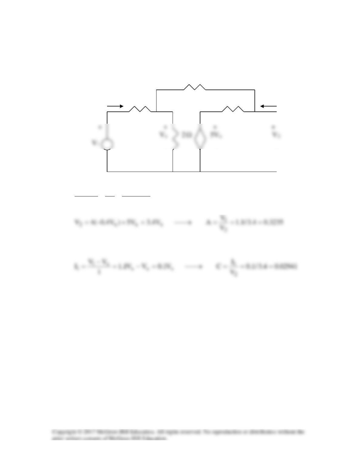
Solution 19.47
To get A and C, consider the circuit below.
6
Ω
I1 1
Ω
4
Ω
I2=0
– – – –
x1
xxxx1
V1.1V
10
V5V
2
V
1
VV =→
−
+=
−
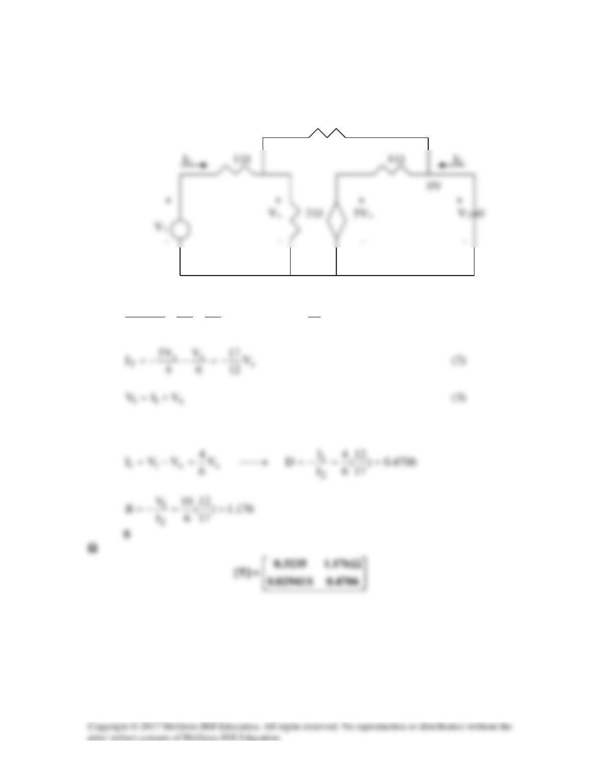
To get B and D, consider the circuit below.
6
Ω
Ω
Ω
x1
xxx1
V
6
10
V
2
V
6
V
1
VV =→+=
−
(1)
From (1) and (3)
Solution 19.48
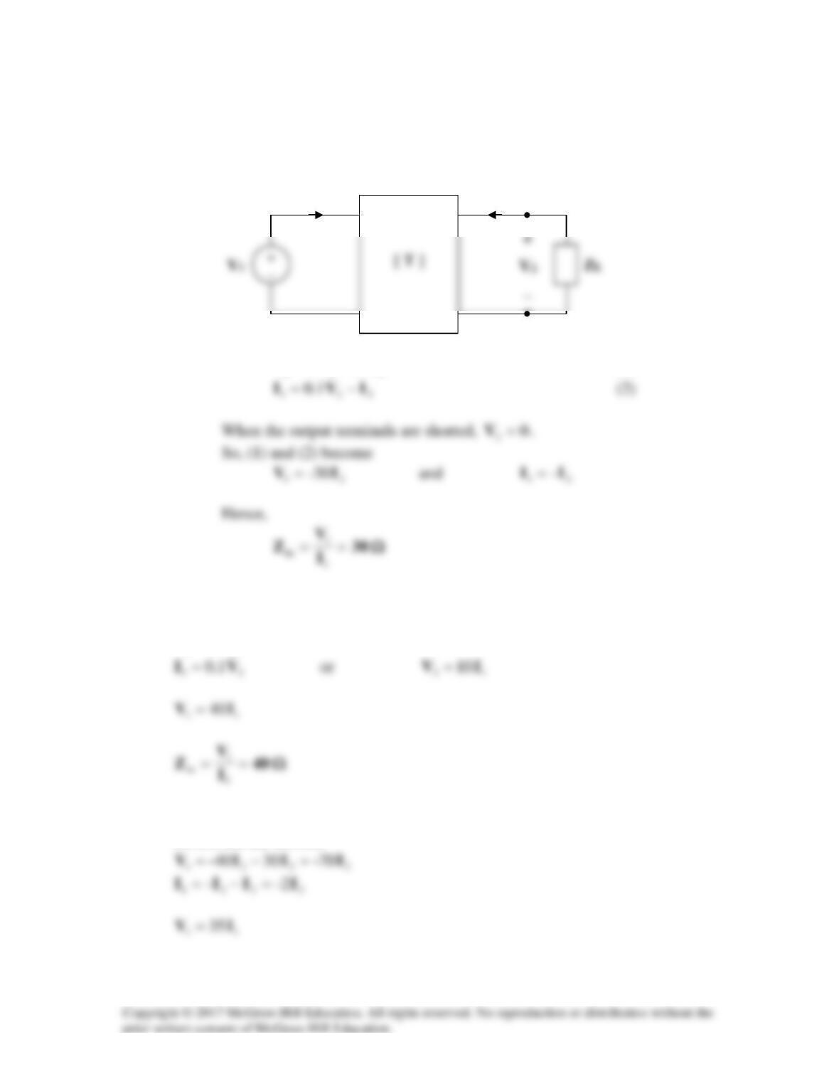
(a) Refer to the circuit below.
221 304 IVV −=
(1)
(b) When the output terminals are open-circuited,
0
2=I
.
So, (1) and (2) become
21 4VV =
(c) When the output port is terminated by a 10-Ω load,
22
I-10V =
.
So, (1) and (2) become
I1
I2
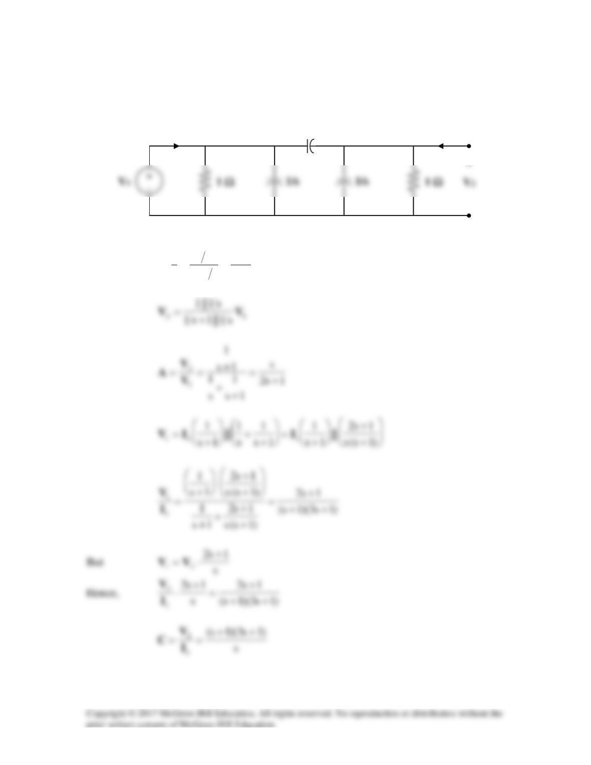
Solution 19.49
To get
A
and
C
, refer to the circuit in Fig.(a).
1s
1
s11
s1
s
1
||1 +
=
+
=
1/s
(a)
(a)
I1
−
I2 = 0
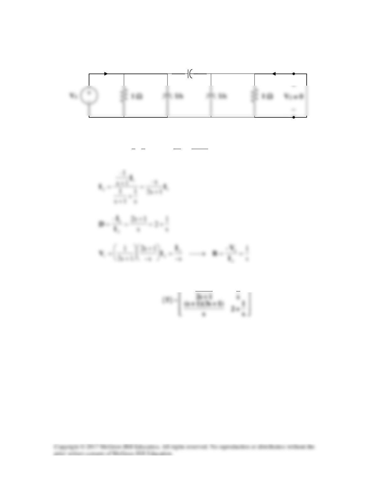
To get
B
and
D
, consider the circuit in Fig. (b).
1s2s2
1
||1
s
1
||
s
1
||1
1
111
+
=
=
=I
IIV
Thus,
1
2
1/s
(b)
(a)
I1
I2