Solution 5.76
The schematic is shown below. IPROBE is inserted to measure io. Upon simulation, the value
of io is displayed on IPROBE as
11.25V
Solution 5.77
The schematic for the PSpice solution is shown below.
3.872mV
3.872mV
0.0100V
6.510mV
4.838mV
Solution 5.78
The circuit is constructed as shown below. We insert a VIEWPOINT to display vo. Upon
simulating the circuit, we obtain,
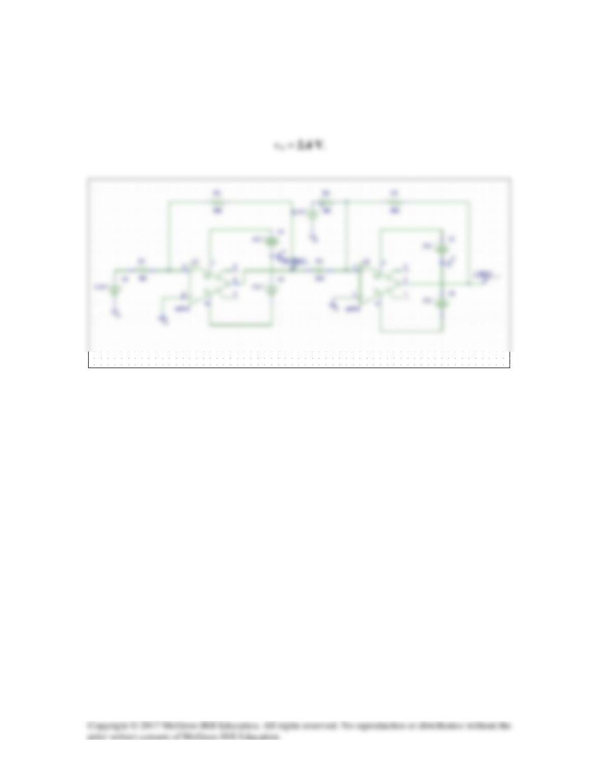
Solution 5.79
The schematic is shown below.
Checking using nodal analysis we get,
For the first op–amp we get va1 = [5/(20+10)]10 = 1.6667 V = vb1.
+
3
V+
7
OS2
5
R3
20k
R4
10k
R5
40k
-20.00V
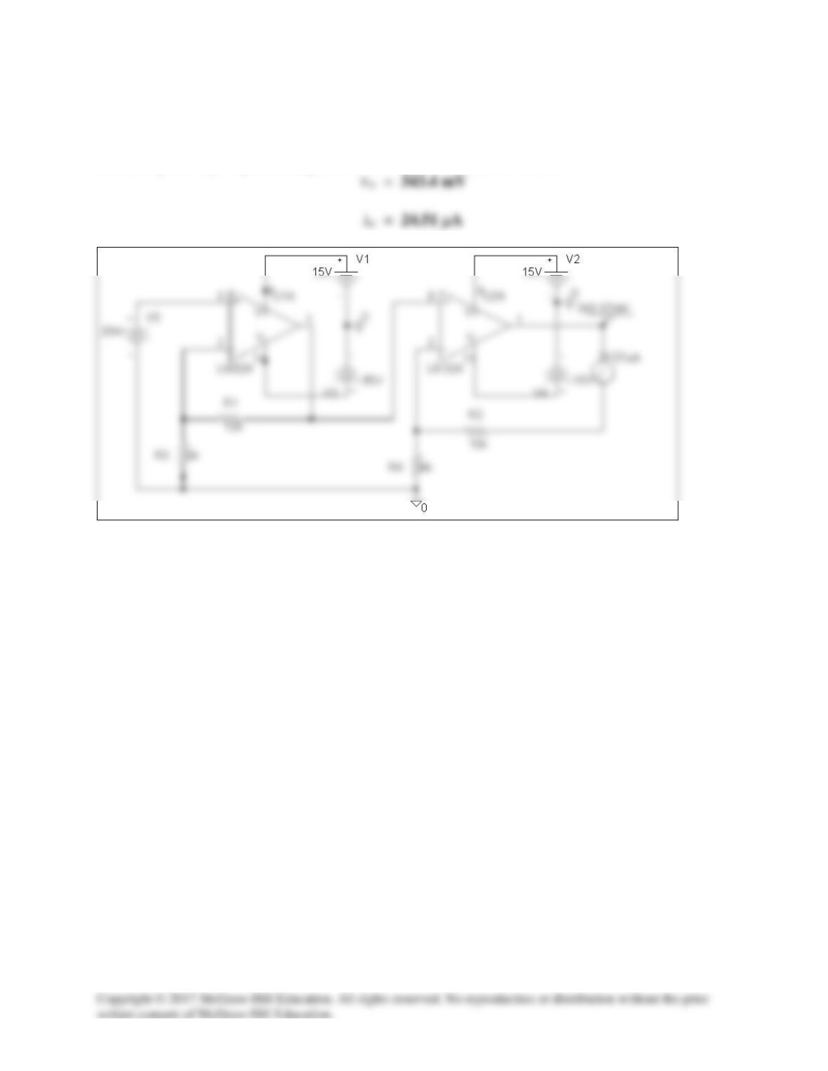
Solution 5.80
The schematic is as shown below. After it is saved and simulated, we obtain
Solution 5.81
The schematic is shown below. We insert one VIEWPOINT and one IPROBE to measure vo
and io respectively. Upon saving and simulating the circuit, we obtain,

Solution 5.82
A four-bit DAC covers a voltage range of 0 to 10 V. Calculate the resolution of the DAC in volts
per discrete binary step.
Solution
The maximum voltage level corresponds to
Solution 5.83
The result depends on your design. Hence, let RG = 10 k ohms, R1 = 10 k ohms, R2 = 20 k
ohms, R3 = 40 k ohms, R4 = 80 k ohms, R5 = 160 k ohms, R6 = 320 k ohms, then,
(a) |vo| = 1.1875 = 1 + 0.125 + 0.0625 = 1 + (1/8) + (1/16) which implies,
Solution 5.84
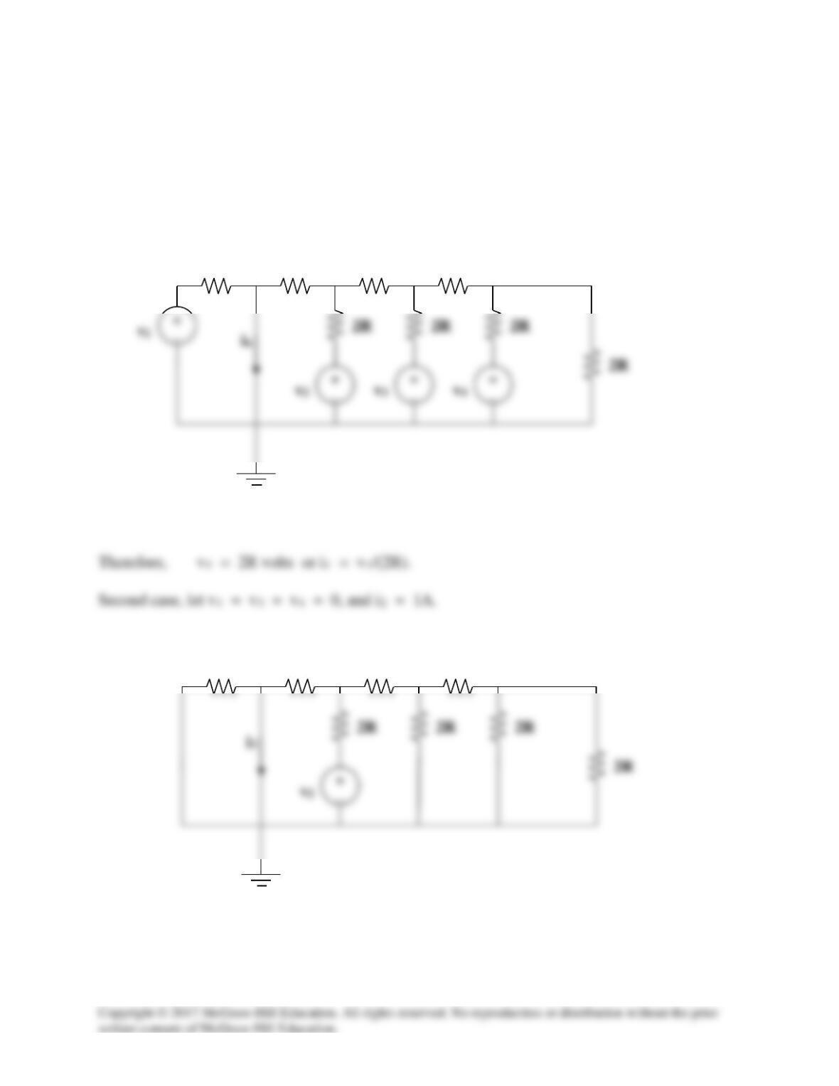
(a) The easiest way to solve this problem is to use superposition and to solve for each term
letting all of the corresponding voltages be equal to zero. Also, starting with each current
contribution (ik) equal to one amp and working backwards is easiest.
For the first case, let v2 = v3 = v4 = 0, and i1 = 1A.
Simplifying, we get,
R
2R
R
R
R
2R
R
R
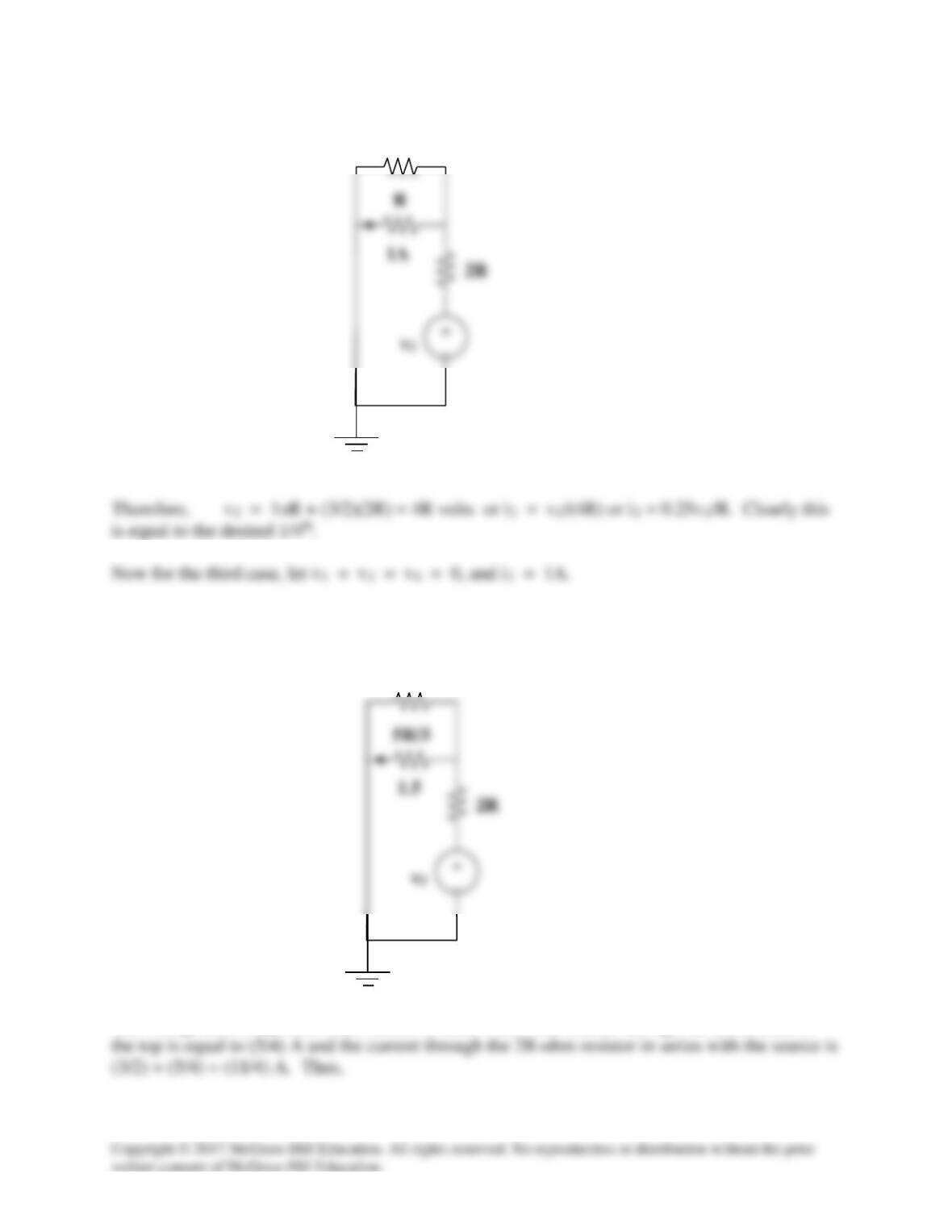
The voltage across the 5R/3-ohm resistor is 5R/2 volts. The current through the 2R resistor at
2R
2R
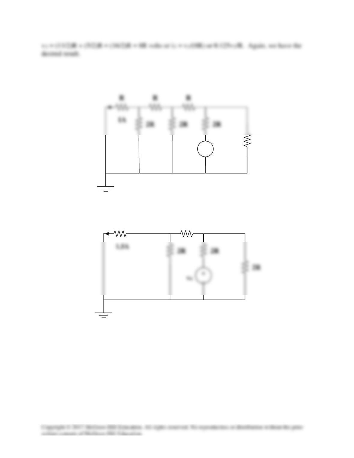
For the last case, v1 = v2 = v3 and i4 = 1A. Simplifying the circuit we get,
2R
v4
+
−
2R
5R/3
R