Solution 3.17
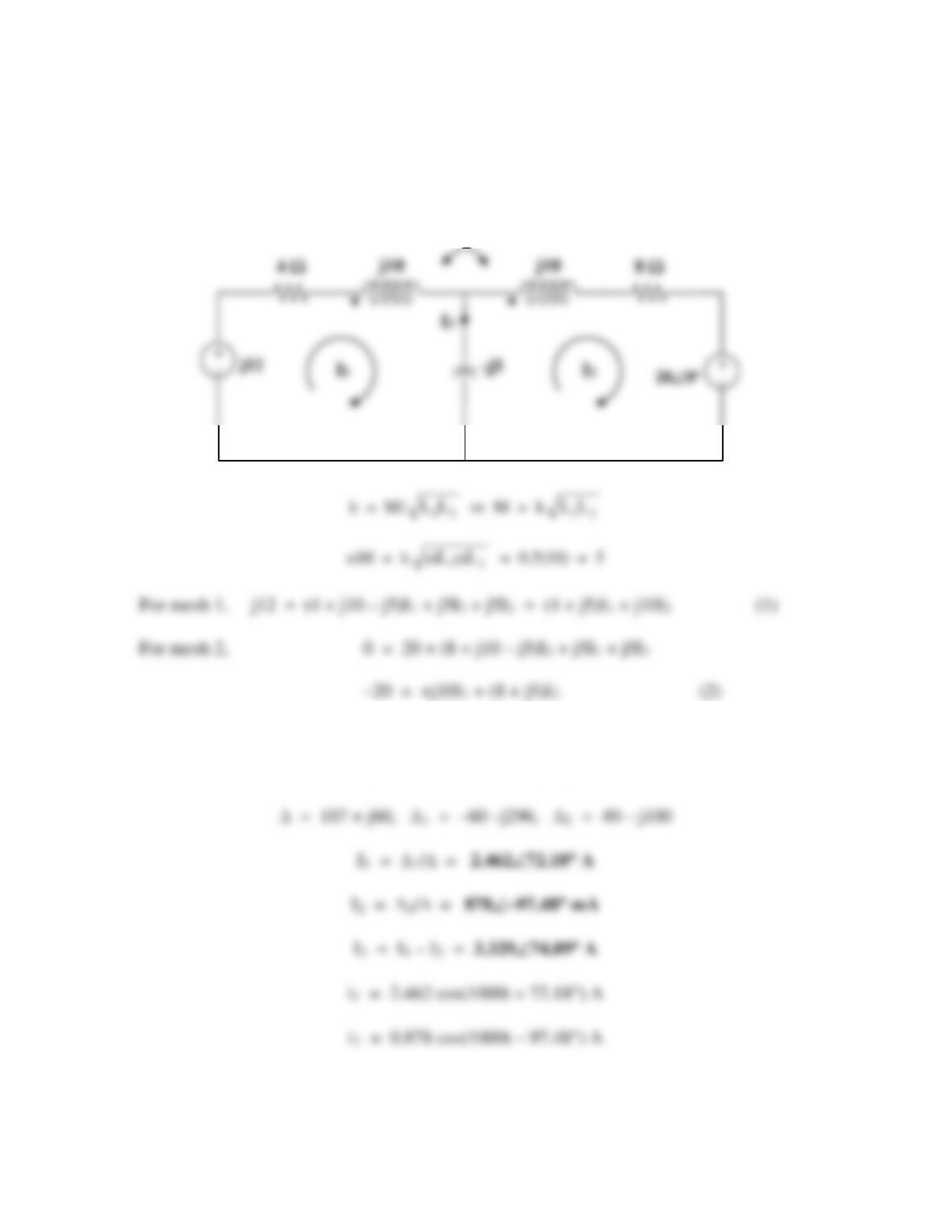
3
40 40
40 2666.67
15 10
jL j Lx
ωω
−
= → = = =
11.384 mH
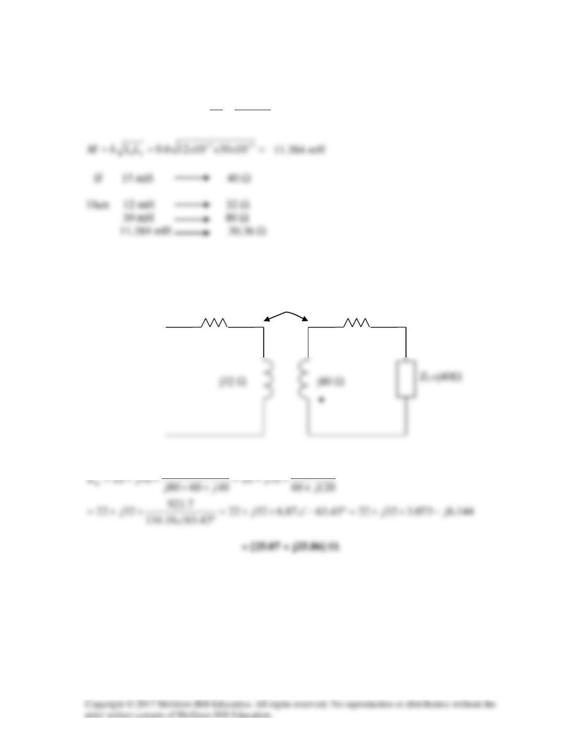
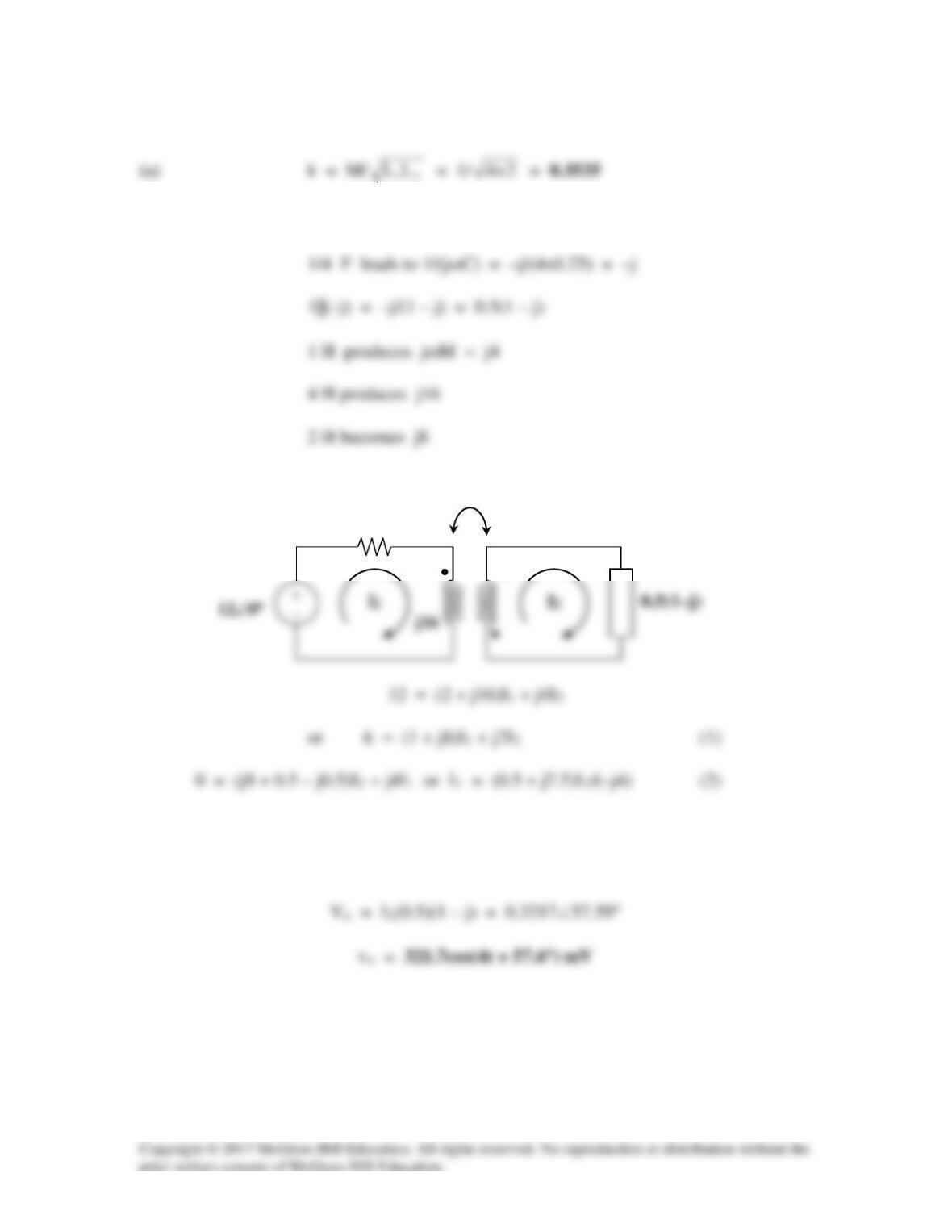
The circuit becomes that shown below.
)36.30(
222
M
ω
2667 rad/s
22 Ω
60 Ω
•
j30.36 Ω
Solution 13.18
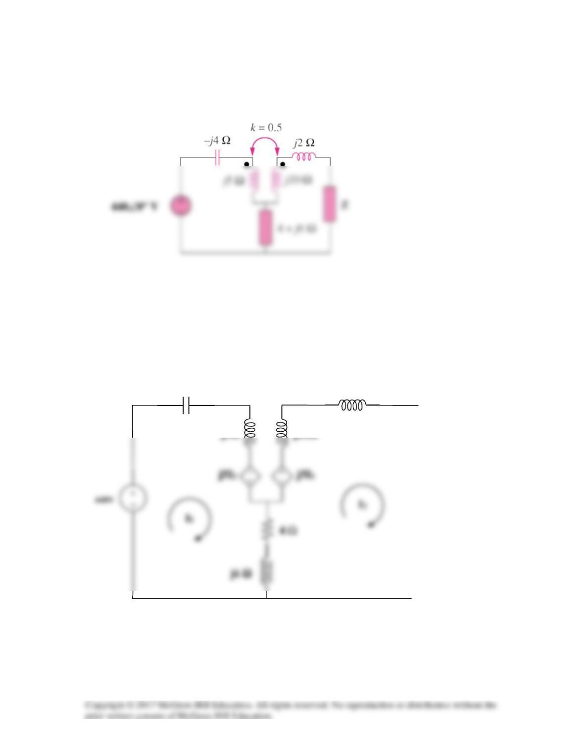
Find the Thevenin equivalent to the left of the load Z in the circuit in Fig. 13.87.
Figure 13.87
For Prob. 1318.
Solution
Replacing the mutually coupled circuit with the dependent source equivalent we get,
–j4 Ω
j2 Ω
j5Ω
j20Ω

Now all we need to do is to find Voc and Isc. To calculate the open circuit voltage, we
note that I2 is equal to zero. Thus,
Mesh 2
Substituting this into equation (1) we get,
Checking using MATLAB we get,
>> Z = [(4+7j) (-4-11j);(-4-11j) (4+28j)]
Z =
Solution 13.19
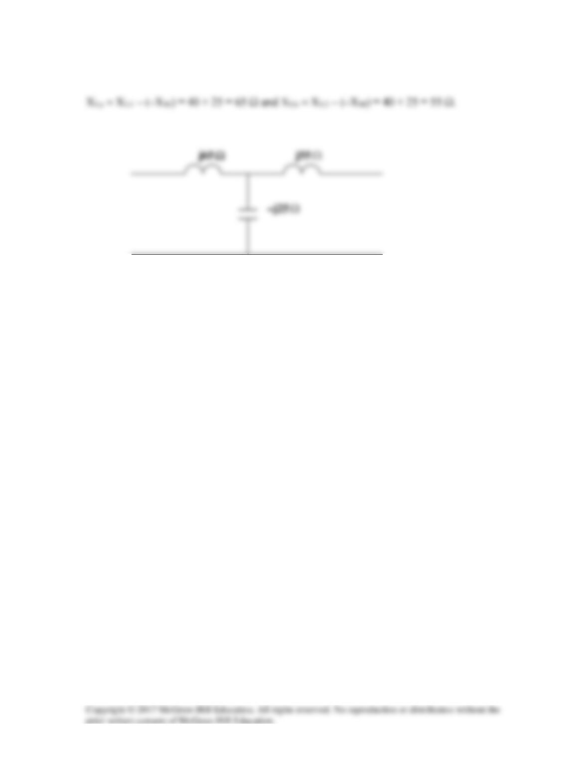
Finally, XC = XM thus, the T-section is as shown below.
Solution 13.20
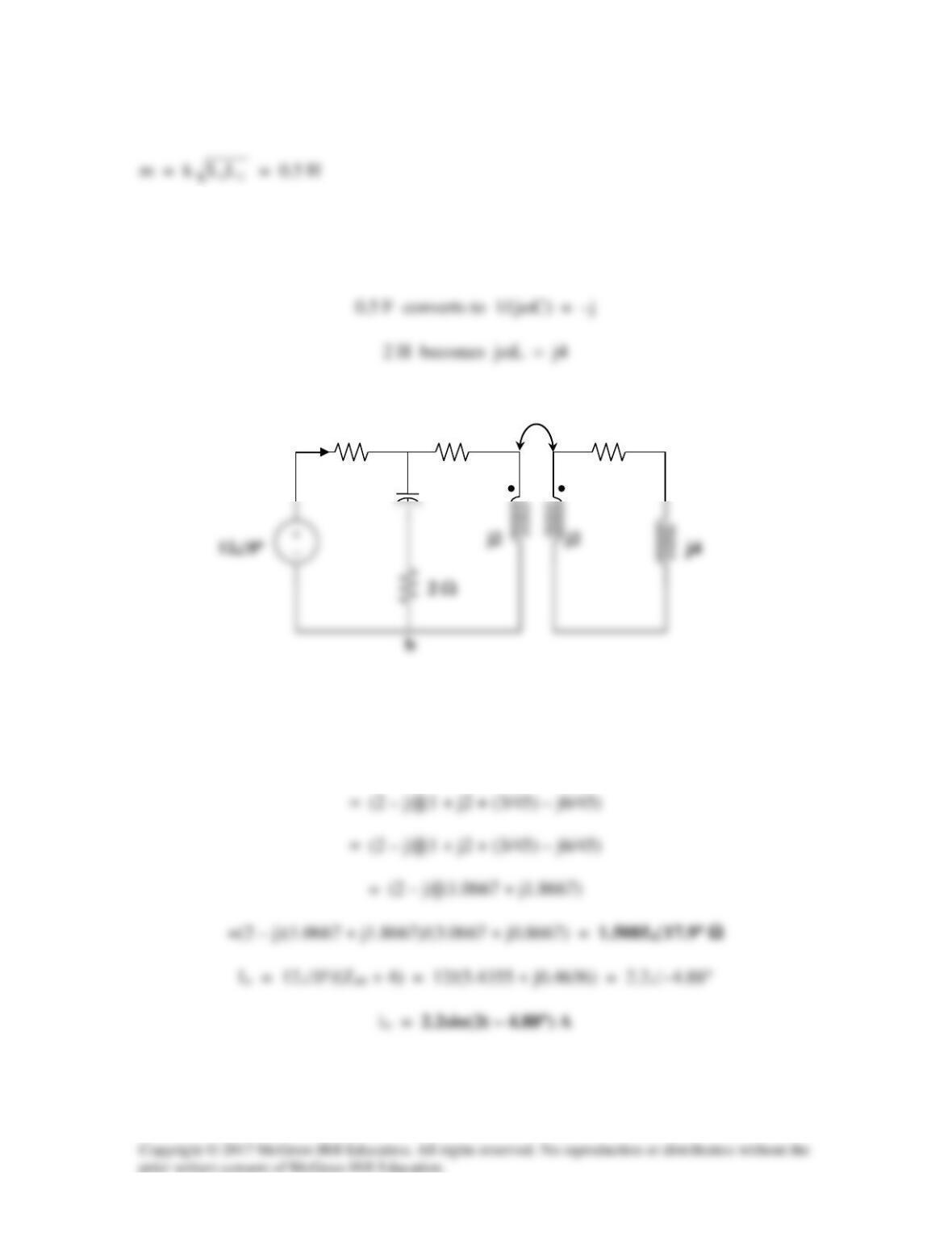
Transform the current source to a voltage source as shown below.
From (1) and (2),
++
++
=
2
1
I
I
5j810j
10j5j4
20
12j
k=0.5
At t = 2 ms, 1000t = 2 rad = 114.6°
Solution 13.21
Using Fig. 13.90, design a problem to help other students to better understand energy in a
coupled circuit.
Although there are many ways to solve this problem, this is an example based on the
same kind of problem asked in the third edition.
Problem
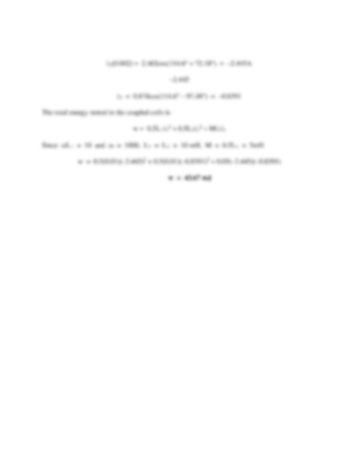
Find I1 and I2 in the circuit of Fig. 13.90. Calculate the power absorbed by the
4-Ω resistor.
Figure 13.90
Solution
For mesh 1, 36∠30° = (7 + j6)I1 – (2 + j)I2 (1)
Solution 13.22
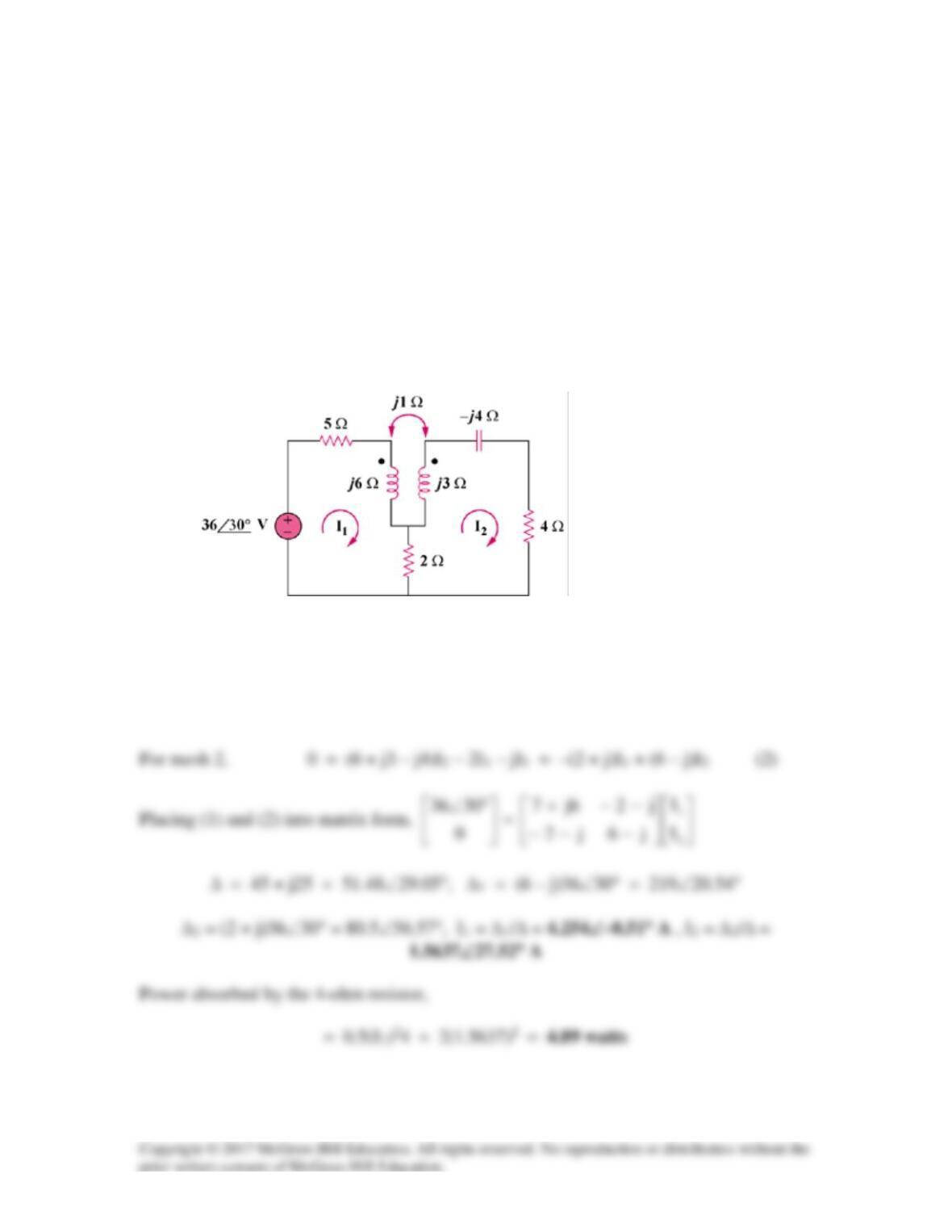
Find current Io in the circuit of Fig. 13.91.
Figure 13.91
For Prob. 13.22.
Solution
With more complex mutually coupled circuits, it may be easier to show the effects of the
coupling as sources in terms of currents that enter or leave the dot side of the coil. Figure
13.85 then becomes,
Ia
120∠0° V
Io
-j50
Note the following,
Ia = I1 – I3
Now all we need to do is to write the mesh equations and to solve for Io.
Loop # 1,
Loop # 2,
j10(I1 – I3) + j80(I2–I1) + j30(I3–I2) – j30(I2 – I1)
Loop # 3,
-j50I3 +j20(I1 –I3) +j60(I3 –I2) +j30(I2 –I1)
Using MATLAB we get,
Chapter 13, Solution 23.
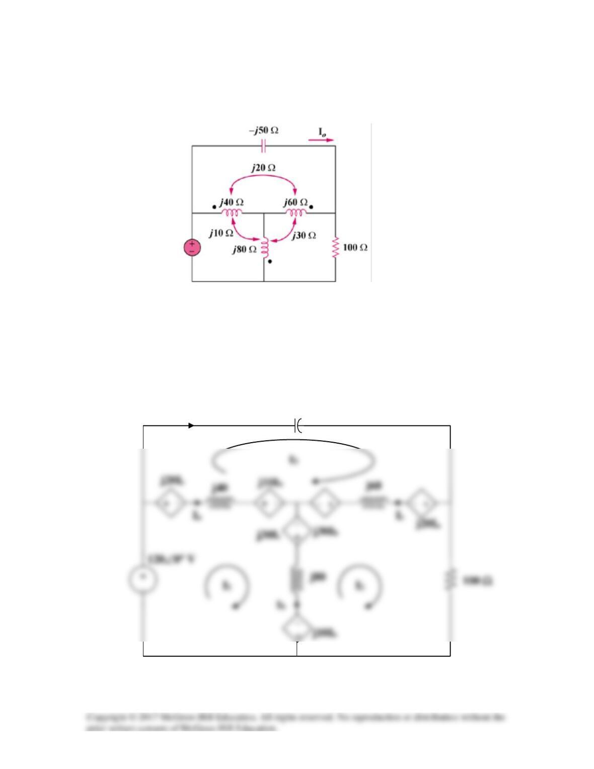
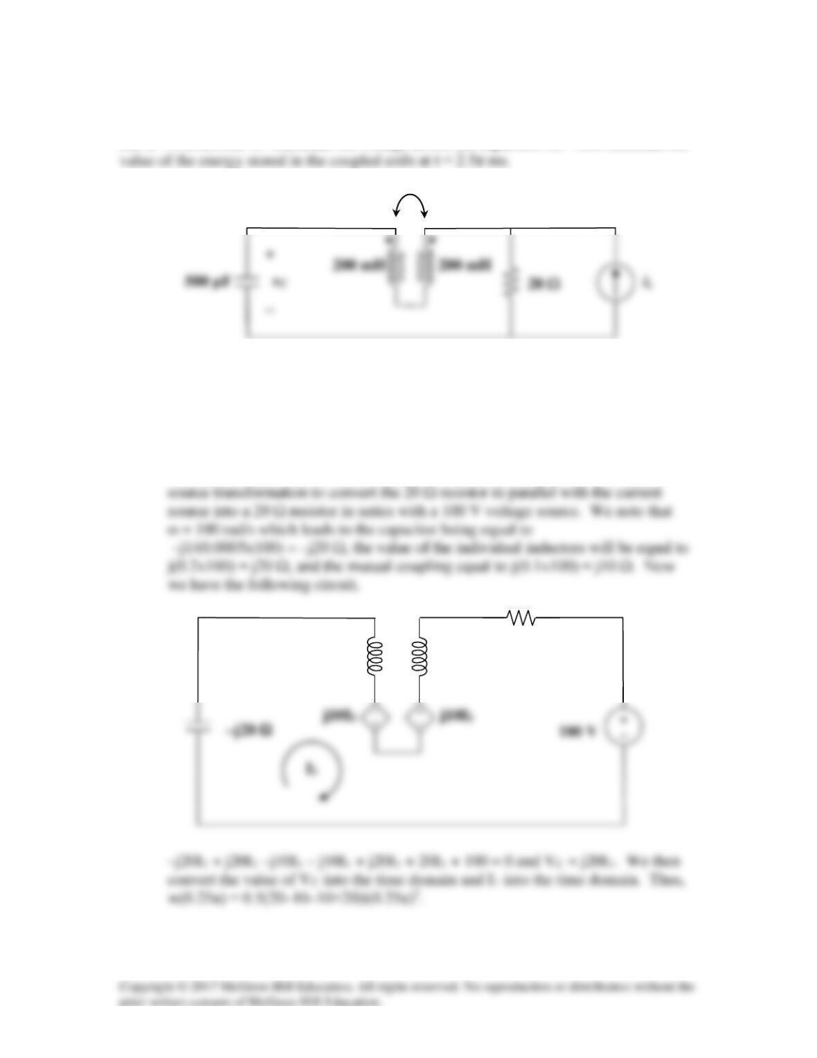
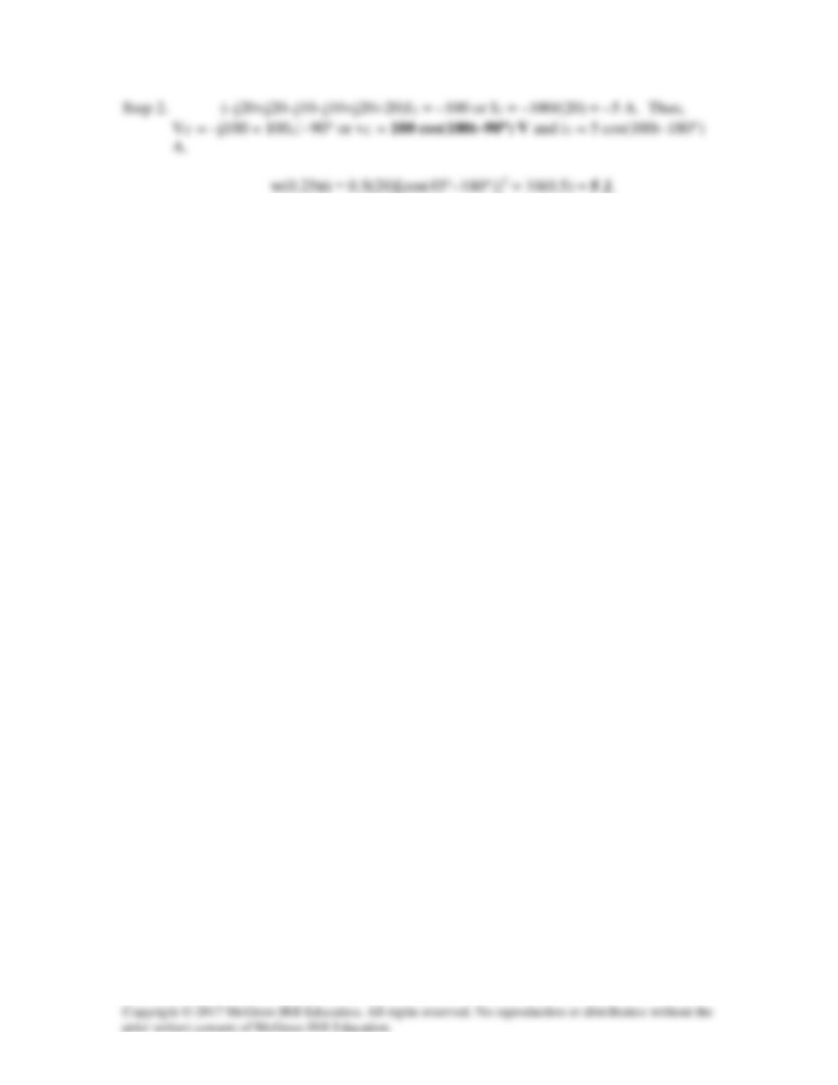
Let is = 5 cos(100t) A. Calculate the voltage across the capacitor, vC. Also calculate the
Figure 13.92
For Prob. 13.23.
Solution
Step 1. First we need to convert the circuit into the frequency domain and convert
the coupled inductors into their dependent source equivalent. Then we can do
–j20 Ω
100 mH
j20 Ω
j20 Ω
20 Ω
Solution 13.24
(b) ω = 4
Substituting (2) into (1),
24 = (–11.5 – j51.5)I2 or I2 = –24/(11.5 + j51.5) = –0.455∠–77.41°
j4
2 Ω
j8
(c) From (2), I1 = (0.5 + j7.5)I2/(–j4) = 0.855∠–81.21°
Solution 3.25
We transform the circuit to frequency domain as shown below.
12sin2t converts to 12∠0°, ω = 2
Applying the concept of reflected impedance,
Zab = (2 – j)||(1 + j2 + (1)2/(j2 + 3 + j4))
j1
1 Ω
4 Ω
Io
3 Ω
a
–j1
Solution 13.26
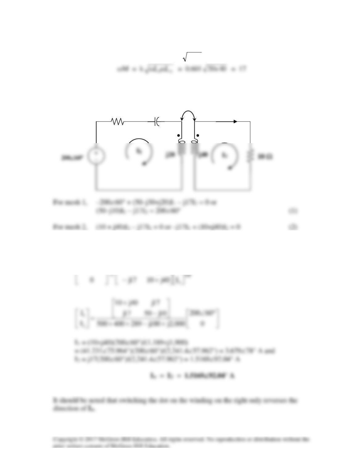
M = k 21LL
The frequency-domain equivalent circuit is shown below.
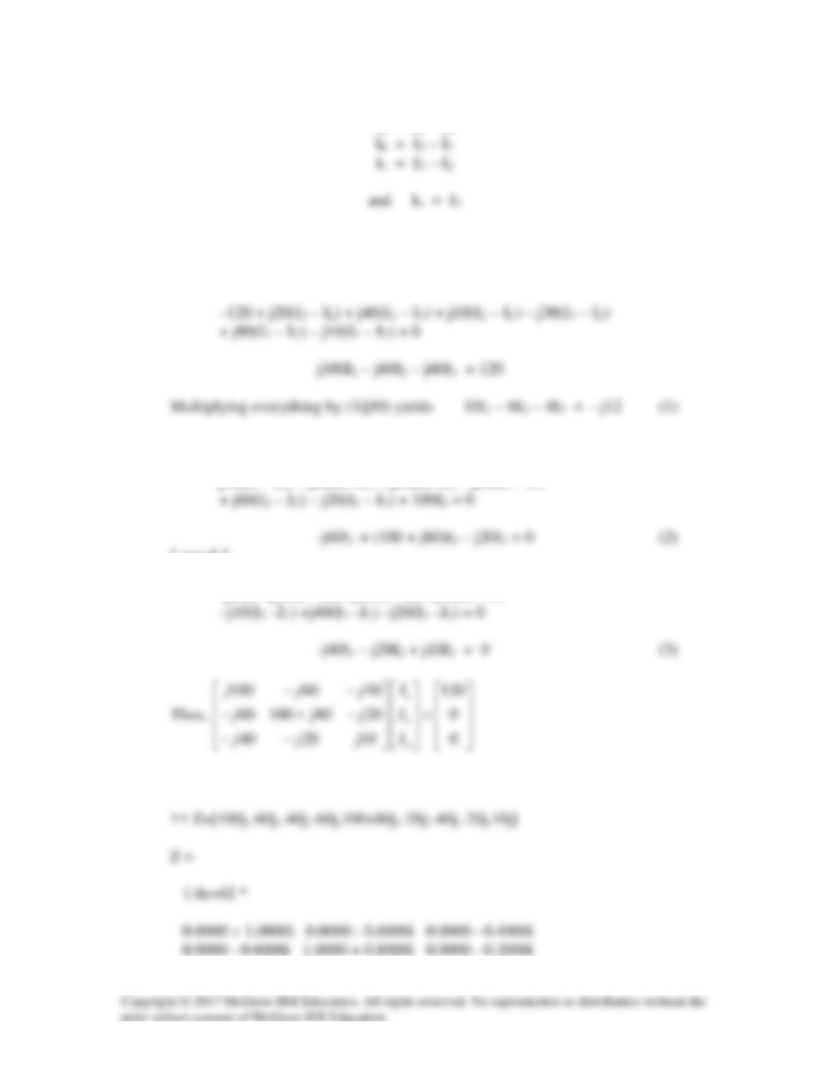
In matrix form,
−−
°∠
I
17j10j50
60200
1
j17
50 Ω
–j30
Io
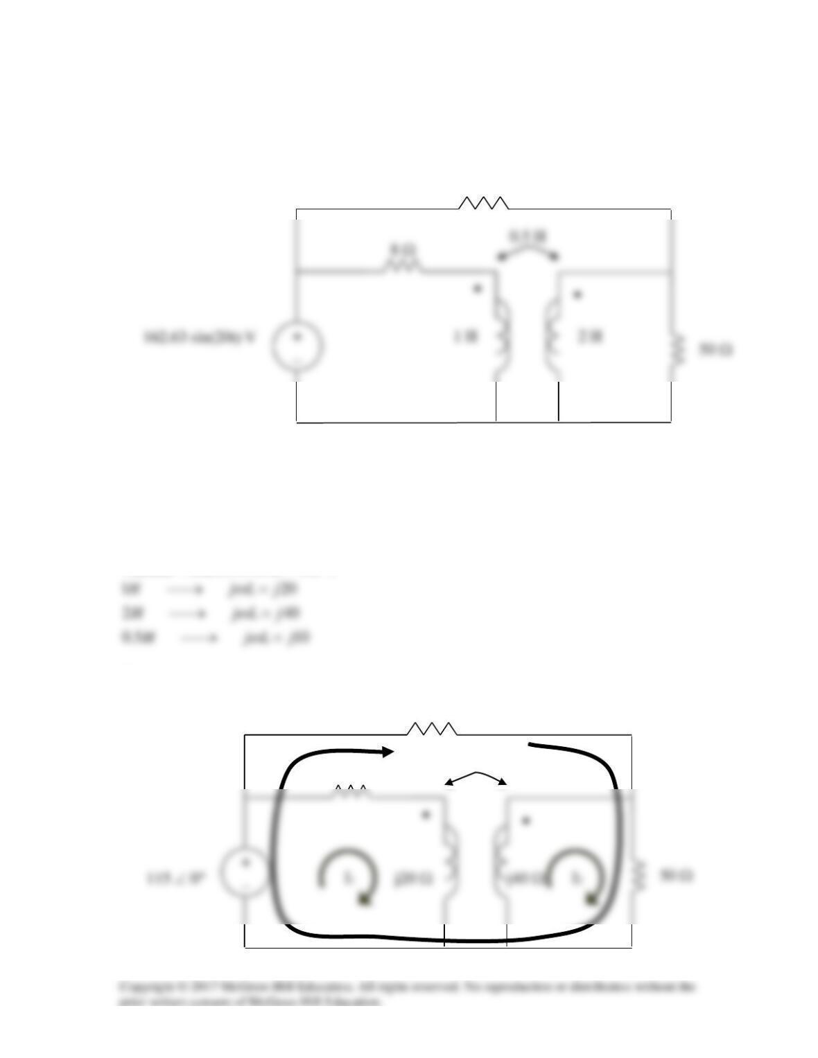
Solution 13.27
Find the average power delivered to the 50-Ω resistor in the circuit of Fig. 13.96.
50 Ω
Figure 13.96
For Prob. 13.27.
Solution
Vs(rms) = 162.63/1.4142 = 115 V
We apply mesh analysis to the circuit as shown below.
50 Ω
8 Ω
10 Ω
j10 Ω
I
3
10 Ω
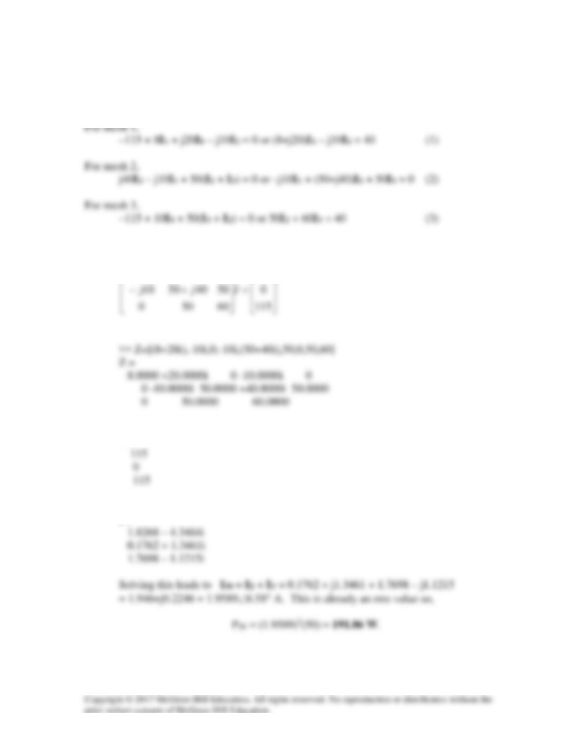
To make the problem easier to solve, let us have I3 flow around the outside loop as
shown.
In matrix form, (1) to (3) become
−+
115
010208
jj
>> V=[40;0;40]
V =
>> I=inv(Z)*V
I =
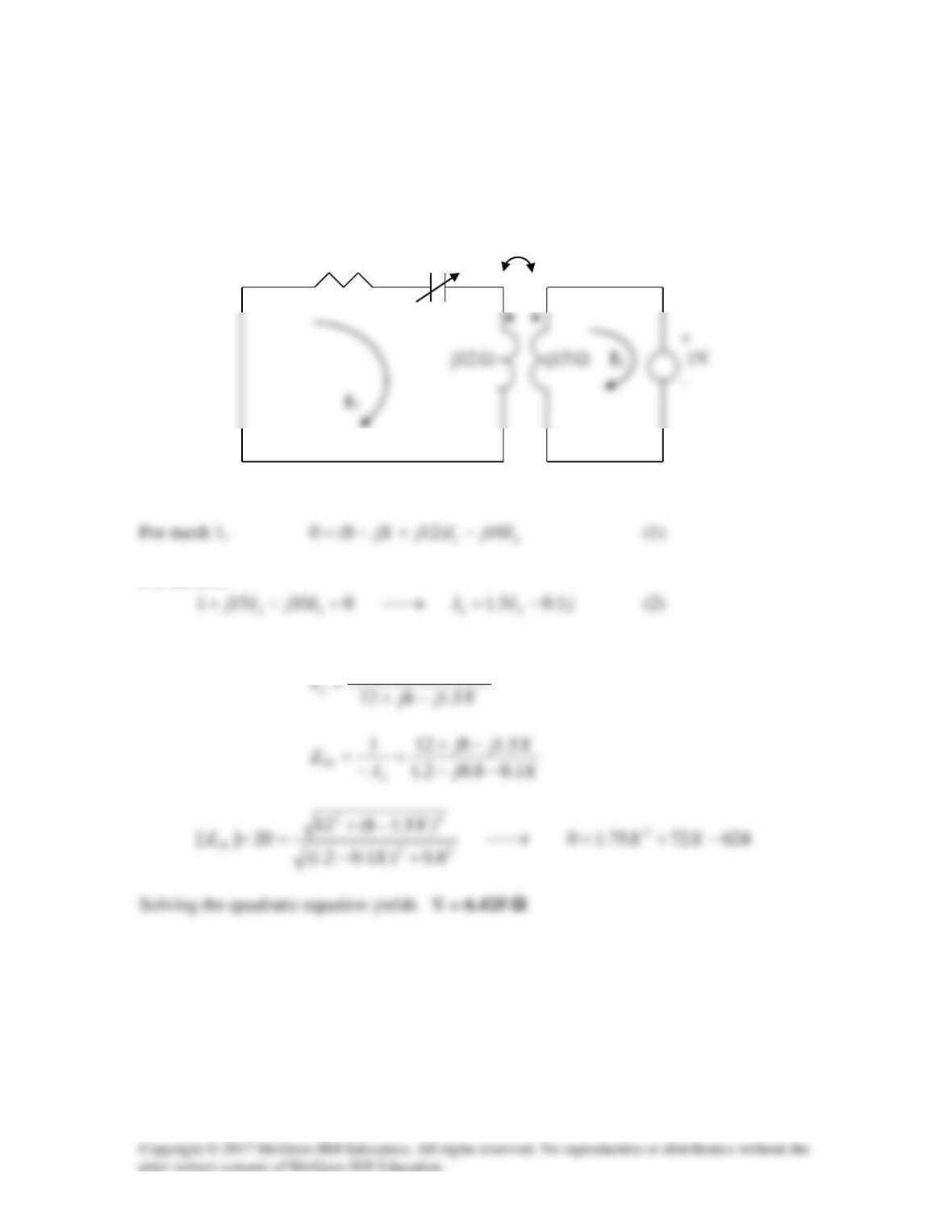
Solution 13.28
We find ZTh by replacing the 20-ohm load with a unit source as shown below.
j10
Ω
8
Ω
–jX
Ω
Ω
For mesh 2,
Substituting (2) into (1) leads to
Xj
1.08.02.1
++−