Solution 14.20
Design a more complex problem than given in Prob. 14.10, to help other students to
better understand how to determine the Bode magnitude and phase plots of a given
transfer function in terms of jω. Include at least a second order repeated root.
Although there are many ways to solve this problem, this is an example based on the
same kind of problem asked in the third edition.
Problem
Sketch the magnitude phase Bode plot for the transfer function
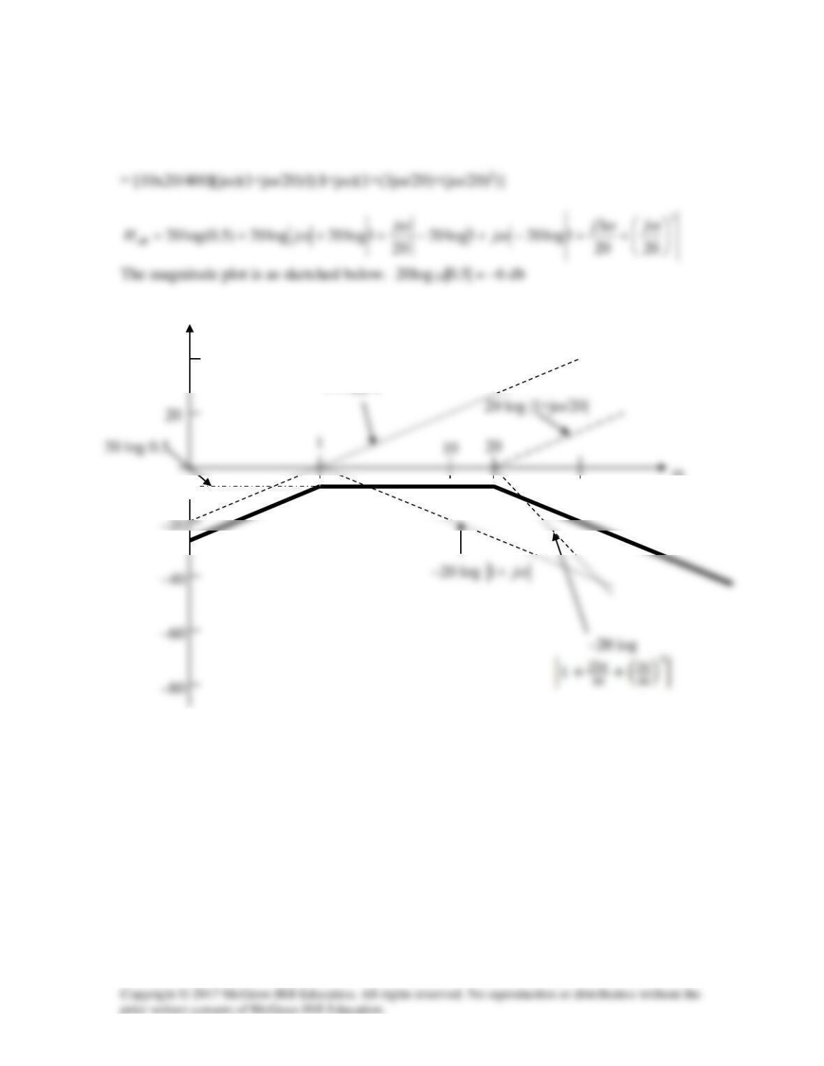
Solution
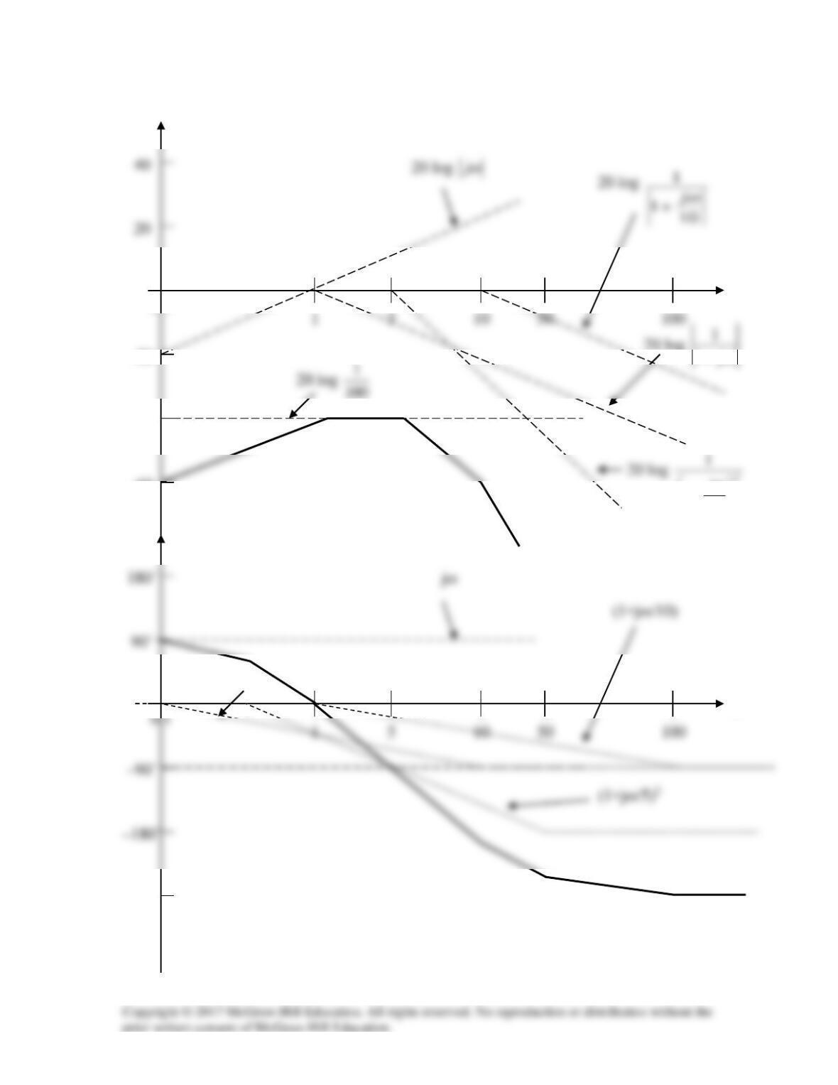
The magnitude and phase plots are shown below.
0.1
ω
15
j
ω
+
-40
-20
-60
1j
ω
+
0.1
–180˚
ω
–270˚
(1+jω)
Solution 14.21
H(ω) = 10(jω)(20+jω)/[(1+jω)(400+60jω–ω2)]
0.1
db
10
ω
40
20log|jω|
Solution 14.22
Find the transfer function H(ω) with the Bode magnitude plot shown in Fig. 14.74.
Figure 14.74
For Prob. 14.22.
Solution
1log200 10 =→= kk
ω
(rad/s)
–20
Solution 14.23
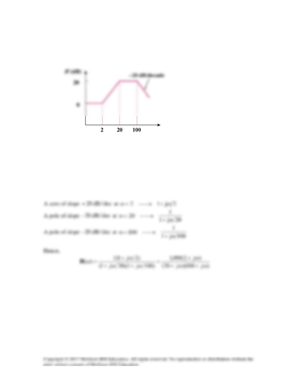
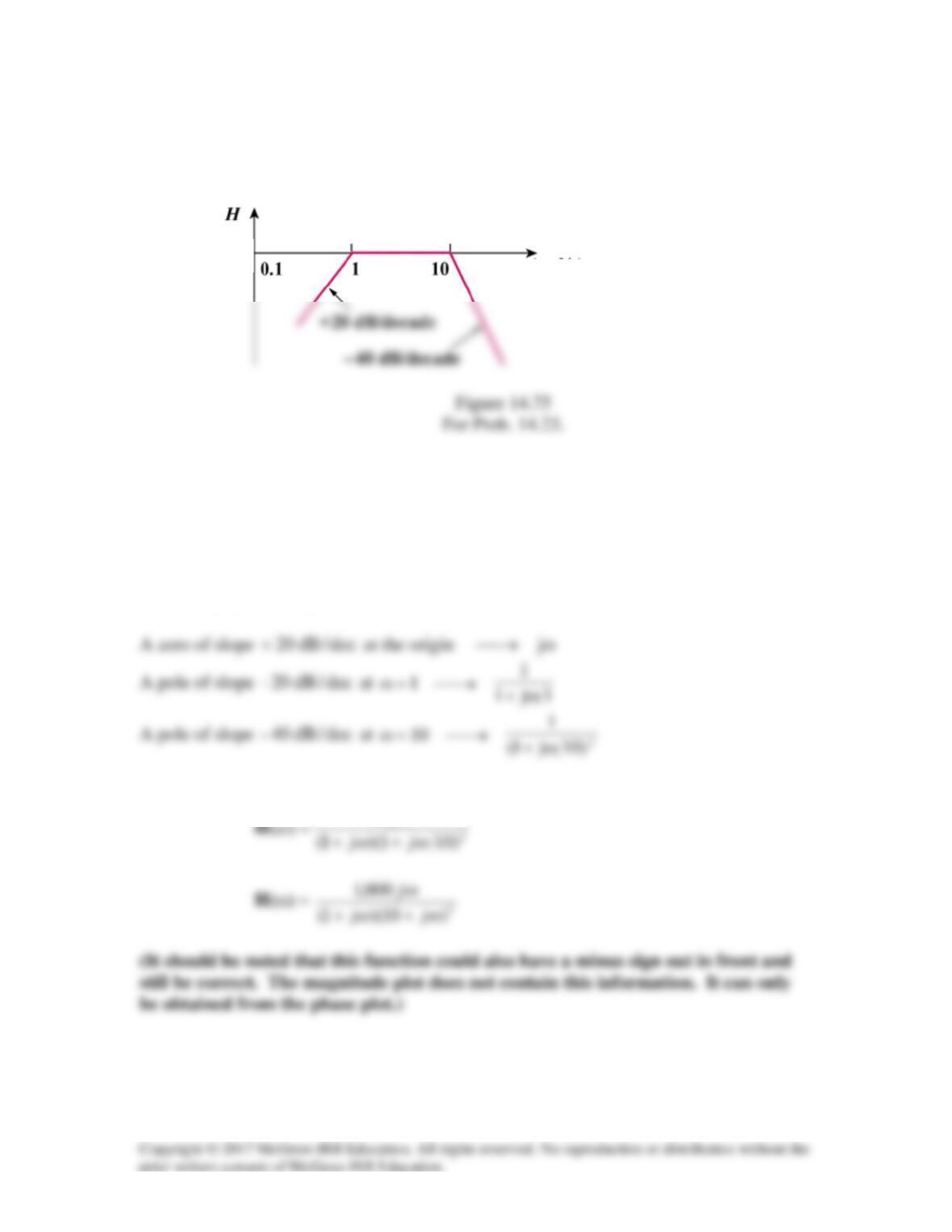
The Bode magnitude plot of H(ω) is shown in Fig. 14.75. Find H(ω).
Solution
The initial slope indicates we have jω in the numerator. Our approach to plotting requires
the plot of jω to cross 0db at ω = 1 rad/s. Since it crosses at 20db, that indicates that the
overall gain is 20db or,
20 = 20log10|gain| the gain has to be 10.
Hence,
10
ω
j
(db)
0
ω (rad/s)
20
Solution 14.24
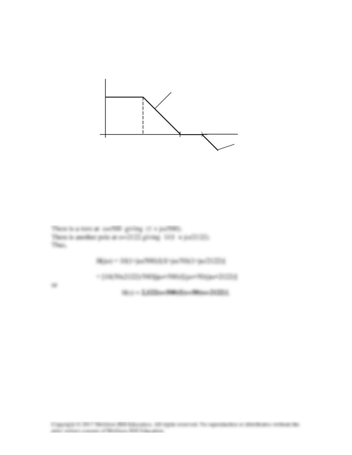
The magnitude plot in Fig. 14.76 represents the transfer function of a preamplifier. Find
H(s).
Figure 14.76
For Prob. 14.24.
Solution
20 = 20log10|gain| or gain = 10.
There is a pole at ω=50 giving 1/(1+jω/50)
H(dB)
0
20
50
500
20 dB/dC
20 dB/dC
2122
ω
5
Solution 14.25
s/krad5
)101)(1040(
1
LC
1
6–3–
0=
××
==ω
==ω R)( 0
Z
Ωk2
ω
ω
4
4
0
0
0
Z
ω
−
ω
+=ω C
2
L
2
jR)2(
0
0
0
Z
ω
−ω+=ω C2
1
L2jR)2(
0
00
Z
Solution 14.26
Design a problem to help other students to better understand ωo, Q, and B at resonance in
series RLC circuits.
Although there are many ways to solve this problem, this is an example based on the
same kind of problem asked in the third edition.
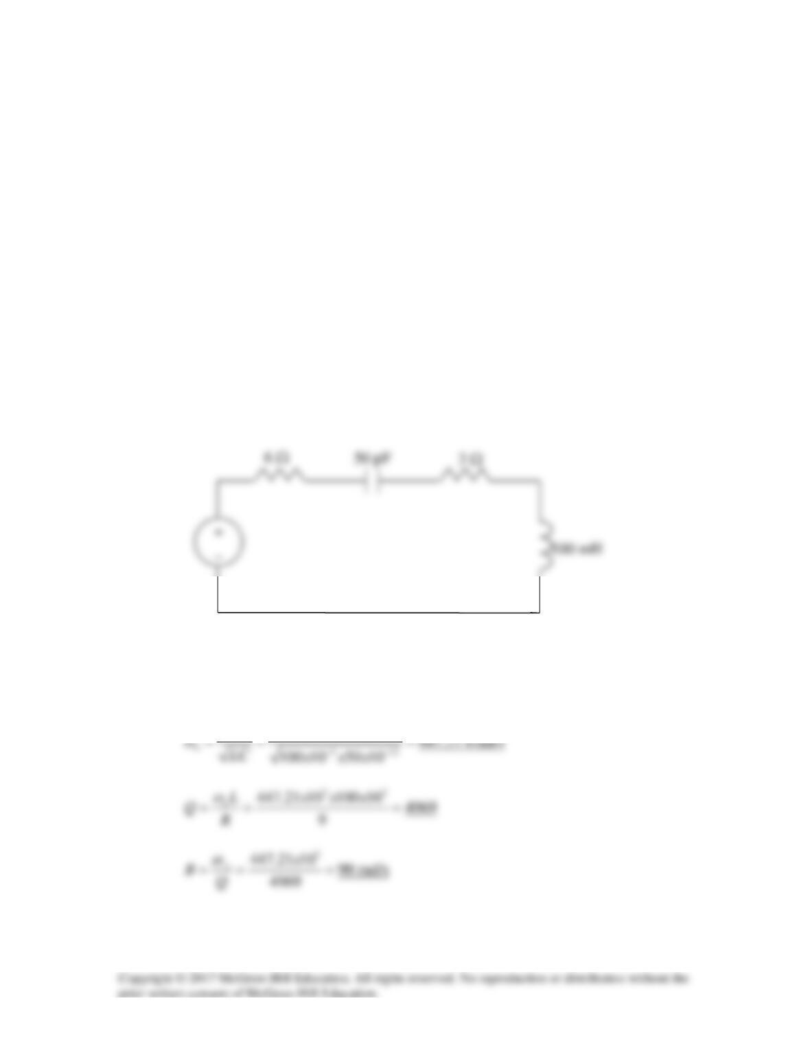
Problem
A coil with resistance 3 Ω and inductance 100 mH is connected in series with a capacitor
of 50 pF, a resistor of 6 Ω, and a signal generator that gives 110V-rms at all frequencies.
Calculate ωo, Q, and B at resonance of the resultant series RLC circuit.
Solution
Consider the circuit as shown below. This is a series RLC resonant circuit.
R = 6 + 3 = 9 Ω
11
Solution 14.27
2
11
40 40
oLC
LC
ω
= = → =
Solution 14.28
Design a series RLC circuit with B = 20 rad/s and
ω
0 = 1,000 rad/s. Find the circuit’s Q.
Let R = 10 Ω.
Solution
Ω= 10R
.
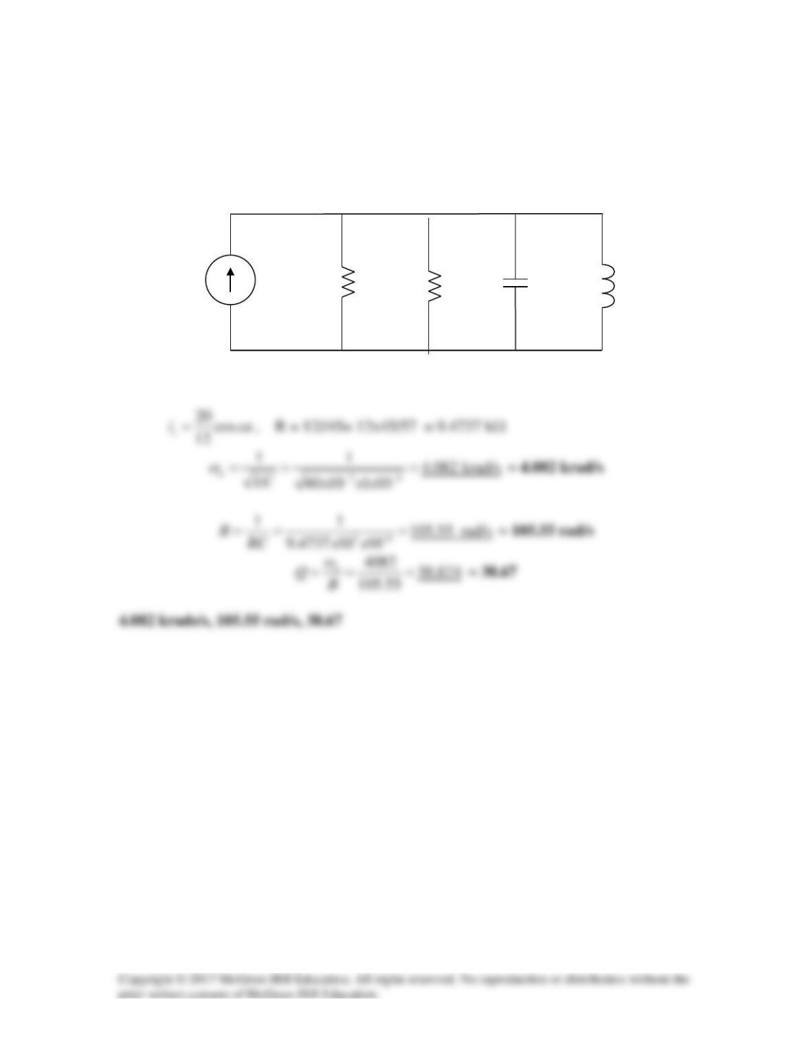
Solution 14.29
We convert the voltage source to a current source as shown below.
12 k
60 mH
1 µF
i
s
45 k
Solution 14.30
(a) fo = 15,000 Hz leads to ωo = 2πfo = 94.25 krad/s = 1/(LC)0.5 or
Solution 14.31
Design a parallel resonant RLC circuit with
ω
0 = 100 krad/s and a bandwidth of 10
krad/s.
Additionally what is the value of Q?
Solution
Step 1. We note that,
Solution 14.32
Design a problem to help other students to better understand the quality factor, the
resonant frequency, and bandwidth of a parallel RLC circuit.
Although there are many ways to solve this problem, this is an example based on the
same kind of problem asked in the third edition.
Problem
A parallel RLC circuit has the following values:
R = 60 Ω, L = 1 mH, and C = 50 µF
Find the quality factor, the resonant frequency, and the bandwidth of the RLC circuit.
Solution
11
4.472 krad/s
ω
= = =
Solution 14.33
A parallel resonant circuit has a bandwidth of 40 krad/s and the half power frequencies
are ω1 = 4.98 Mrad/s and ω2 = 5.02 Mrad/s, calculate the quality factor and resonant
frequency.
Solution
Solution 14.34
A parallel RLC circuit has an R = 100 kΩ, L = 100 mH, and a C = 10 µF, determine the
value of Q, the resonant frequency, and the bandwidth. If R = 200 kΩ, how does that
effect the values of Q, resonant frequency, and the bandwidth?
Solution
Since,
ωo =
1
LC
Solution 15.35
A parallel RLC circuit has an R = 10 kΩ, an L = 100 mH, and a resonant frequency of
200 krad/s, calculate the value of C, the value of the quality factor, and the bandwidth.
Solution
Since,
ωo =
1
LC
or LC = 1/(ωo)2
Solution 14.36
It is expected that a parallel RLC resonant circuit has a midband admittance of
25 × 10–3 S, quality factor of 120, and a resonant frequency of 200 krad/s. Calculate the
values of R, L, and C. Find the bandwidth and the half-power frequencies.
Solution
At resonance,
=
×
==→=
3–
1025
1
Y
1
R
R
1
Y
Ω40
Solution 4.37
s/rad5000
LC
1
0
==ω
==ω→=ω R)(
R
1
)( 00 ZY
Ω
k2
Solution 14.38
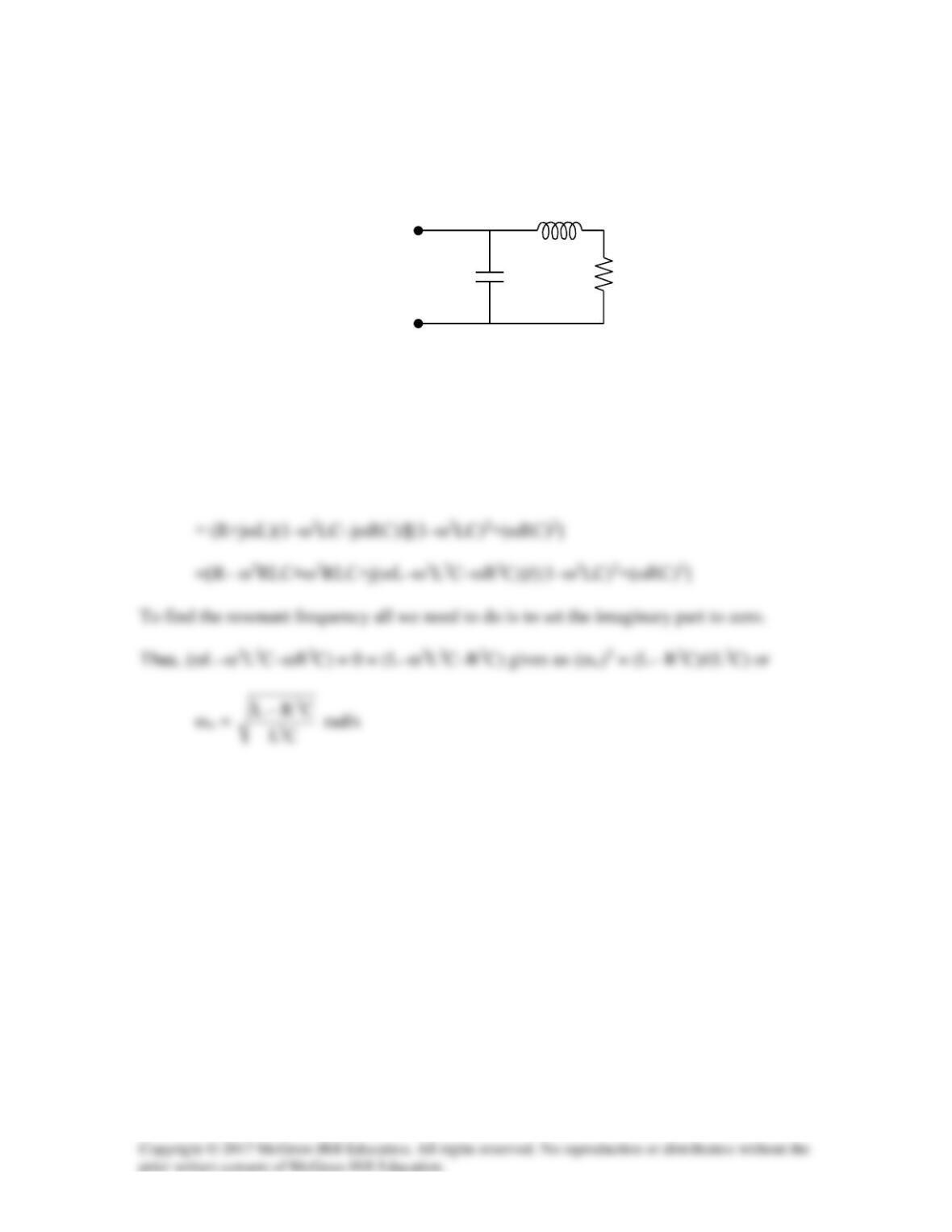
Find the resonant frequency of the circuit in Fig. 14.78.
Figure 14.78
For Prob. 14.38.
Solution
Z = (1/(jωC))(R+jωL)/[(1/(jωC))+R+jωL] = (R+jωL)/(1+jωRC–ω2LC)
C
R
L