Solution 9.40
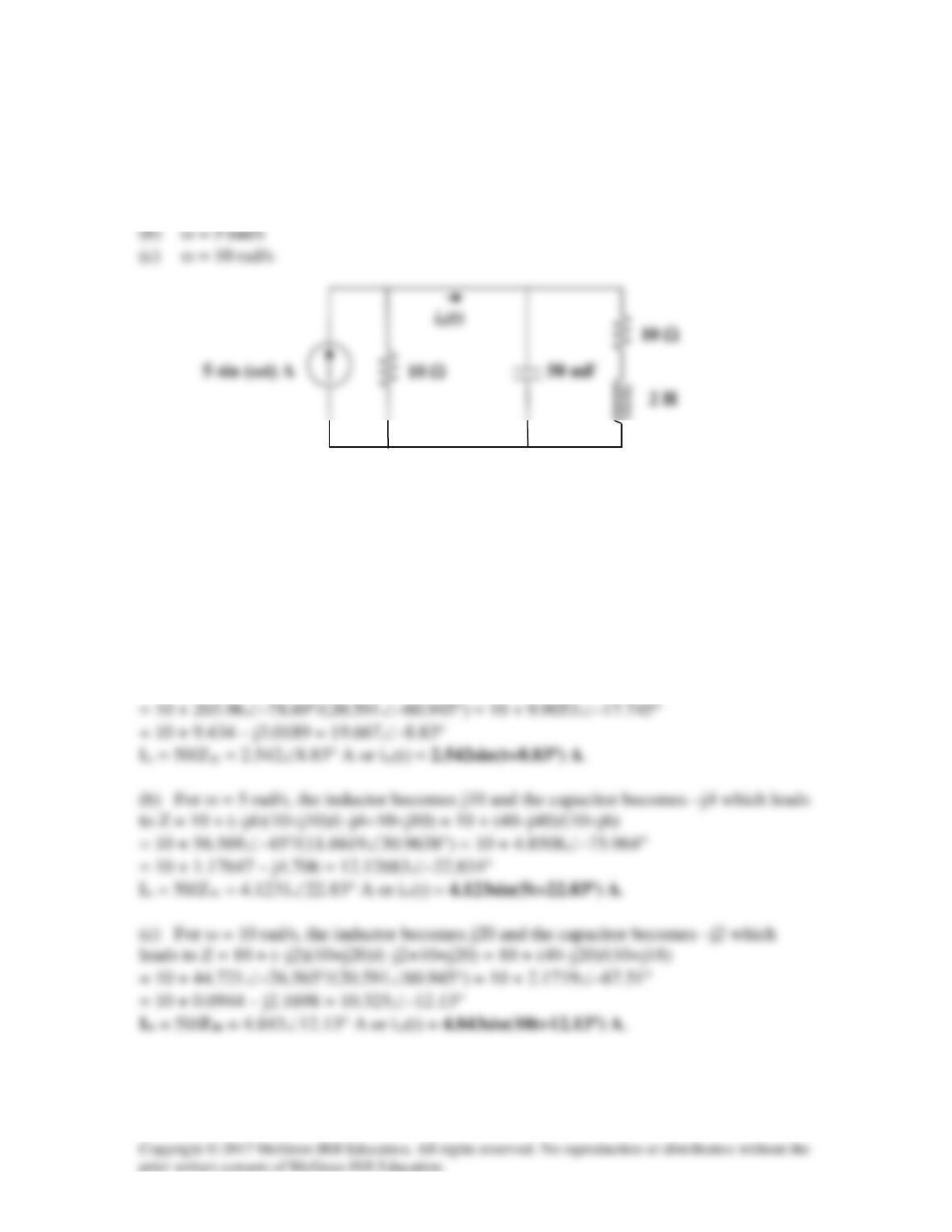
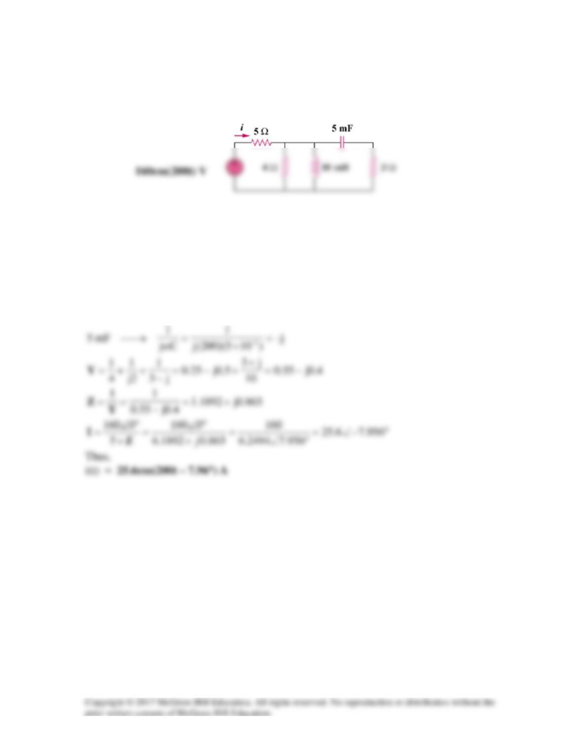
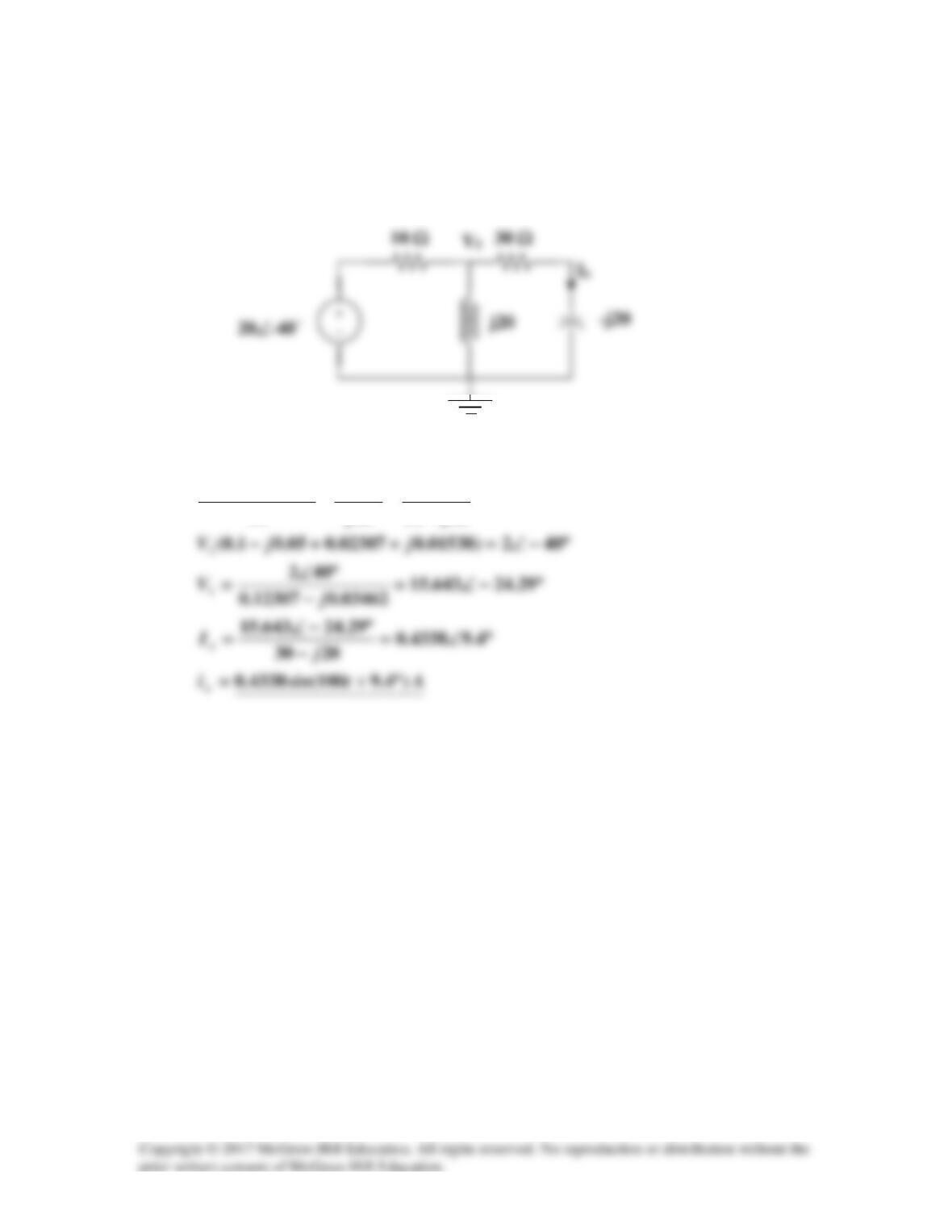
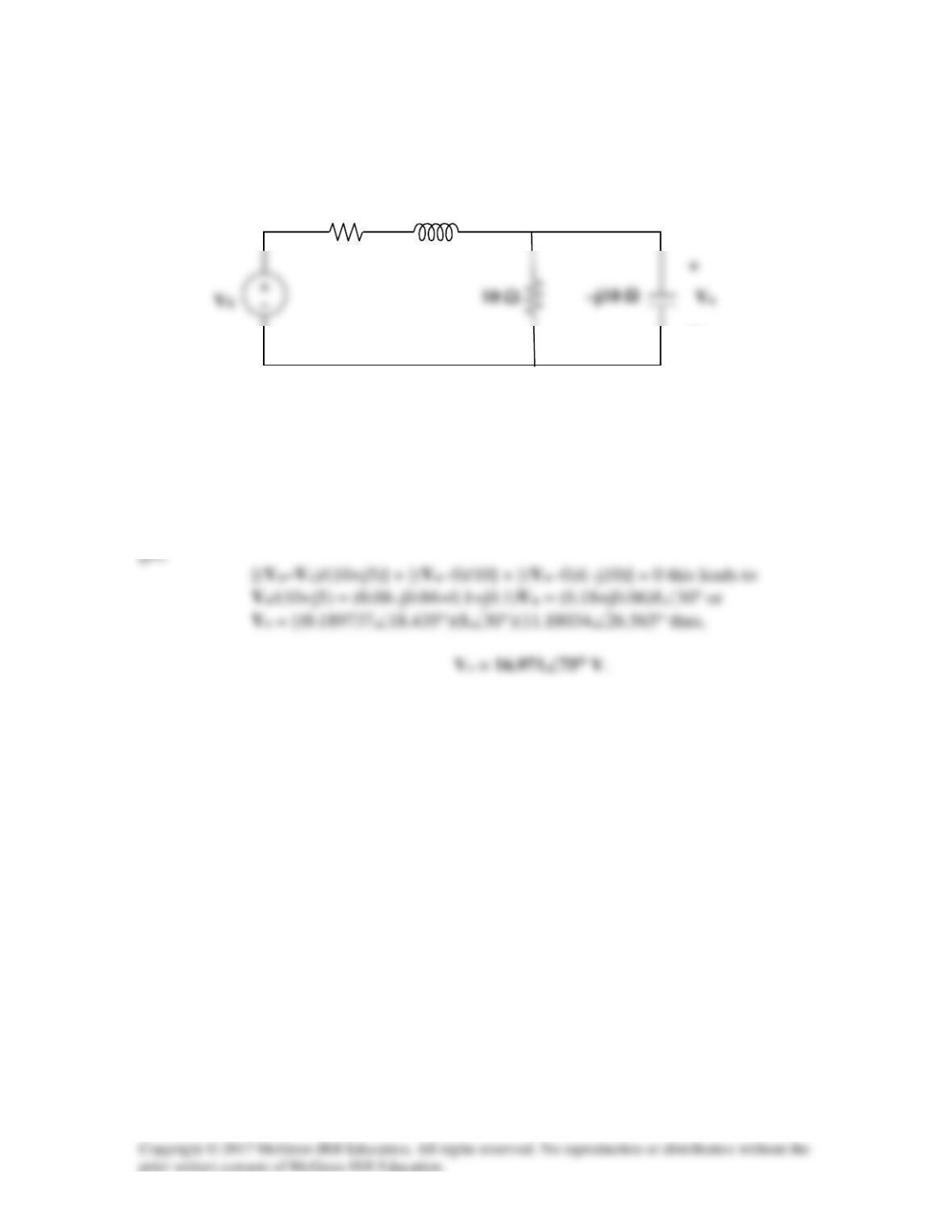
In the circuit of Fig. 9.47, find io(t) when:
(a) ω = 1 rad/s
Figure 9.47
For Prob. 9.40.
Solution
It will help to convert the current source resistor into the Thevenin equivalent or 50 V in
series with 10 Ω.
(a) For ω = 1 rad/s, the inductor becomes j2 and the capacitor becomes –j20 which leads
to Z = 10 + (–j20)(10+j2)/(–j20+10+j2) = 10 + (40–j200)/(10–j18)
Solution 9.41
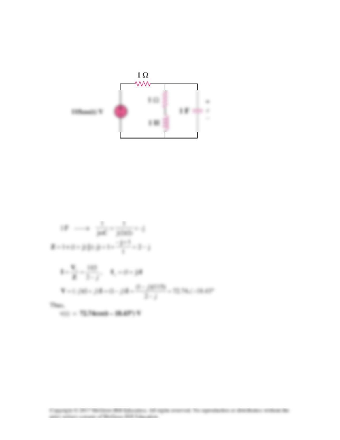
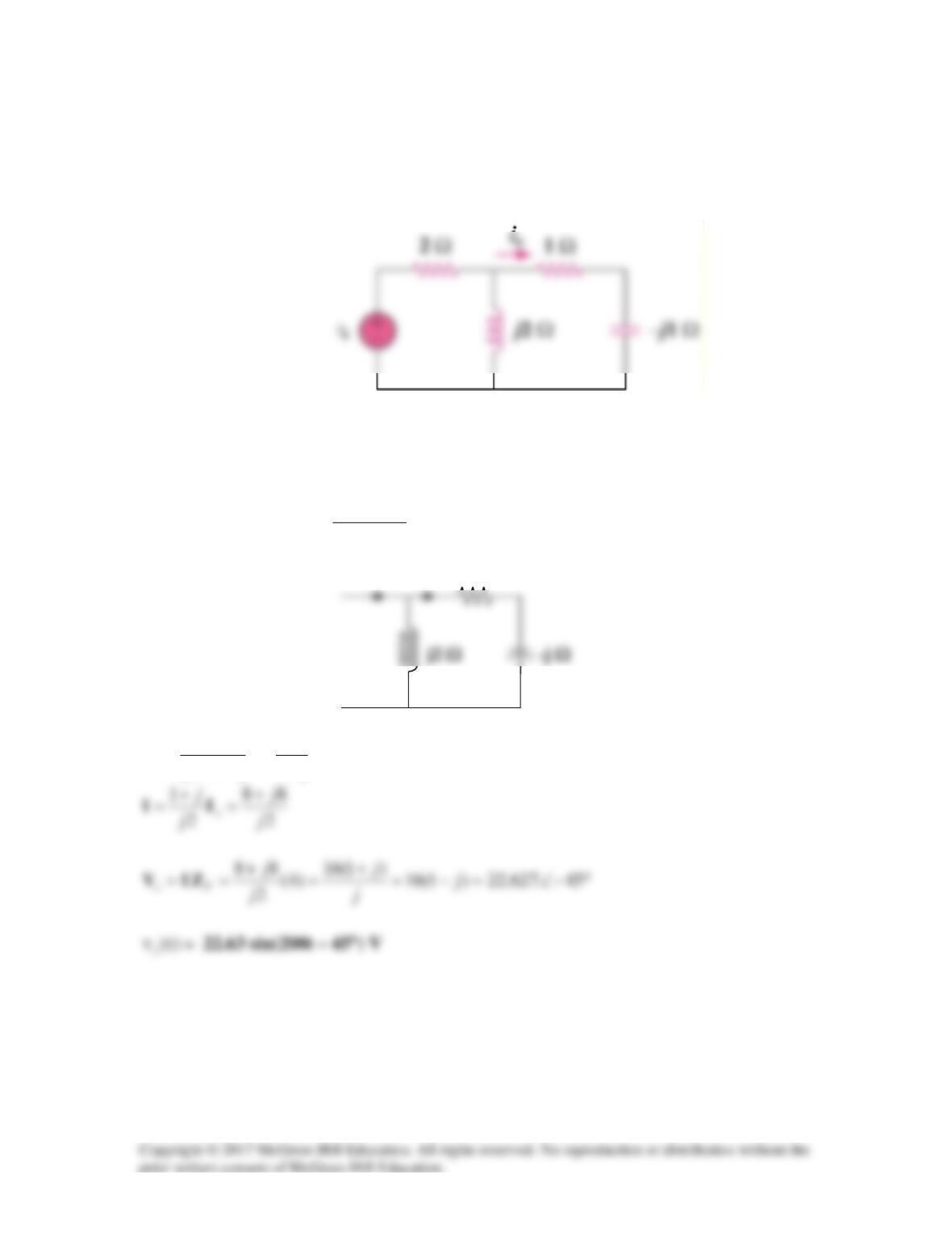
Find v(t) in the RLC circuit of Fig. 9.48.
Figure 9.48
For Prob. 9.41.
Solution
1=ω
,
j)1)(1(jLjH1 ==ω→
Solution 9.42
200=ω
100j–
)1050)(200(j
1
Cj
1
F50 6– =
×
=
ω
→µ
Solution 9.43
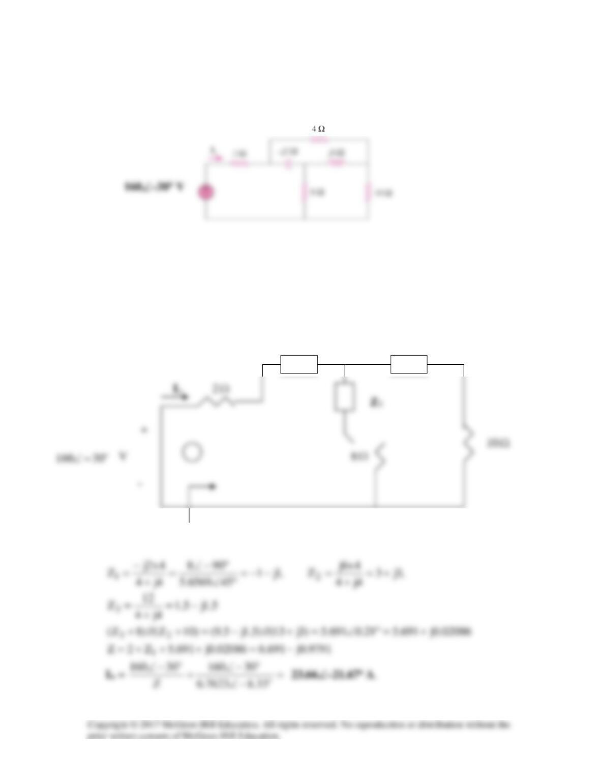
Find current Io in the circuit shown in Fig. 9.50.
Figure 9.50
For Prob. 9.43.
Solution
First we convert the current source into a voltage source (100∠0° V) in series with 20 Ω.
Io
Solution 9.44
Calculate i(t) in the circuit of Fig. 9.51.
Figure 9.51
For Prob. 9.44.
Solution
200=ω
2j)1010)(200(jLjmH10
-3
=×=ω→
Solution 9.45
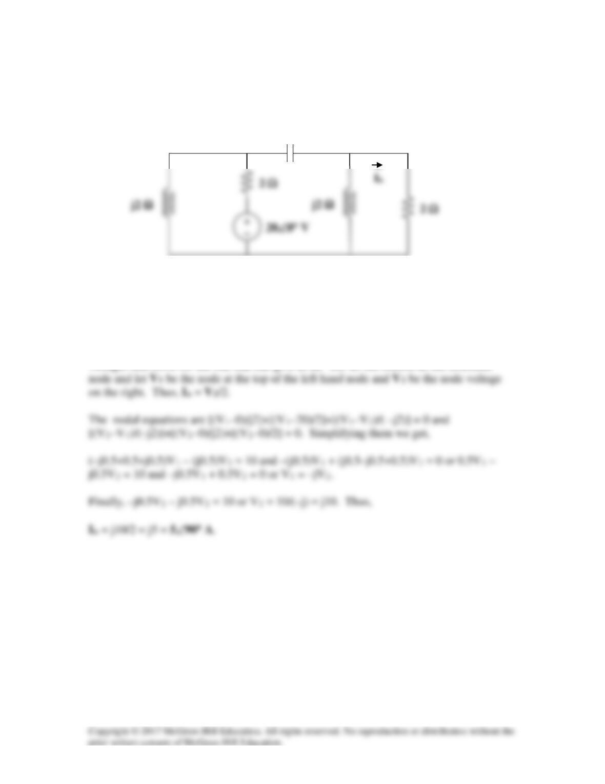
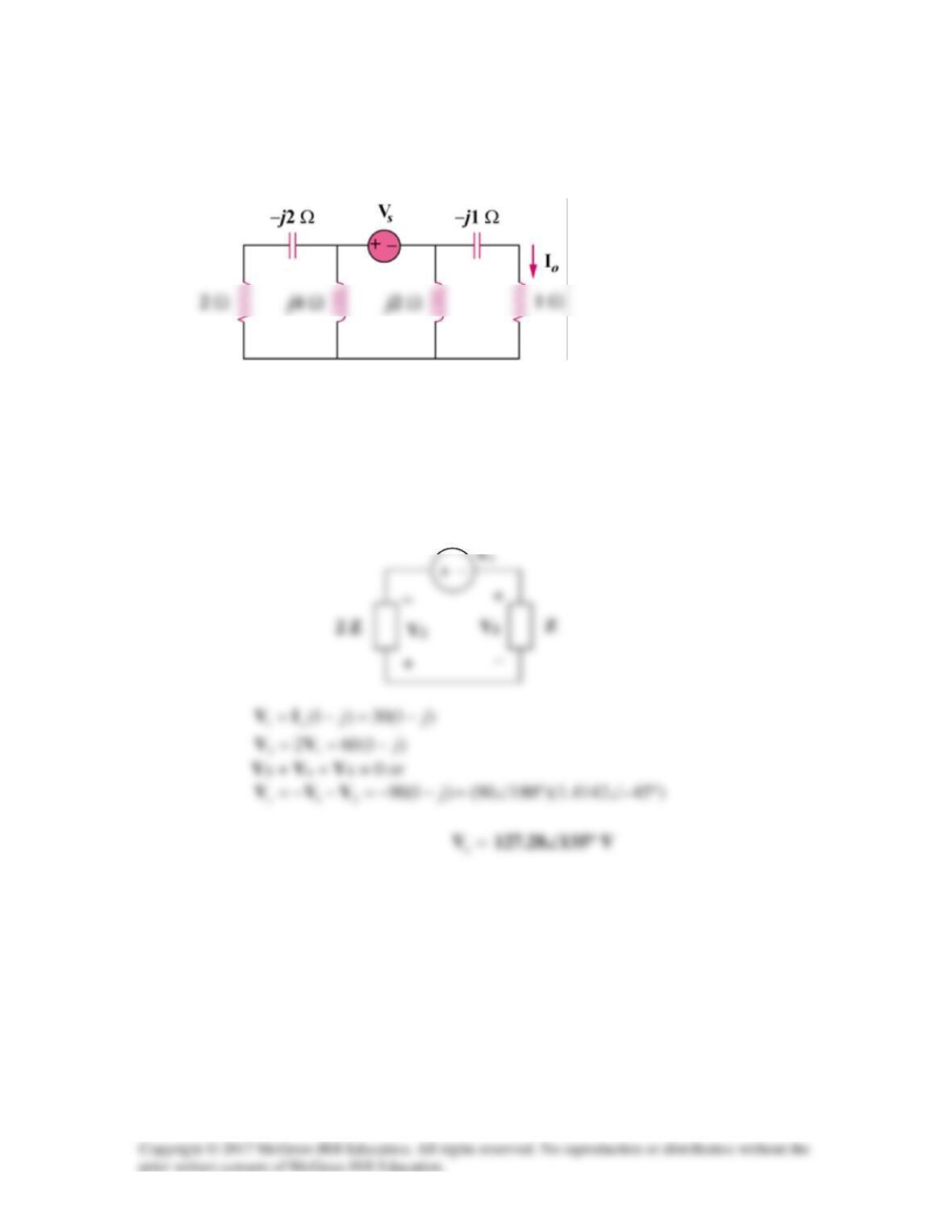
Find current Io in the network of Fig. 9.52.
Figure 9.52
For Prob. 9.45.
Solution
There are different ways to solve this problem. We could identify two unknown node
voltages and solve for the one that can give us Io. So, set the bottom as the reference
–j2 Ω
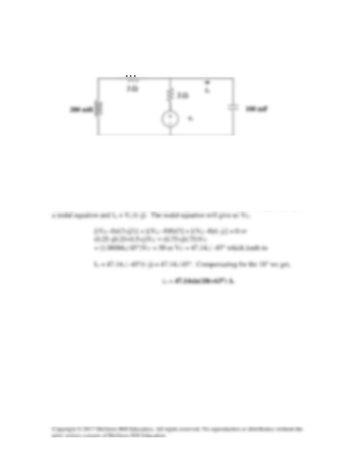
Solution 9.46
If vs = 100sin(10t+18°) V in the circuit in Fig. 9.53, find io.
Figure 9.53
For Prob. 9.46.
Solution
Let Vs = 100∠0° V (we will account for the 18° when we convert Io back into the time
domain). The inductor becomes j2 Ω and the capacitor becomes –j Ω. We can now write
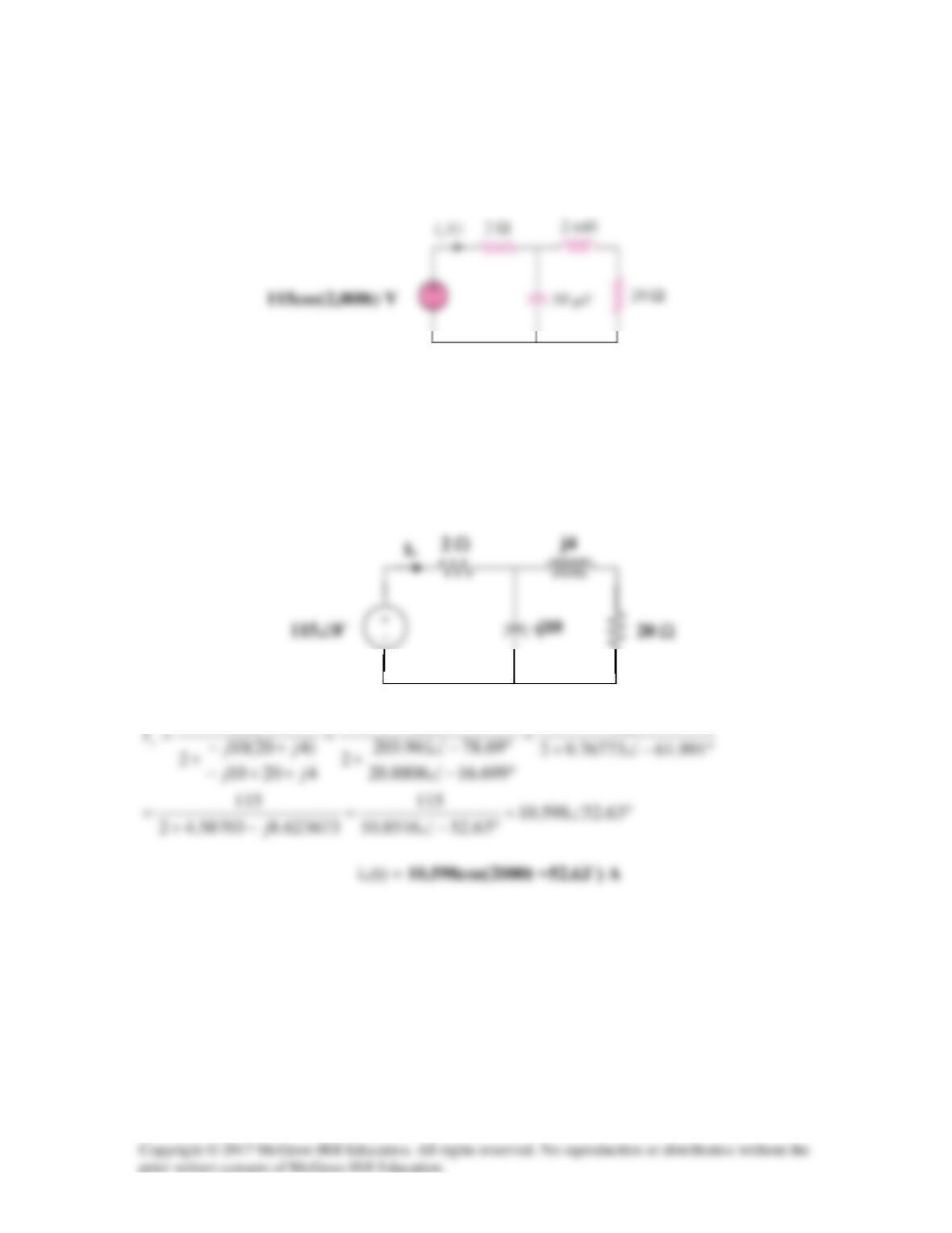
Solution 9.47
In the circuit shown in Fig. 9.54, determine the value of is(t).
Figure 9.54
For Prob. 9.47.
Solution
First, we convert the circuit into the frequency domain.
115
115
115
Solution 9.48
Converting the circuit to the frequency domain, we get:
We can solve this using nodal analysis.
j
V
j
VV
0
2030
0
20
0
10
4020
111
=
−
−
+
−
+
°−∠−
Solution 9.49
Find vs(t) in the circuit of Fig. 9.56 if the current ix through the 1-Ω resistor is
8 sin 200t A.
Figure 9.56
For Prob. 9.49.
Solution
4
j1
)j1)(2j(
2)j1(||2j2
T
=
+
−
+=−+=Z
III j1
2j
j12j
2j
x+
=
−+
=
, where
808 =°∠=
x
I
I
I
x
1 Ω
Solution 9.50
Since ω = 100, the inductor = j100x0.1 = j10 Ω and the capacitor = 1/(j100x10-3)
Using the current dividing rule:
Solution 9.51
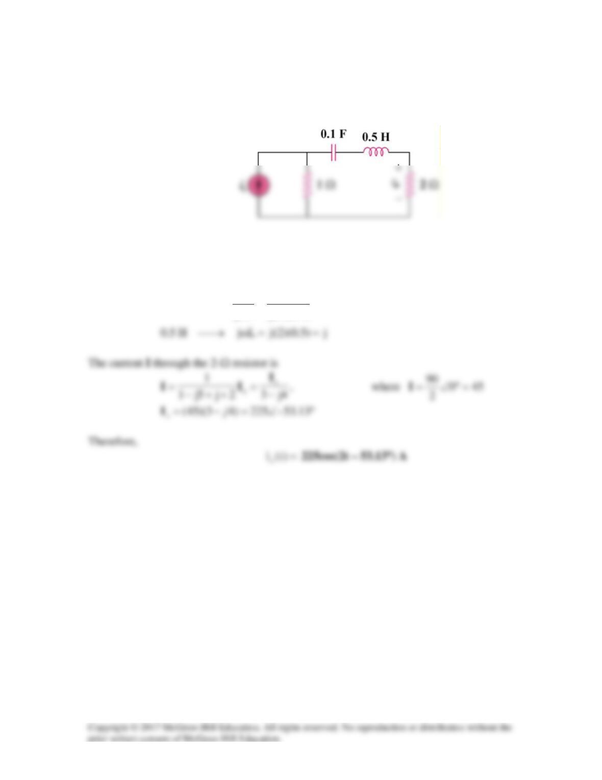
If the voltage vo across the 2–Ω resistor in the circuit of Fig. 9.58 is 90cos(2t) V, obtain is.
Figure 9.58
For Prob. 9.51.
Solution
5j–
)1.0)(2(j
1
Cj
1
F1.0 ==
ω
→
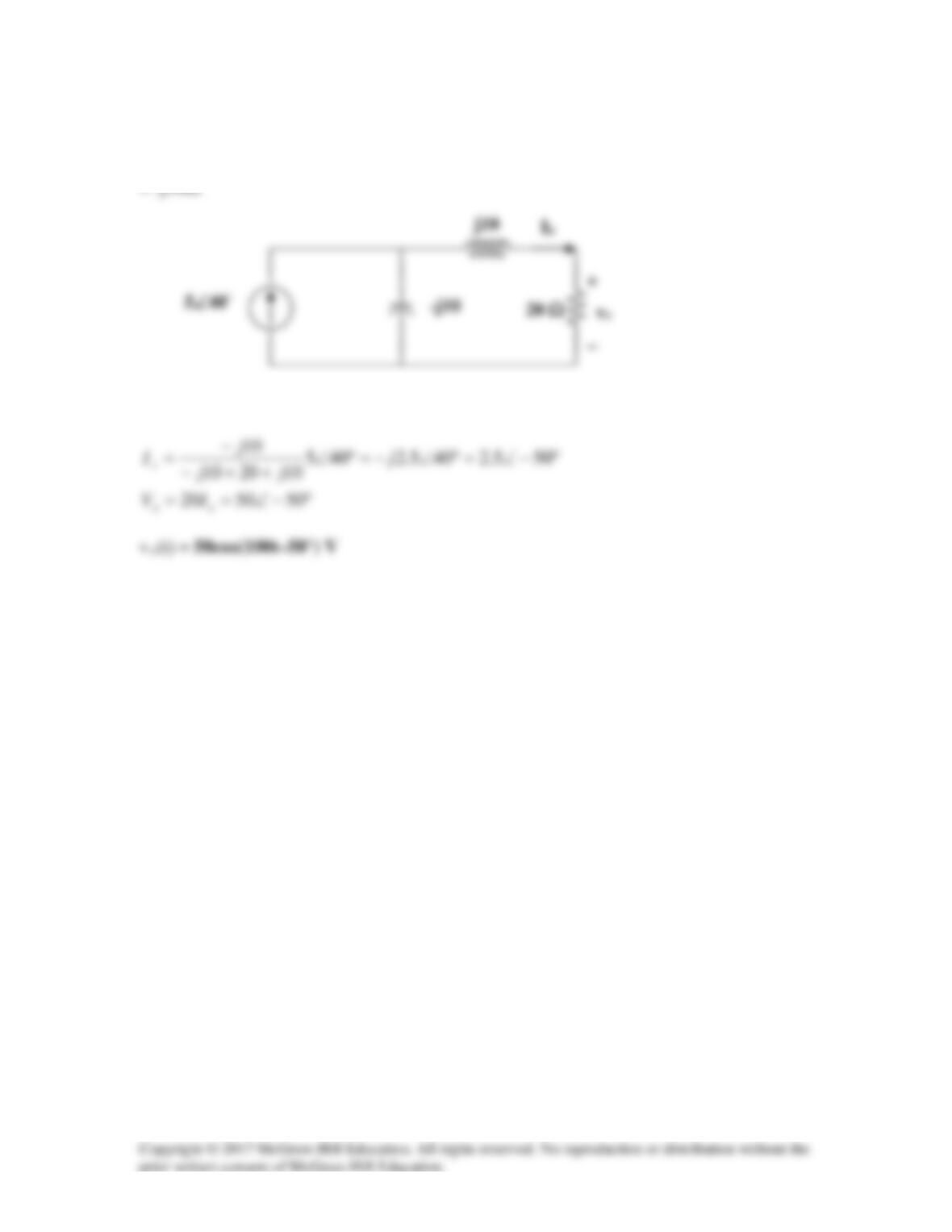
Solution 9.52
If Vo = 8∠30° V in the circuit of Fig. 9.59, find Vs.
Figure 9.59
For Prob. 9.52
Solution
We can treat Vo as the node voltage for the circuit and then write the node equations. We
j5 Ω
10 Ω
−
Solution 9.53
Find I0 in the circuit in Fig. 9.60.
Figure 9.60
For Prob. 9.53.
Solution
Convert the delta to wye subnetwork as shown below.
Z1 Z2
Z
Solution 9.54
In the circuit of Fig. 9.61, find Vs if Io = 30∠0° A.
Figure 9.61
For Prob. 9.54.
Solution
Since the left portion of the circuit is twice as large as the right portion, the equivalent
circuit is shown below.
Solution 9.55
-j0.5
8j
4
8j
o
1
=== V
I
I
I
1
12 Ω
Z
Solution 9.56
11
Solution 9.57
2H2 jLj =→
ω
Solution 9.58
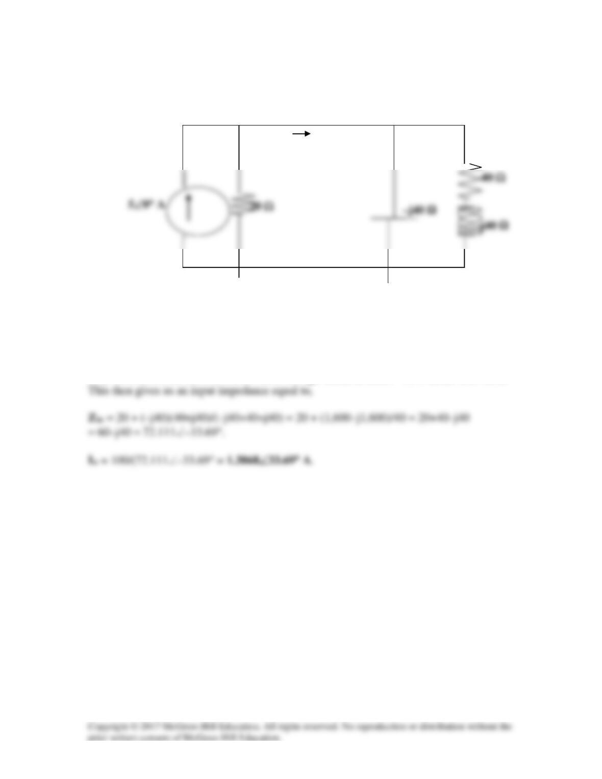
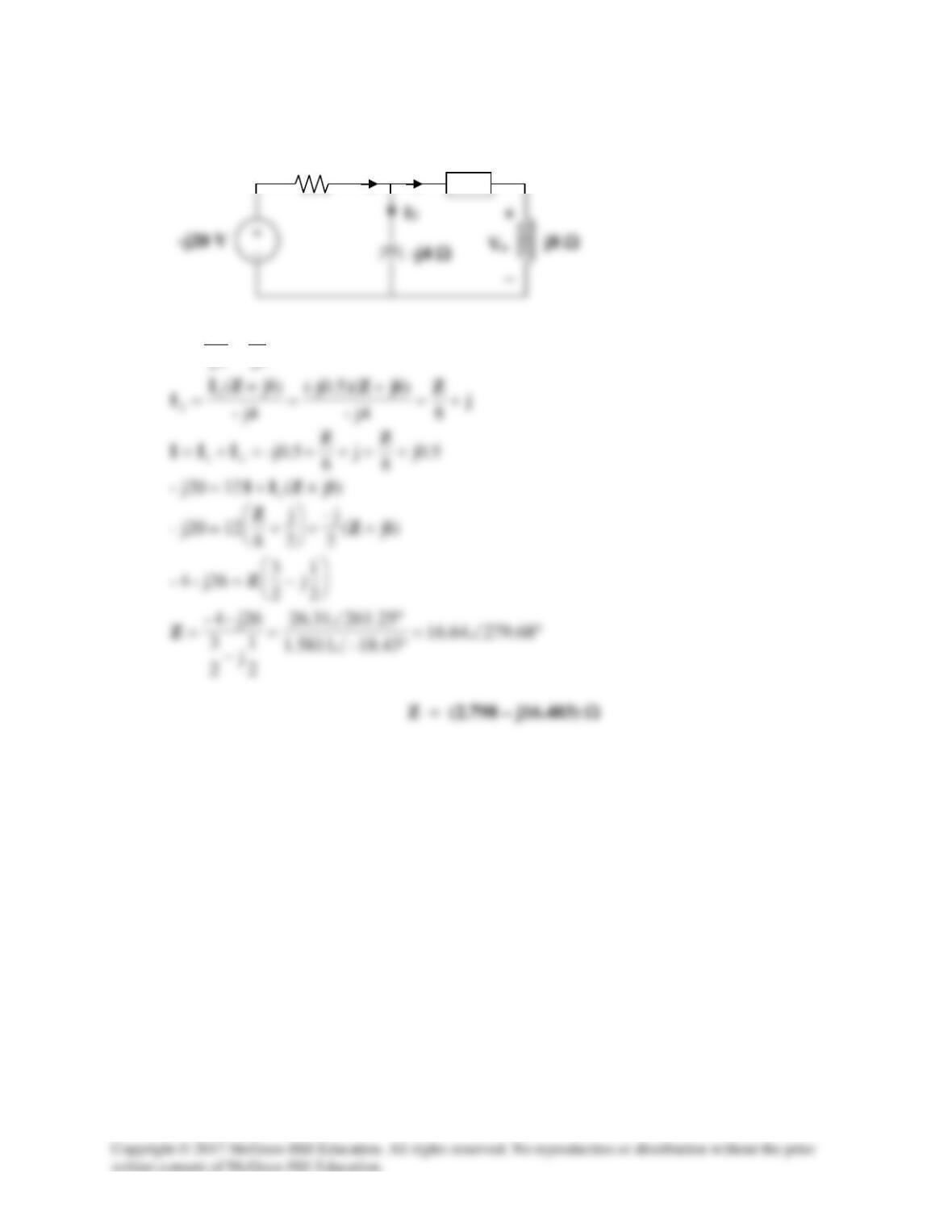
Using Fig. 9.65, design a problem to help other students to better understand impedance
combinations.
Problem
At
ω
= 50 rad/s, determine Zin for each of the circuits in Fig. 9.65.
Figure 9.65
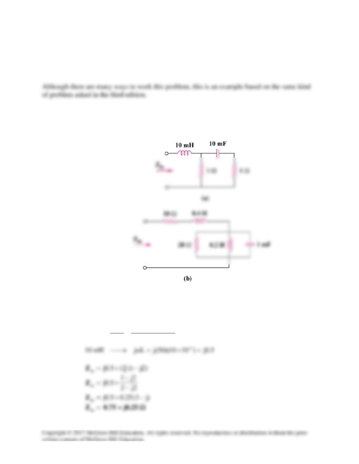
Solution
(a)
2j–
)1010)(50(j
1
Cj
1
mF10 3– =
×
=
ω
→
(b)
20j)4.0)(50(jLjH4.0 ==ω→
10j)2.0)(50(jLjH2.0 ==ω→