Solution 6.1

Solution 6.2
Solution 6.3
Design a problem to help other students to better understand how capacitors work.
Problem
In 5 s, the voltage across a 40–mF capacitor changes from 160 V to 220 V. Calculate the average
current through the capacitor.
Solution

Solution 6.4
A voltage across a capacitor is equal to [2–2 cos(4t)] V and the current flowing through it
Solution
Starting with iC = CdvC/dt and vC = [2–2 cos(4t)] V and that iC = 2sin(4t) µA,
Solution 6.5
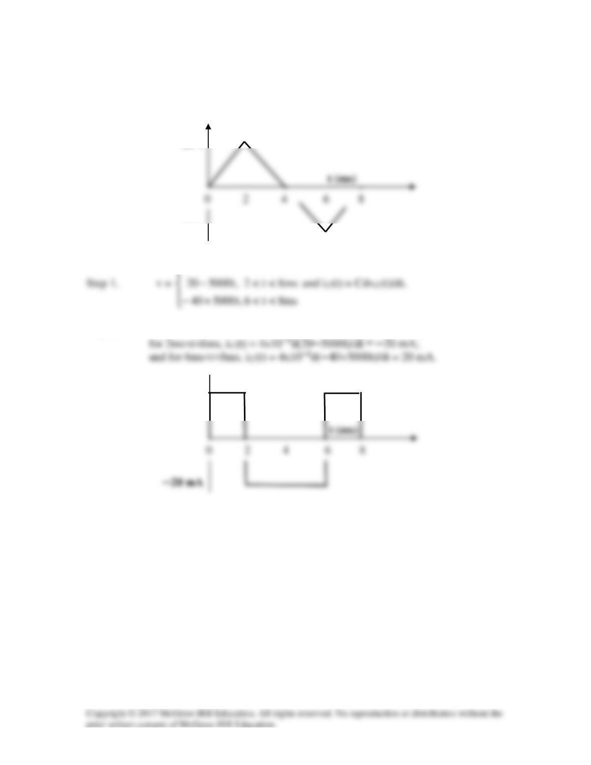
The voltage across a 4–µF capacitor is shown below. Find the current waveform.
<<
ms2t0
,t5000
Step 2. For 0<t<2ms, iC(t) = 4×10─6d(5000t)/dt = 20 mA;
─10 V
10 V
20 mA
Solution 6.6
6
1055 −
== x
dv
Ci
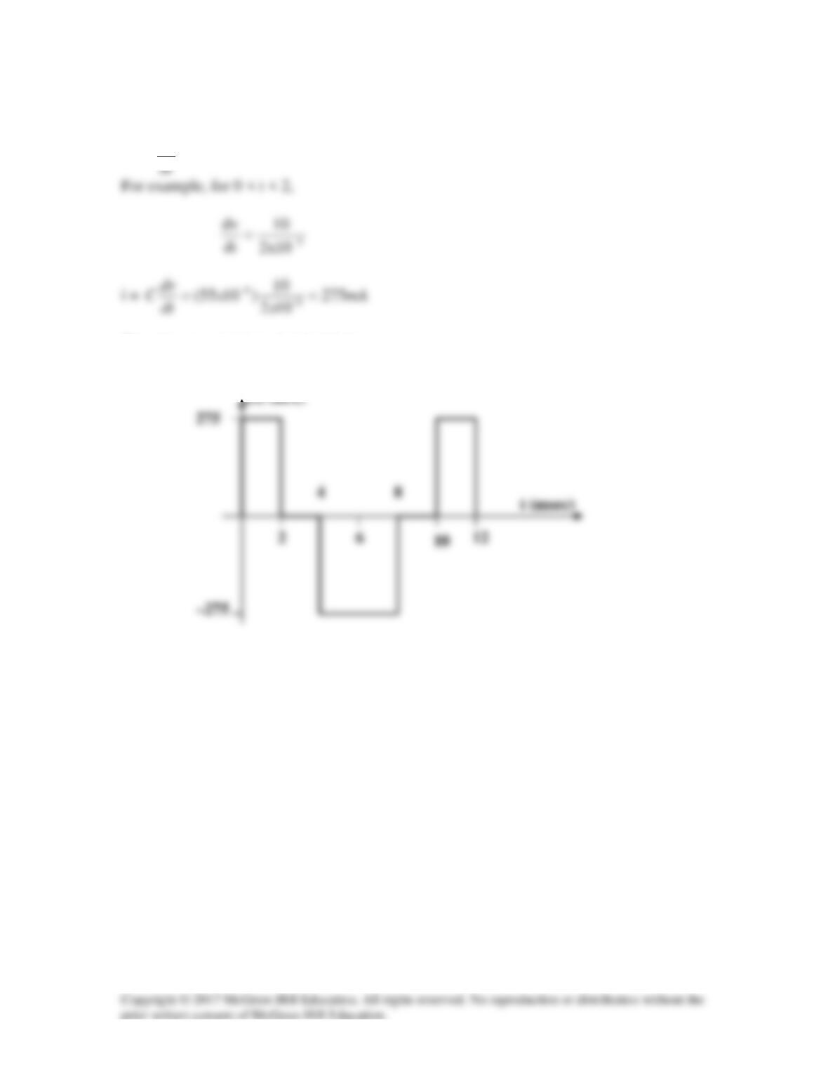
times the slope of the waveform.
Thus the current i(t) is sketched below.
Solution 6.7
Solution 6.8
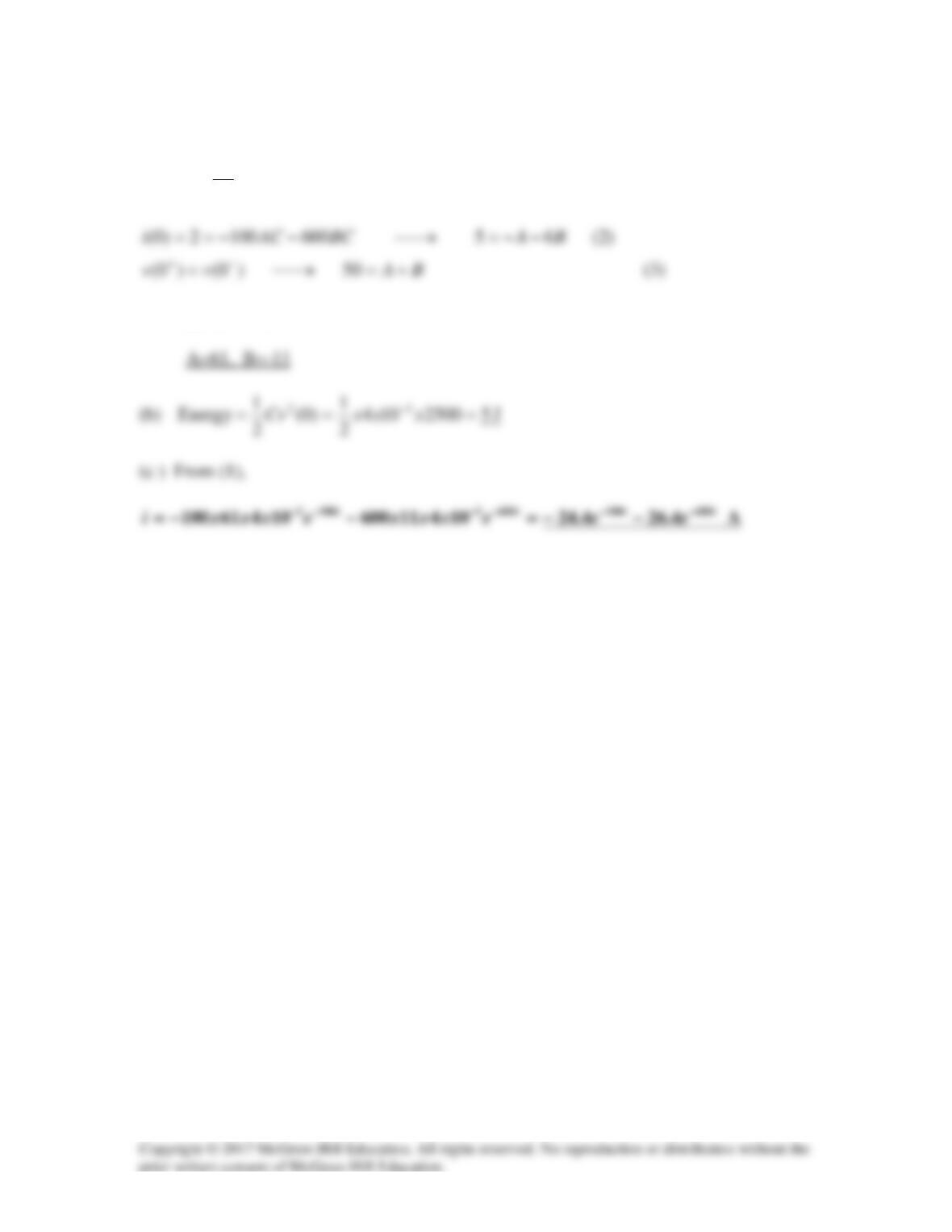
(a)
tt
BCeACe
dt
dv
Ci
600100
600100
−−
−−==
(1)
Solving (2) and (3) leads to

Solution 6.9
v(t) =
( ) ( )
∫−− +=+−
t
o
t
0
tt Vet120dte16
21
1
= 12(t + e-t) – 12
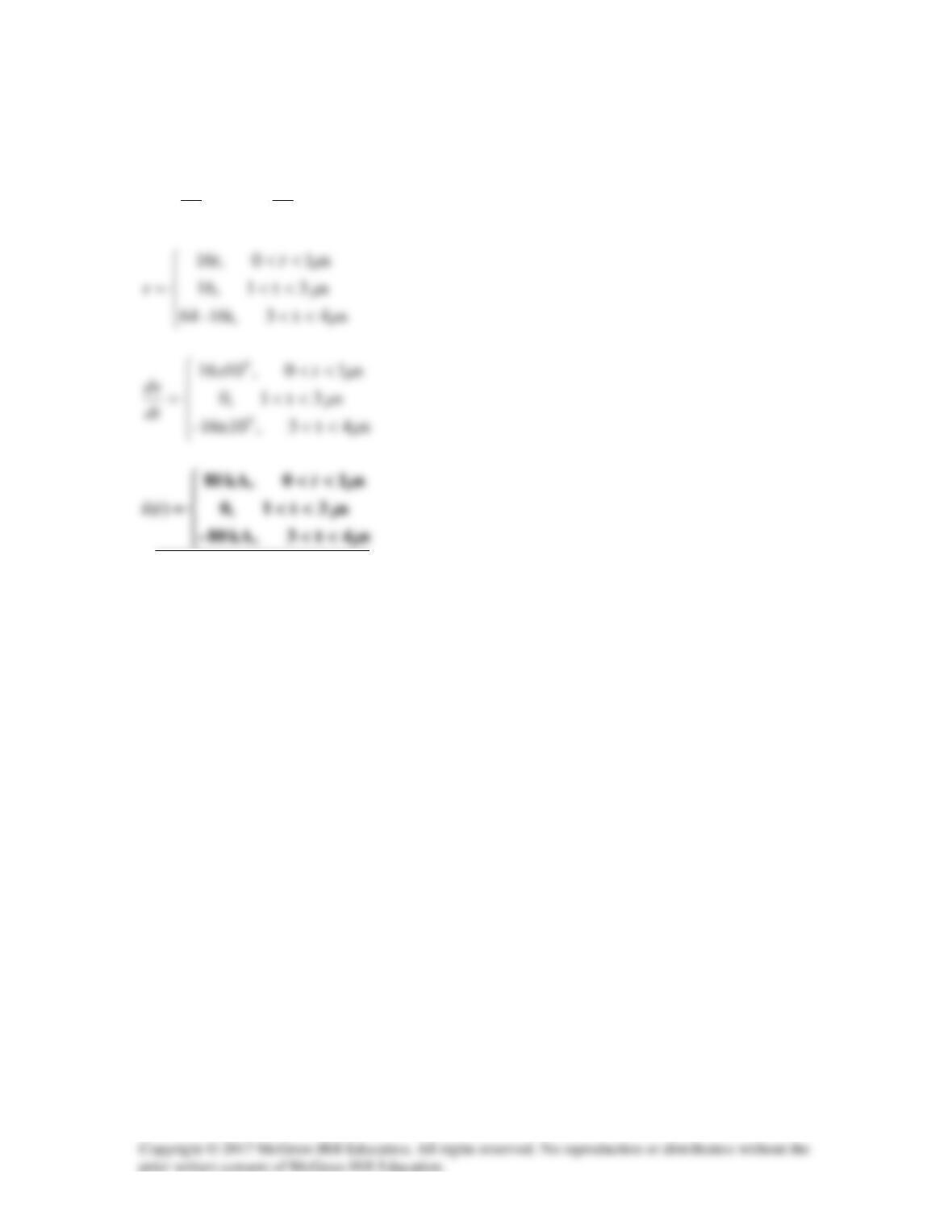
Solution 6.10
dt
dv
x
dt
dv
Ci
3
105
−
==
Solution 6.11
−
= +=+
∫∫
3
00
11
(0) 10 ( )
4 10
tt
v idt v i t dt
Cx
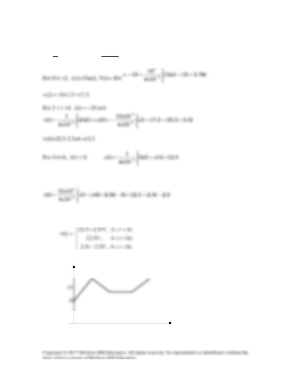
For 6<t<8, i(t) = 10 mA
Hence,
10 3.75 , 0 2
tV t s
+ <<
which is sketched below.
v(t)
20
5
t (s)
0 2 4 6 8

Solution 6.12
A voltage of 45e–2000t V appears across a parallel combination of a 100-mF capacitor and
a 12–Ω resistor. Calculate the power absorbed by the parallel combination.
Solution
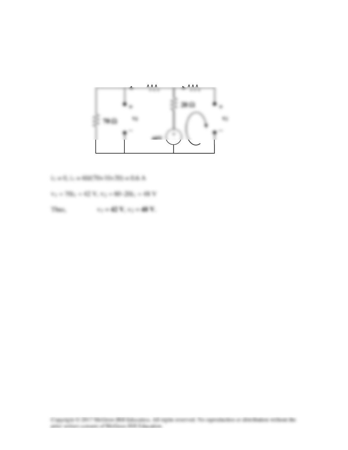
Solution 6.13
Under dc conditions, the circuit becomes that shown below:
10 Ω
i1
60V
−
50 Ω
i2

Solution 6.14
20 pF is in series with 60pF = 20*60/80=15 pF
Solution 6.15
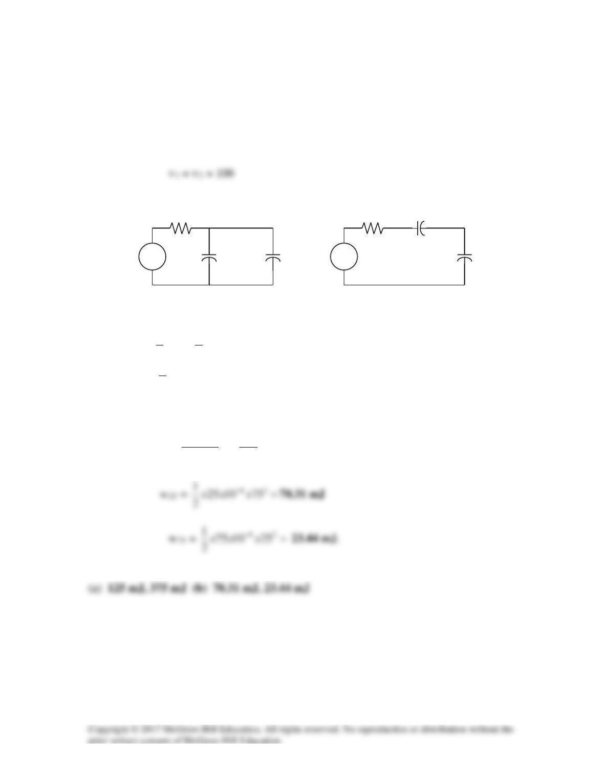
Arranging the capacitors in parallel results in circuit shown in Fig. (1) (It should be noted
that the resistors are in the circuits only to limit the current surge as the capacitors charge.
Once the capacitors are charged the current through the resistors are obviously equal to
zero.):
w20 =
==
−262
1001025
2
1
2
1xxxCv
125 mJ
w30 =
=
−26 1001075
2
1xxx
375 mJ
(b) Arranging the capacitors in series results in the circuit shown in Fig. (2):
==
+
=100
100
75
21
2
1xV
CC
C
v
75 V, v2 = 25 V
(1)
C2
+
v2
−
100V
+
−
+
v1
−
C1
+ −
v1
(2)
C2
+
v2
−
100V
+
−
C1
R
R
Solution 6.16
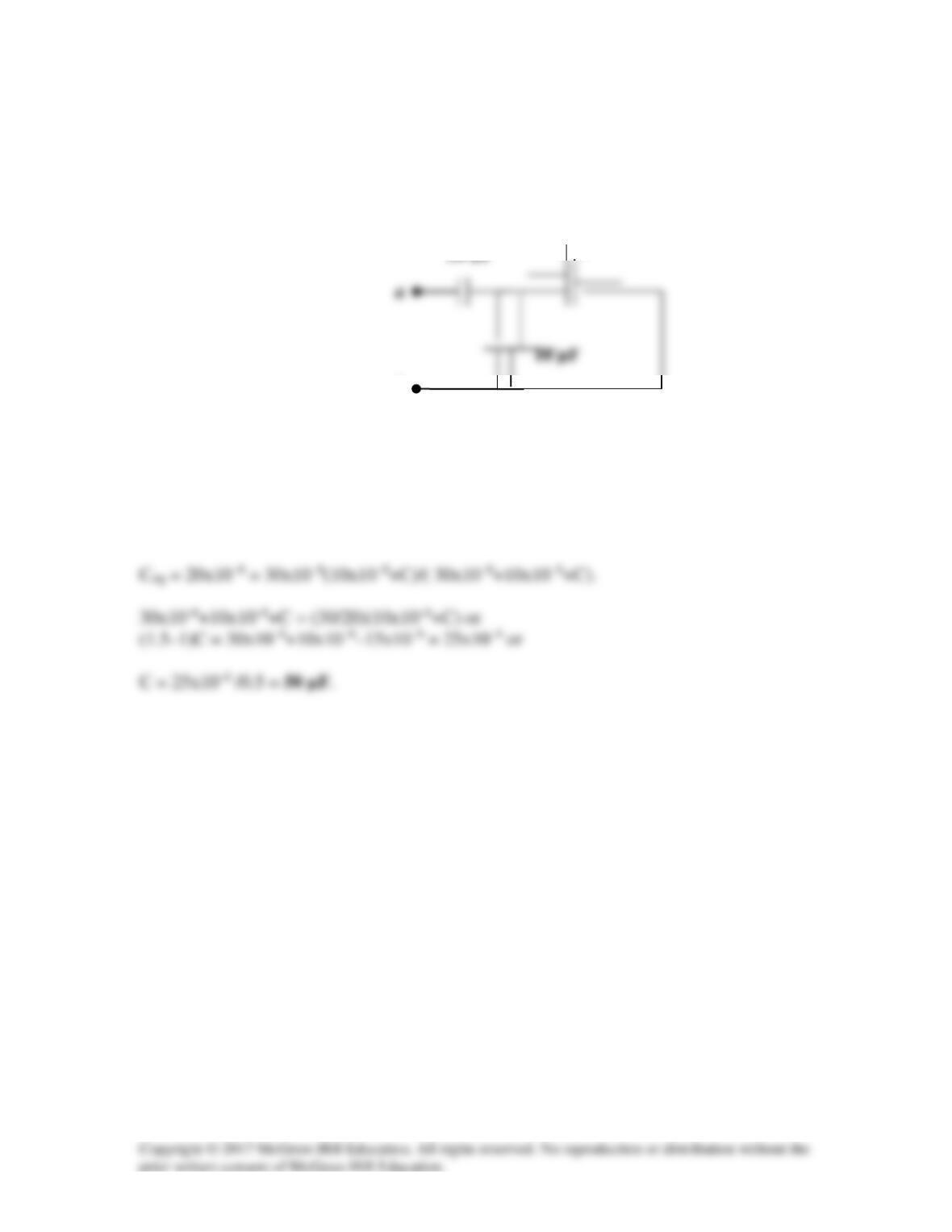
The equivalent capacitance at terminals a–b in the circuit in Fig. 6.50 is 20 µF. Calculate
the value of C.
Figure 6.50
For Prob. 6.16.
Solution
The capacitance looking into terminals a and b is equal to,
b
C
Solution 6.17
(a) 4F in series with 12F = 4 x 12/(16) = 3F
(c)
(d) 3F in series with 6F = (3 x 6)/9 = 2F
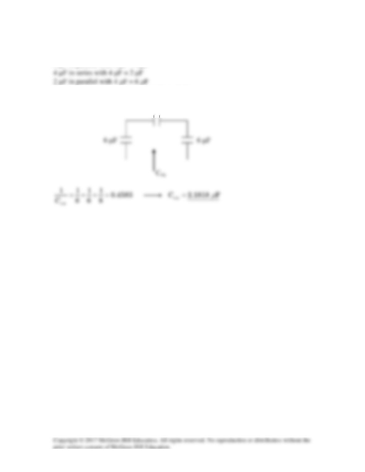
Solution 6.18
4 µF in parallel with 4 µF = 8µF
Hence, the circuit is reduced to that shown below.
8µF
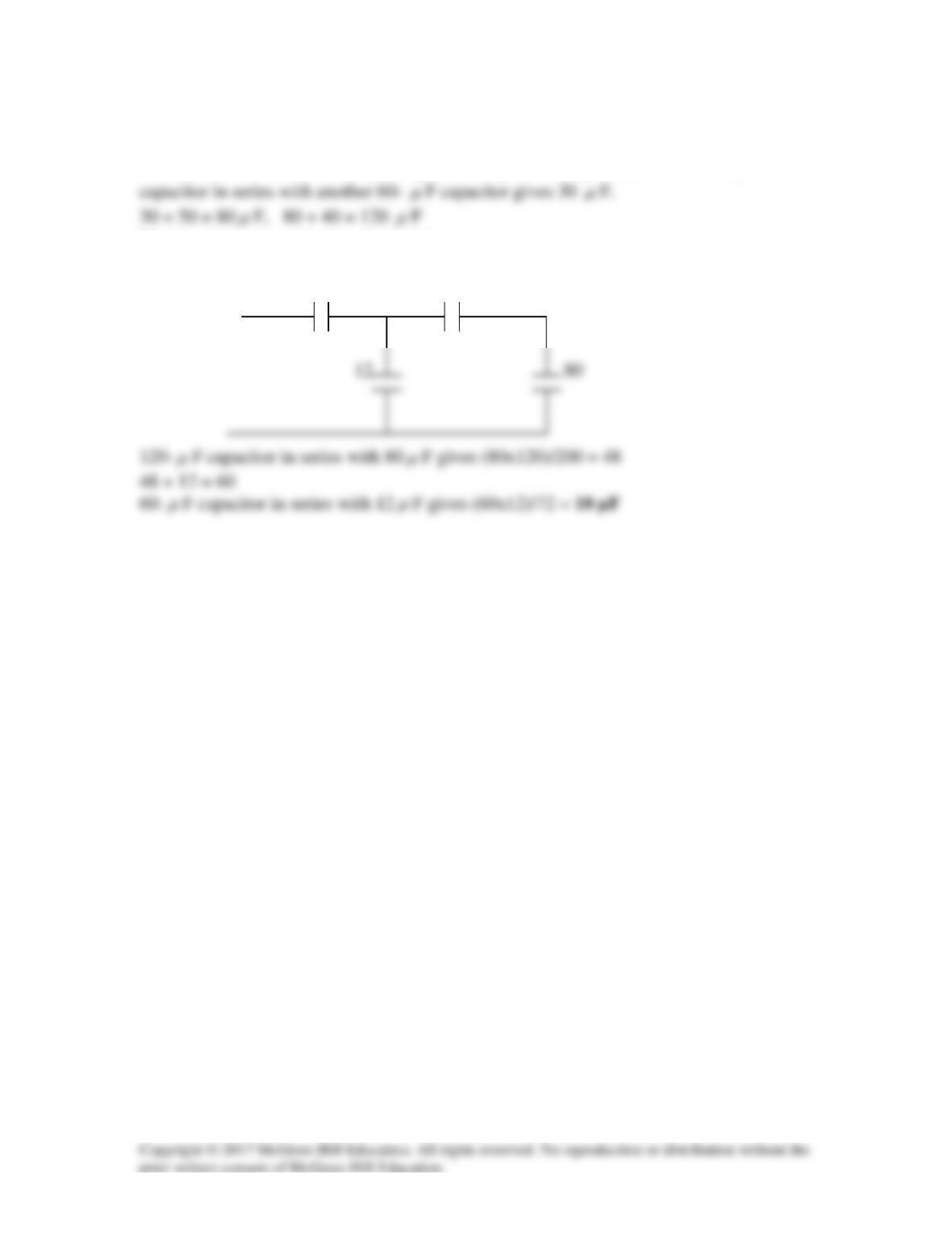
Solution 6.19
We combine 10-, 20-, and 30-
µ
F capacitors in parallel to get 60
µ
F. The 60 –
µ
F
µ
µ
µ
µ
The circuit is reduced to that shown below.
12 120
µ
µ
µ
µ
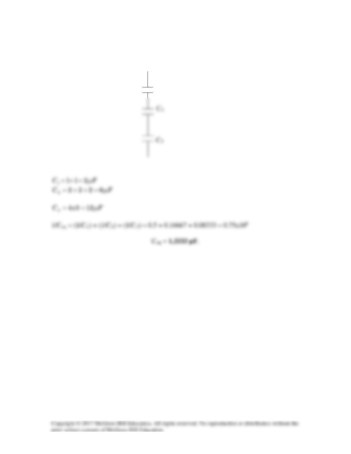
Solution 6.20
Consider the circuit shown below.
C1