indicates that
0
2=I
and that
Solution 19.65
The network consists of two two-ports in series. It is better to work with z parameters
and then convert to y parameters. It is obvious that the upper 1 Ω resistor is shorted out
by the top circuit so we are essentially left with 2 Ω connected to 3 Ω. This then
produces the Z parameters
ΩΩ
35
Solution 19.66
Since we have two two–ports in series, it is better to convert the given y parameters to z
parameters.
–
12
22
yy
But, at the input port,
and at the output port,
From (2) and (4),
Substituting (1) and (5) into (3),
From (4) and (6),
Solution 19.67
We first the y parameters, To find y11 and y21 consider the circuit below.
I1 30 Ω 40 Ω I2
By current division,
To find y22 and y12 consider the circuit below.
I1 30 Ω 40 Ω
I2
2
By current division,
1
For three copies cascaded in parallel, we can use MATLAB.
>> Y=[1/38,-1/190;-1/190,2/95]
>> Y3=3*Y
Y3 =
Solution 19.68
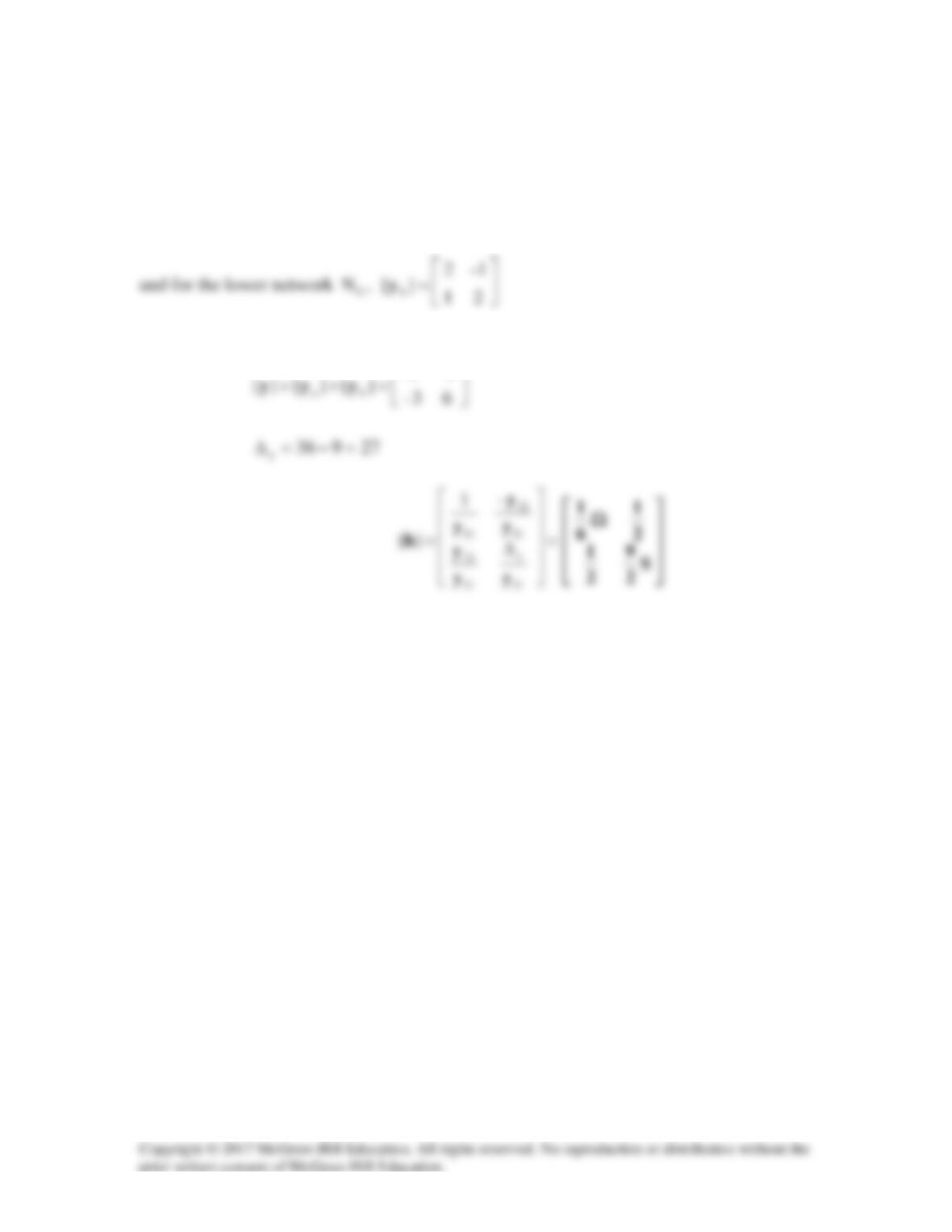
For the upper network a
N
,
=42–
2–4
][
a
y
N
For the overall network,
3–6
Solution 19.69
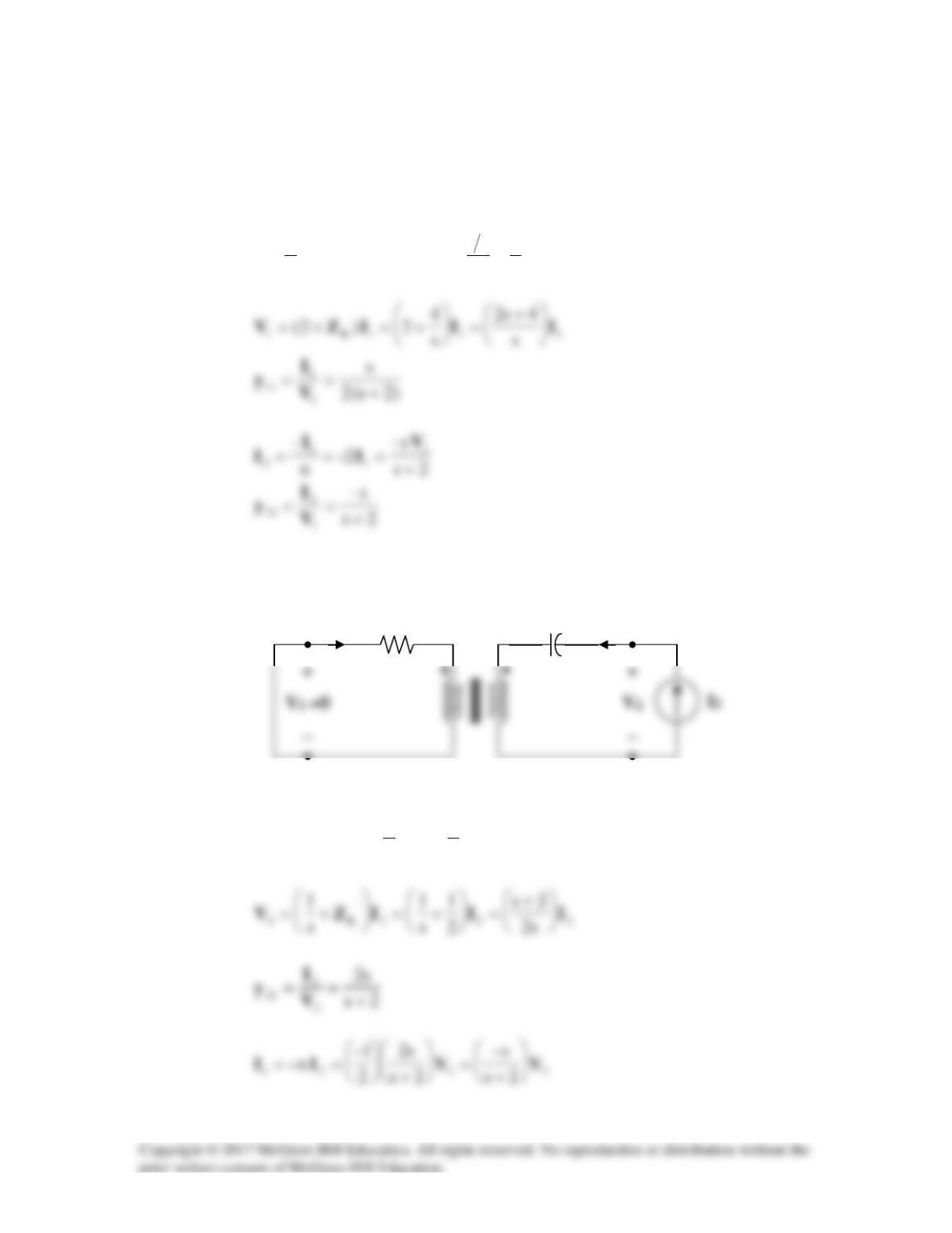
We first determine the y parameters for the upper network
a
N
.
To get
11
y
and
21
y
, consider the circuit in Fig. (a).
2
1
n=,
s
4
n
s1
2
R==Z
To get
22
y
and
12
y
, consider the circuit in Fig. (b).
2
1
)2(
4
1
)2)(n(
2
‘
R
=
==Z
2 : 1
1/s
2 Ω
(b)
(a)
I1
I2
2s
s–
2
1
12
+
== V
I
y
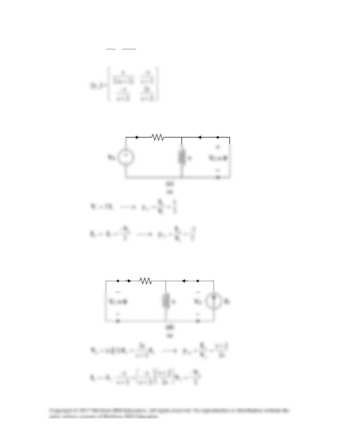
For the lower network b
N
, we obtain
11
y
and
21
y
by referring to the network in Fig. (c).
To get
22
y
and
12
y
, refer to the circuit in Fig. (d).
2
I1
I2
2
I1
I2
2
1–
2
1
12
== V
I
y
Solution 19.70
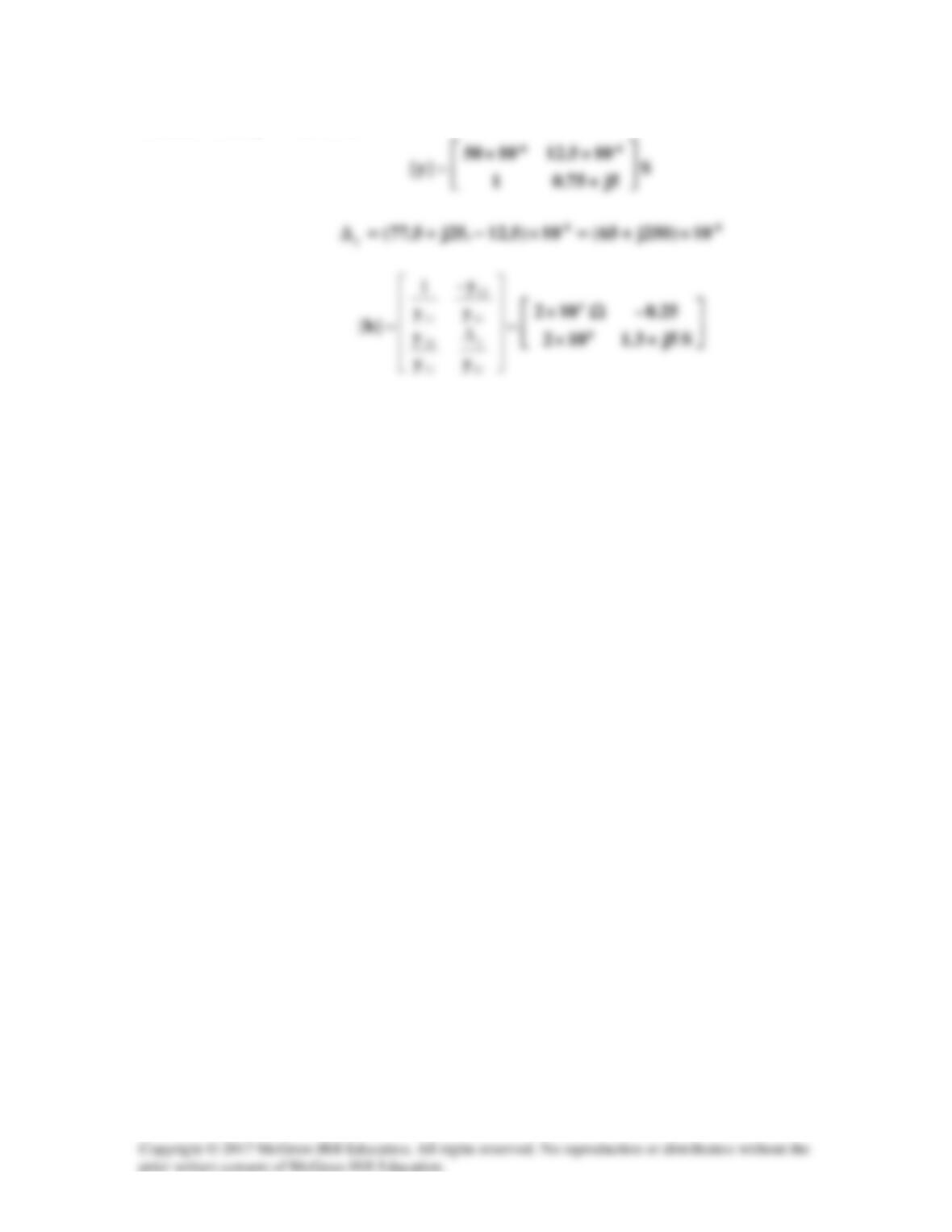
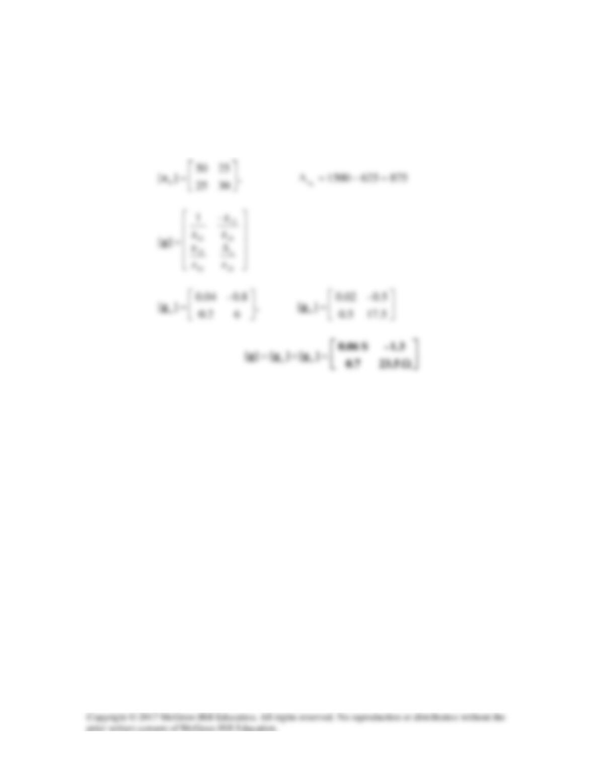
We may obtain the g parameters from the given z parameters.
=105
2025
][
a
z
,
150100250
a
z=−=∆
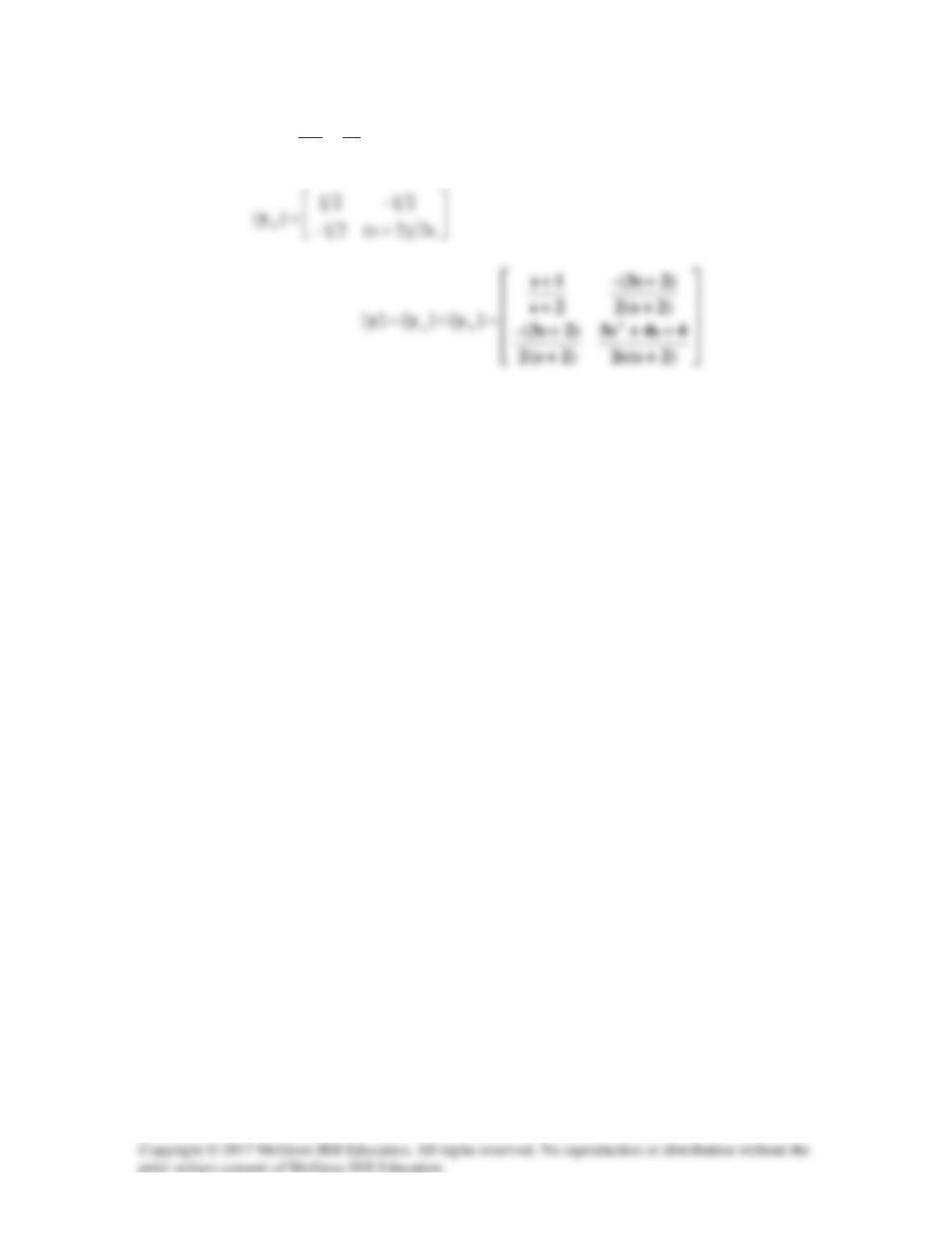
b
z
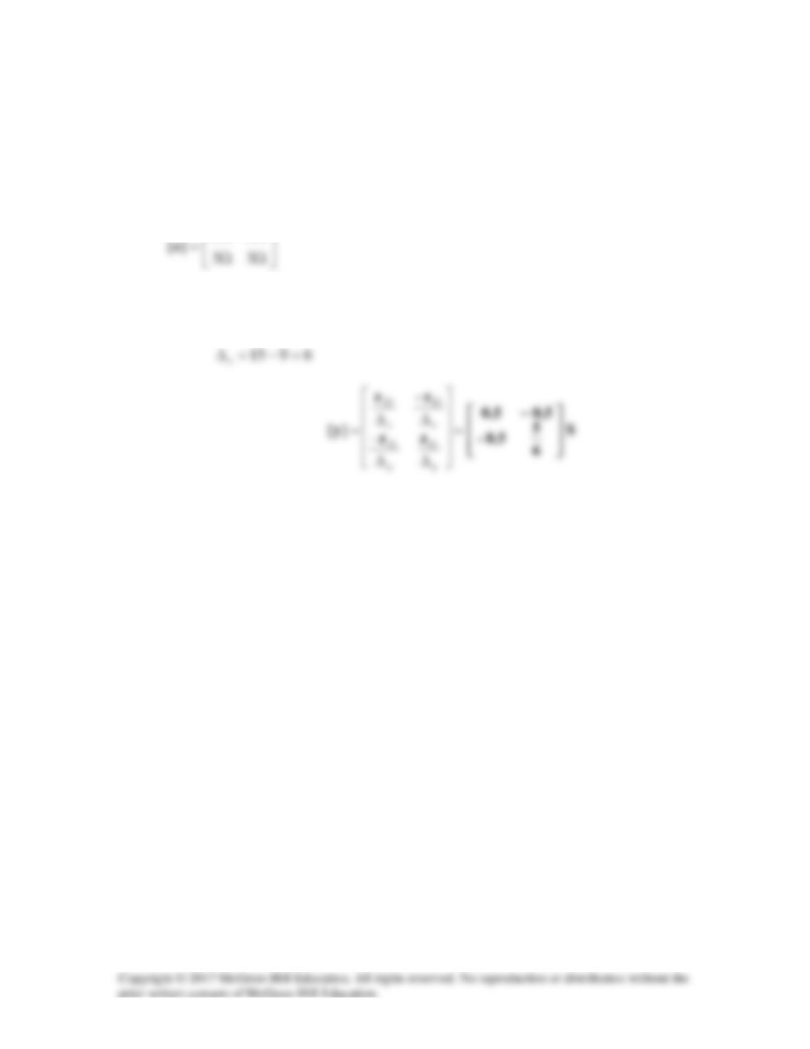
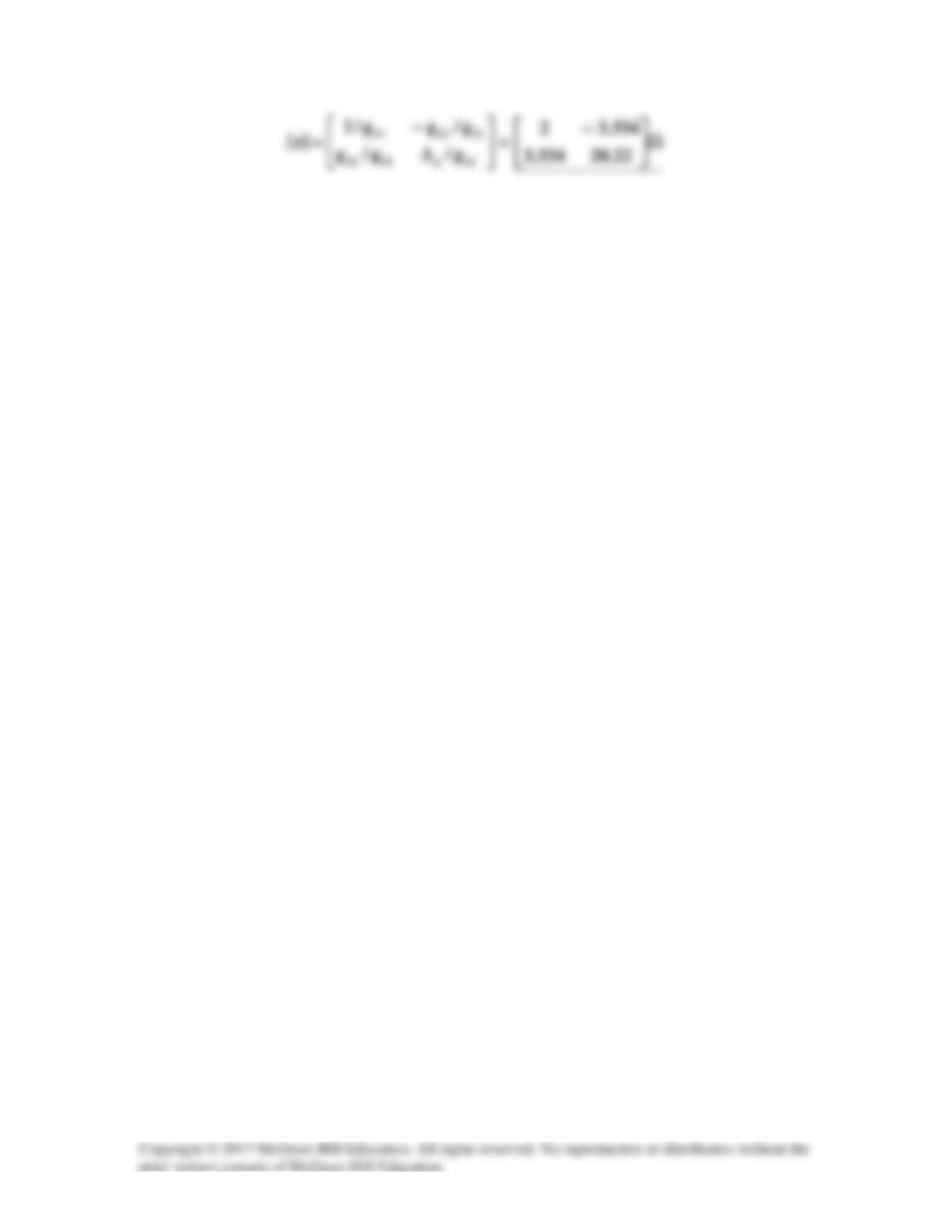
Solution 19.71
This is a parallel-series connection of two two-ports. We need to add their g parameters
together and obtain z parameters from there.
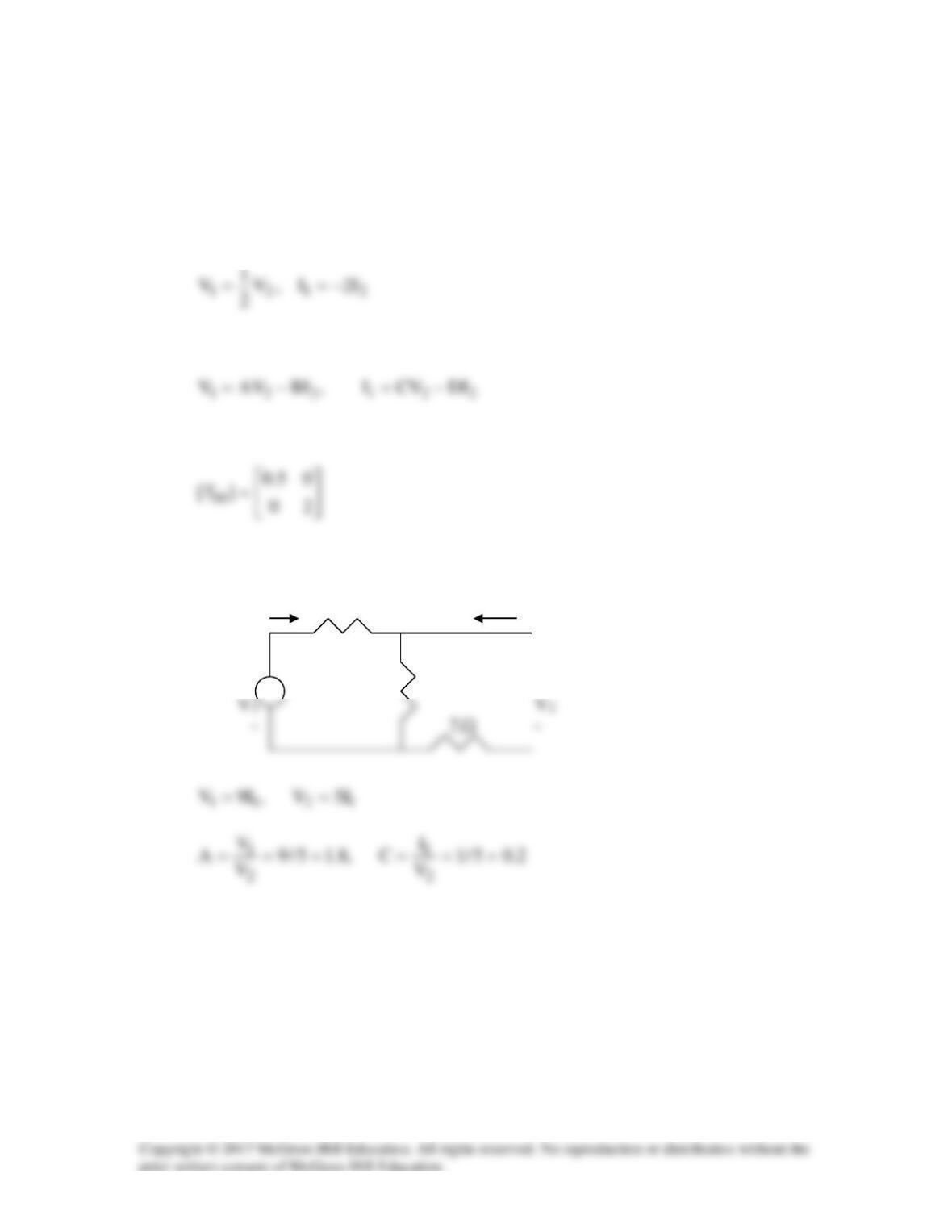
For the transformer,
Comparing this with
shows that
To get A and C for Tb2 , consider the circuit below.
I1 4
Ω
I2 =0
+ +
5
Ω
Ω
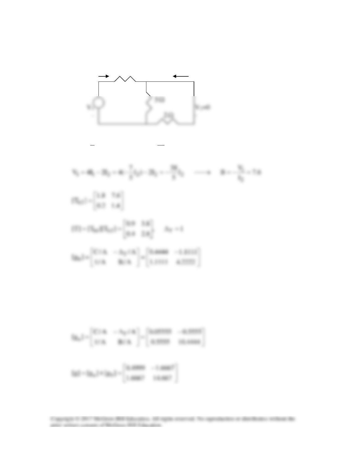
We obtain B and D by looking at the circuit below.
I1 4
Ω
I2 =0
+ +
Ω
Ω
4.15/7
I
I
DI
7
5
I
2
1
12
==−=→−=
From Prob. 19.52,
=6.11.0
8.188.1
]T[ a
Thus,
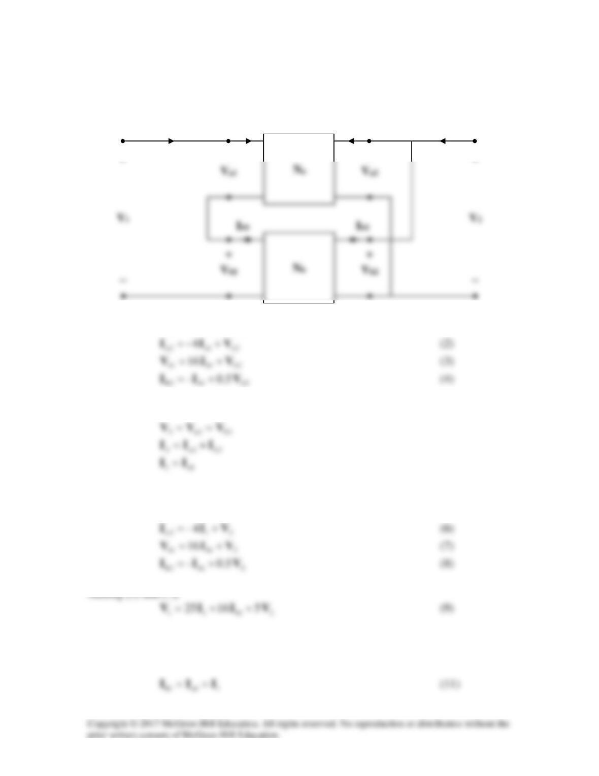
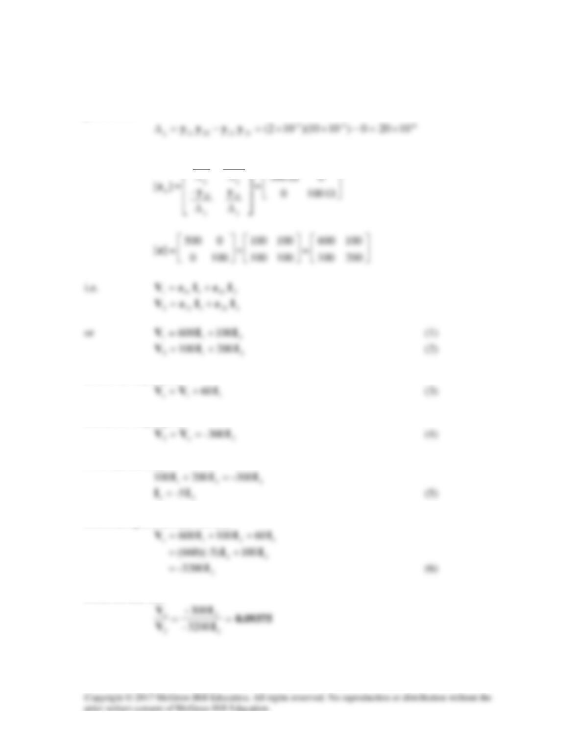
Solution 19.72
Consider the network shown below.
2a1a1a
425 VIV +=
(1)
2bb12b
1b1a1 VVV +=
Now, rewrite (1) to (4) in terms of
1
I
and
2
V
211a
425 VIV +=
(5)
Adding (6) and (8),
21b12 5.14– VIII +−=
(10)
I1
I2
+
+
Ib2
+
Ib1
+
Ia2
+
Ia1
+
Because the two networks
a
N
and
b
N
are independent,
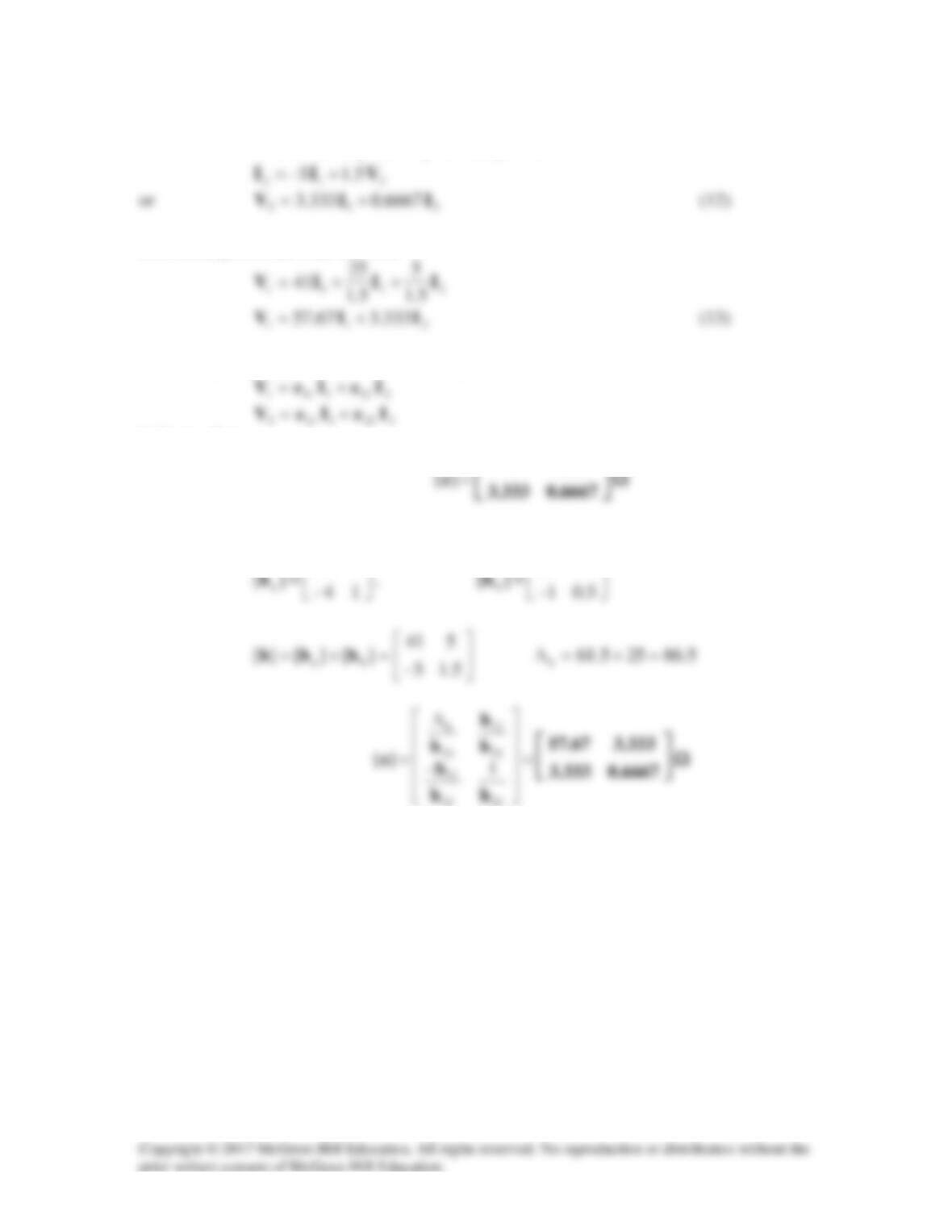
Substituting (11) and (12) into (9),
Comparing (12) and (13) with the following equations
indicates that
333.367.57
Alternatively,
425
116
as obtained previously.
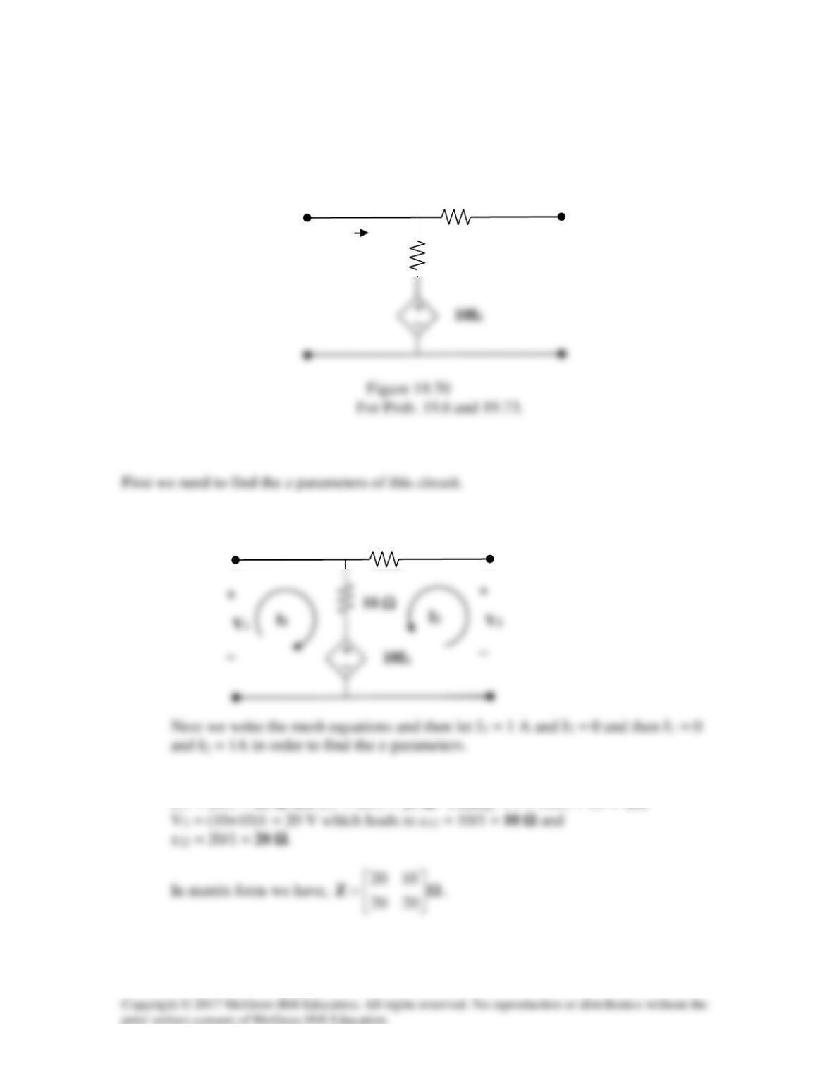
Solution 19.73
Three copies of the circuit shown in Fig. 19.70, are connected in cascade. Determine the
z parameters.
Solution
Step 1. First we label the circuit so that we can find the z–parameters.
10 Ω
Step 2. V1 = 10×1 + 10×1 = 20 V and V2 = 10×1 + 10×1 = 20 V which leads to
z11 = 20/1 = 20 Ω and z21 = 20/1 = 20 Ω. Finally, V1 = 10×1 = 10 V and
I1
10 Ω
10 Ω
10 Ω
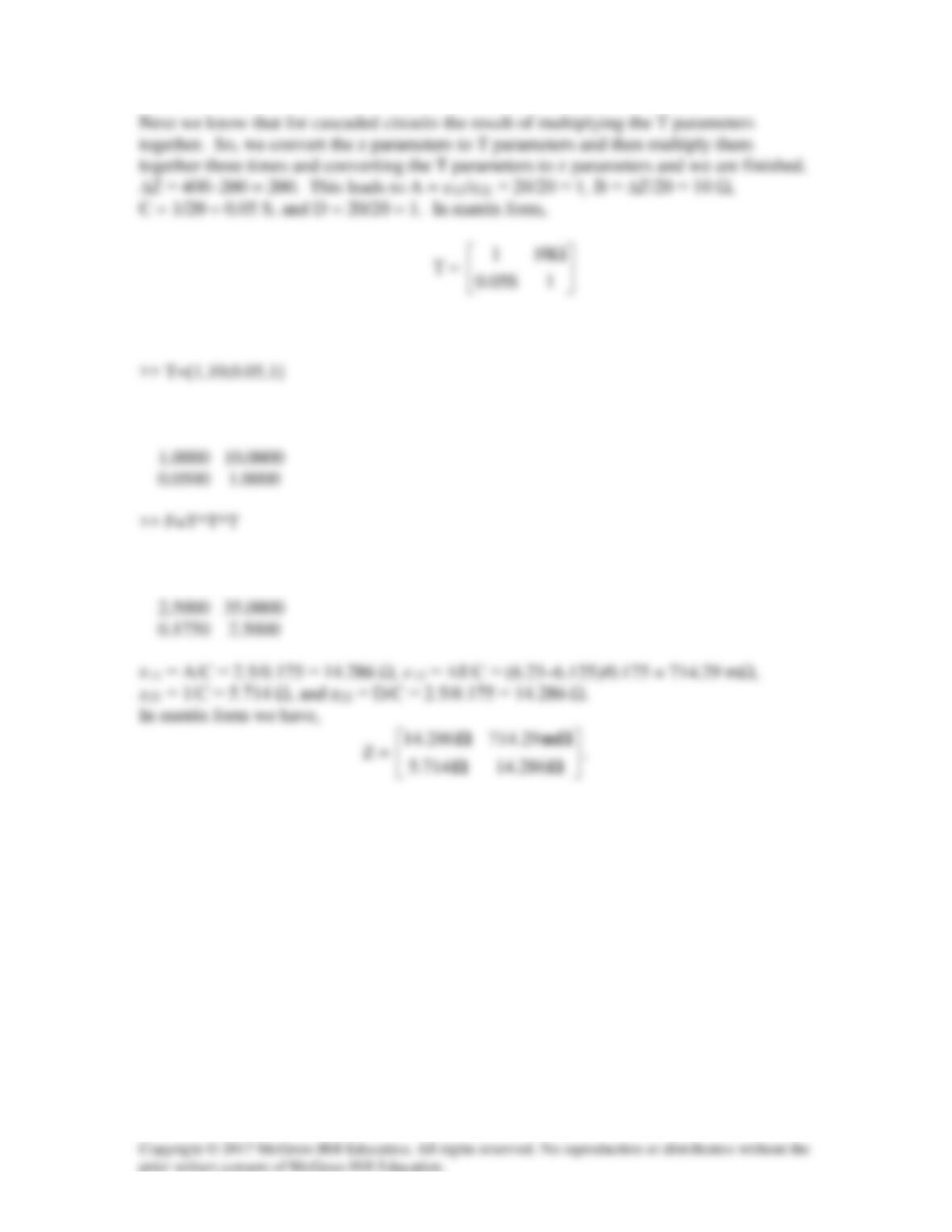
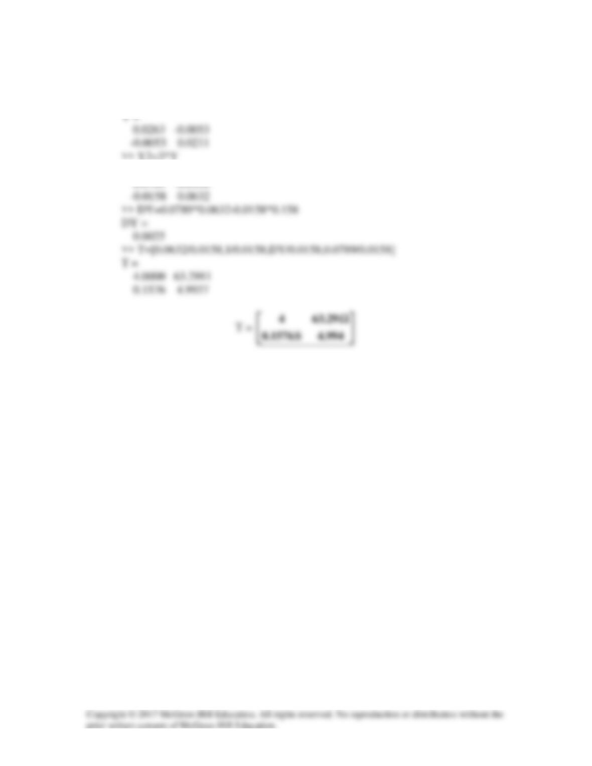
Using MATLAB we get,
T =
F =
Solution 19.74
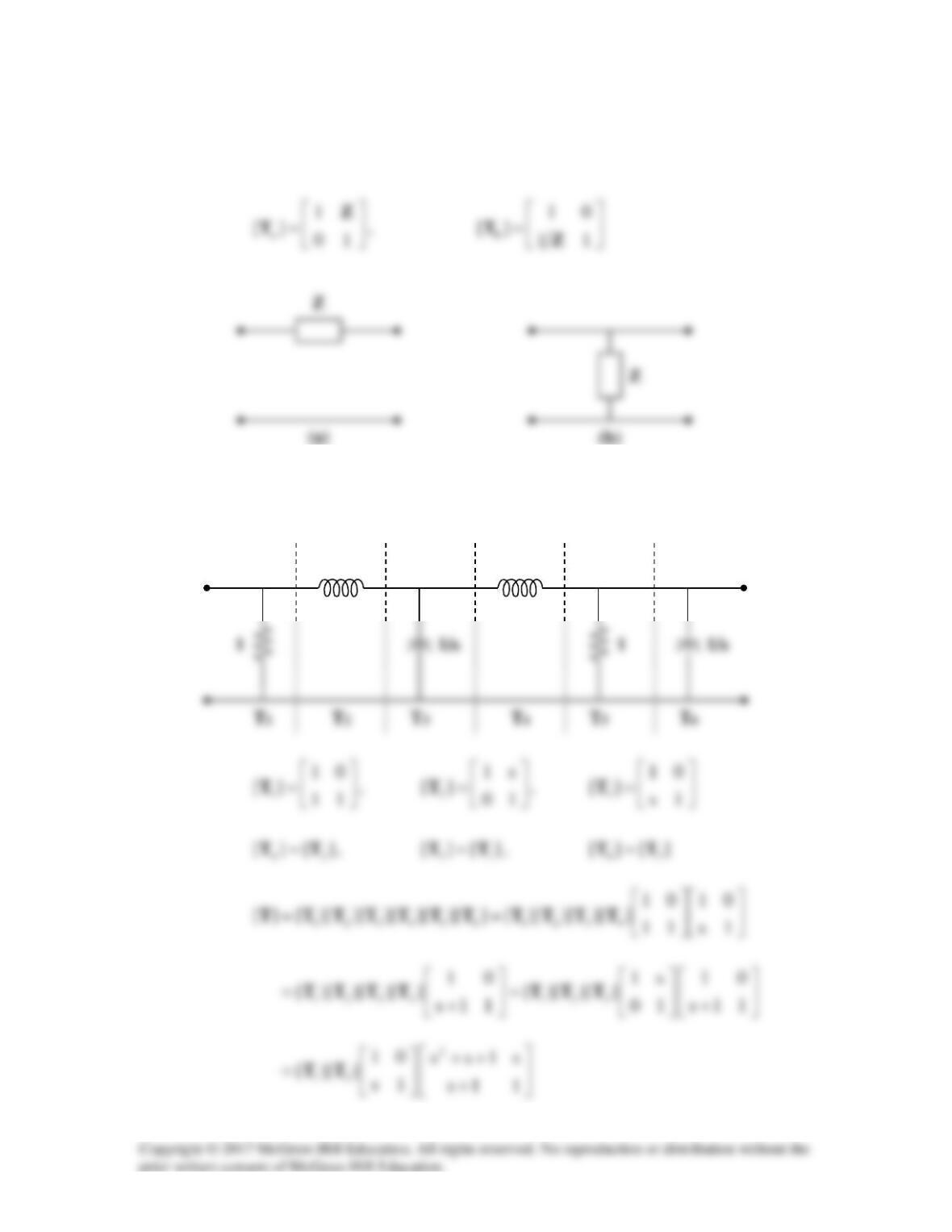
From Prob. 18.35, the transmission parameters for the circuit in Figs. (a) and (b) are
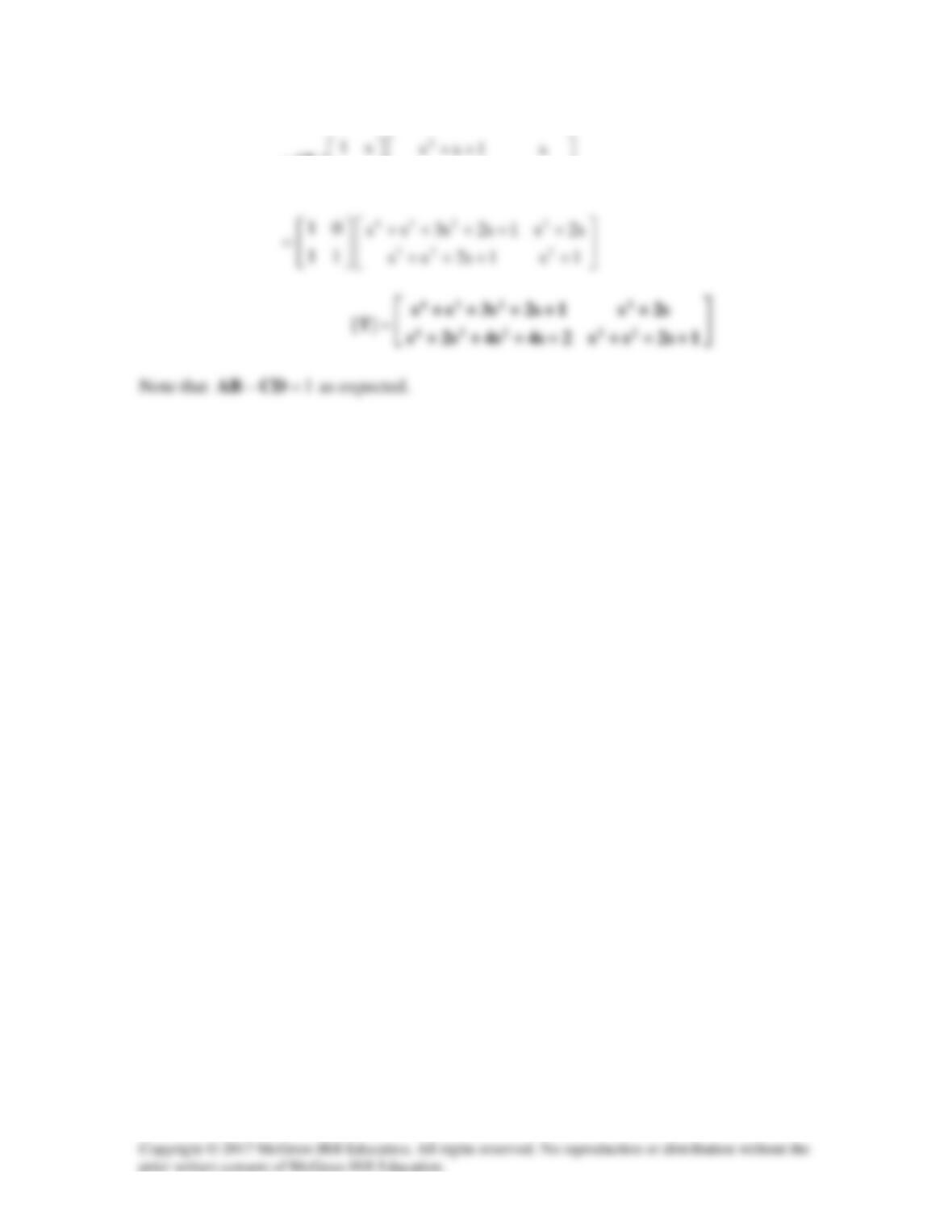
We partition the given circuit into six subcircuits similar to those in Figs. (a) and (b) as
shown in Fig. (c) and obtain
][T
for each.
(a)
s
s
++++
=
1s1s2ss
10
][ 223
1
T
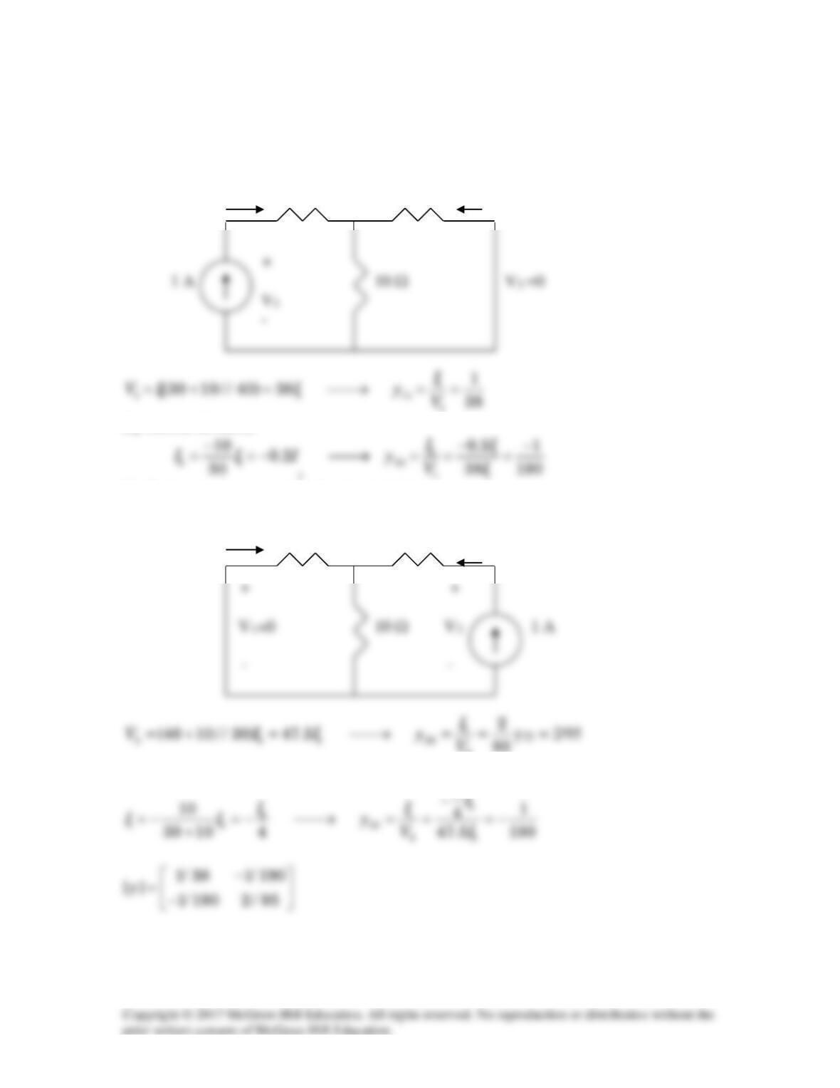
Solution 19.75
(a) We convert [za] and [zb] to T-parameters. For Na,
162440 =−=∆ z
.
∆
42
z/z/z
21z2111
We convert this to y-parameters.
.3BCAD
T−=−=∆
1765.03015.0
B/B/D
−
∆−
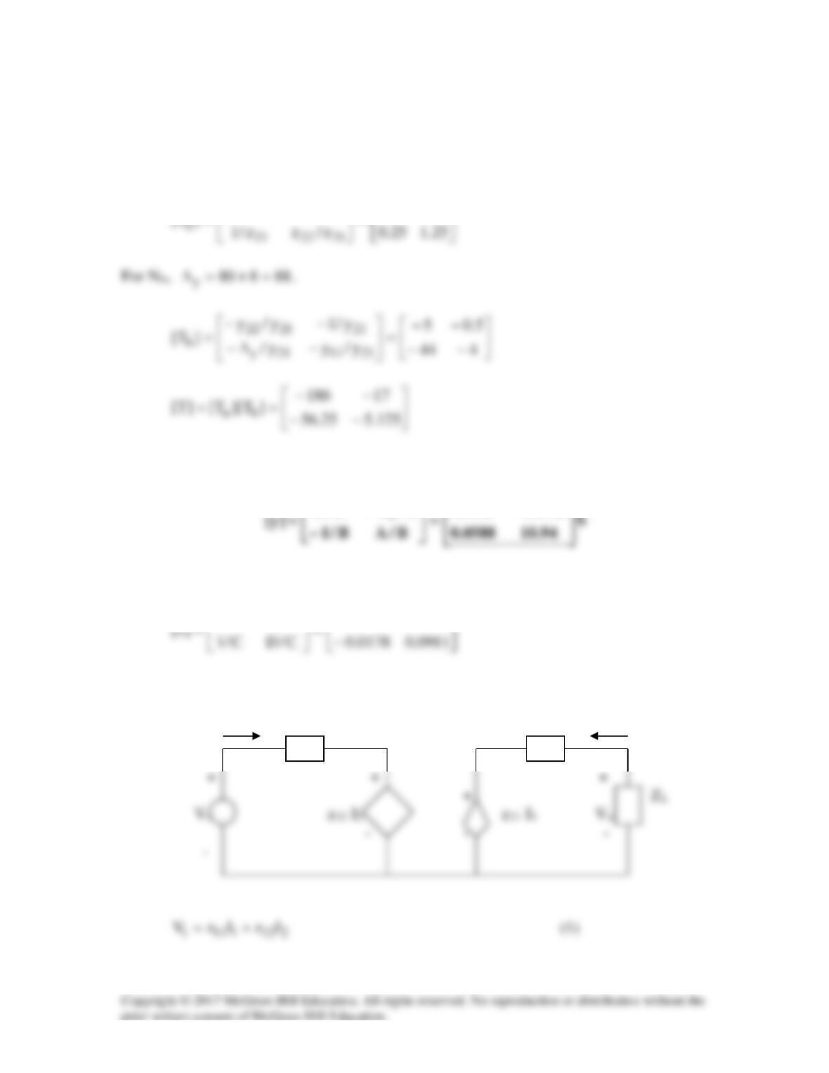
(b) The equivalent z-parameters are
∆
0533.03067.3
C/C/A
Consider the equivalent circuit below.
I1 z11 z22 I2