Solution 6.40
5, 0 2
t t ms
<<
Solution 6.41
( )
∫∫ +−
=+=
−
t
o
t2
t
0
Cdte120
2
1
Cvdt
L
1
i
Solution 6.42
∫ ∫ −=+= t
o
t
o1dt)t(v
5
1
)0(ivdt
L
1
i
Thus,
<<−
10,12
tAt

Solution 6.43
The current in a 150-mH inductor increases from 0 to 60 mA (steady-state). How much
energy is stored in the inductor?
Solution
Solution 6.44
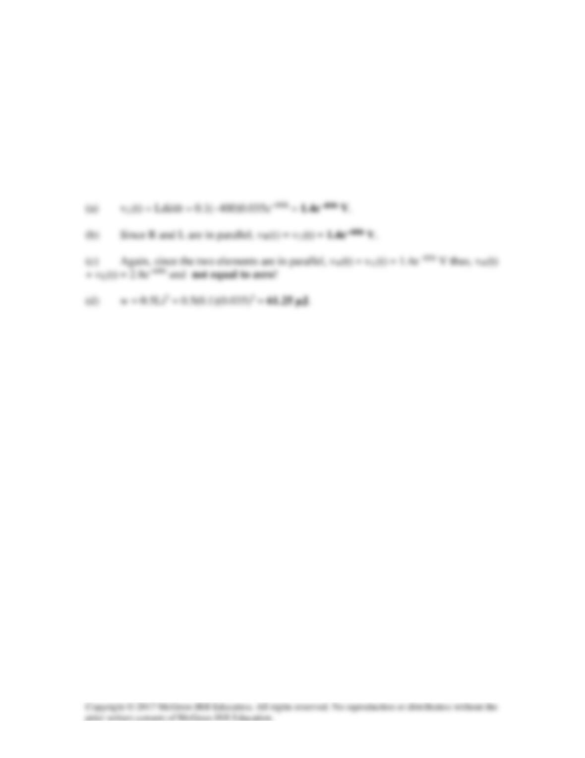
A 100-mH inductor is connected in parallel with a 2-kΩ resistor. The current through the
inductor is i(t) = 35e–400t mA.
(a) Find the voltage vL(t) across the inductor. (b) Find the voltage vR(t) across the
resistor. (c) Is vR(t) + vL(t) = 0? (d) Calculate the energy stored in the inductor at t=0.
Solution
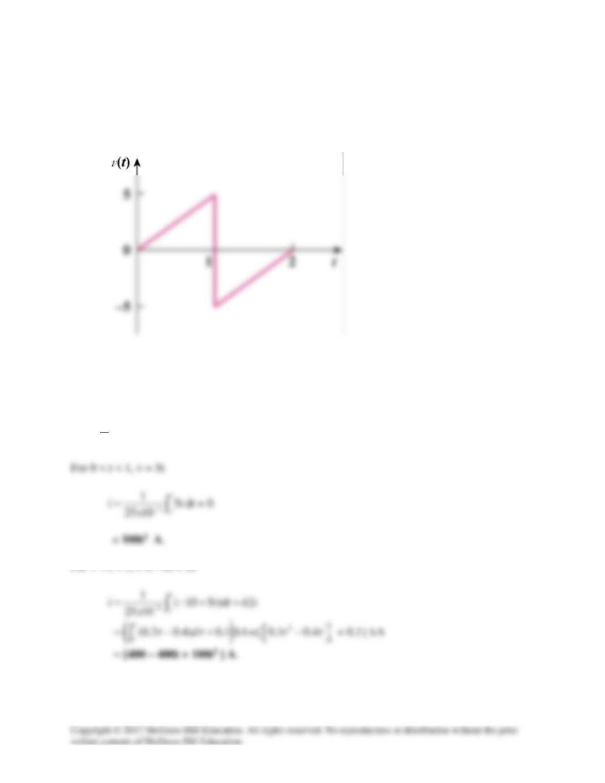
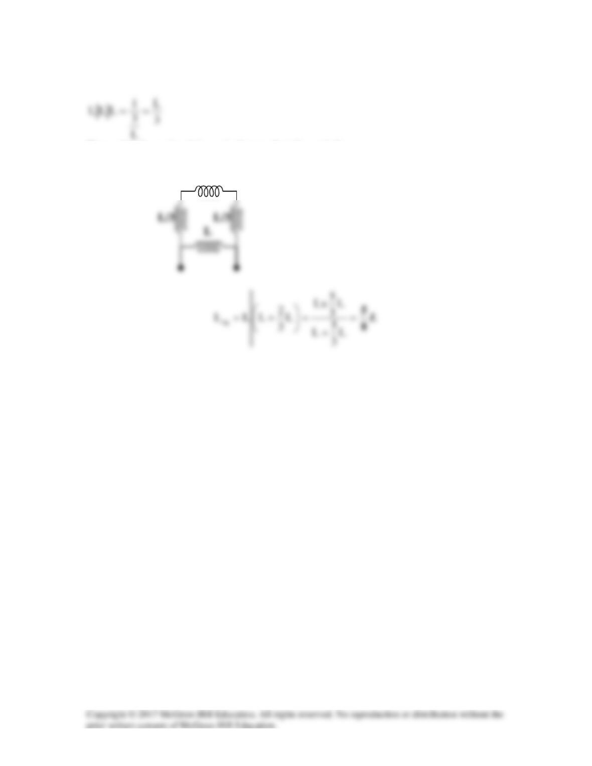
Solution 6.45
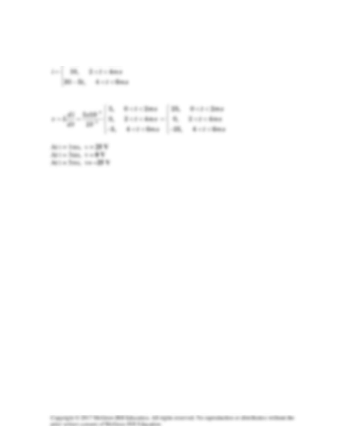
If the voltage waveform in Fig. 6.68 is applied to a 25-mH inductor, find the inductor current i(t)
for 0 < t < 2 seconds. Assume i(0) = 0.
Figure 6.68
For Prob. 6.45.
Solution
i(t) =
1( ) (0)
t
ovt i
L+
∫
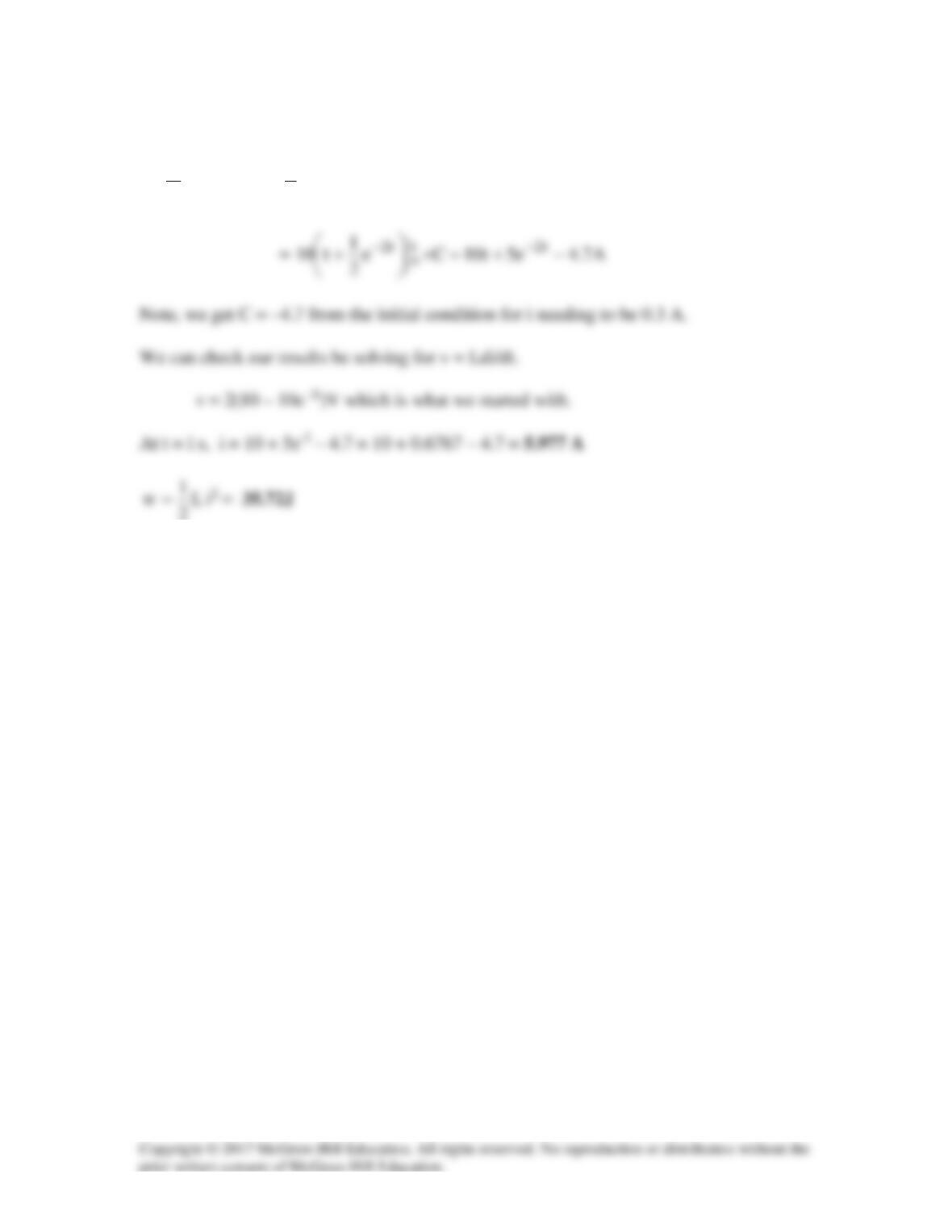
Solution 6.46
Under dc conditions, the circuit is as shown below:
By current division,
=
+
=)3(
24
4
i
L
2A, vc = 0V
Solution 6.47
Under dc conditions, the circuit is equivalent to that shown below:
,
2R
10
)5(
2R
2
iL+
=
+
=
2R
R10
Riv
Lc
+
==
R
Solution 6.48
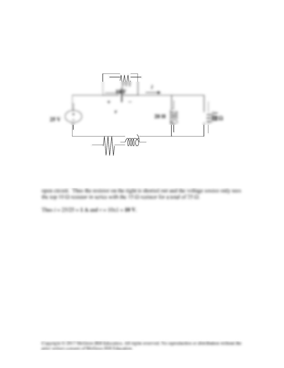
Under steady-state dc conditions, find i and v in the circuit in Fig. 6.71.
Figure 6.71
For Prob. 6.48.
Solution
Under steady–state, the inductor acts like a short–circuit, while the capacitor acts like an
10 H
15
Ω
10
Ω
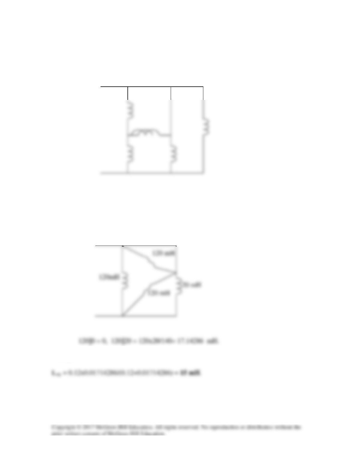
Solution 6.49
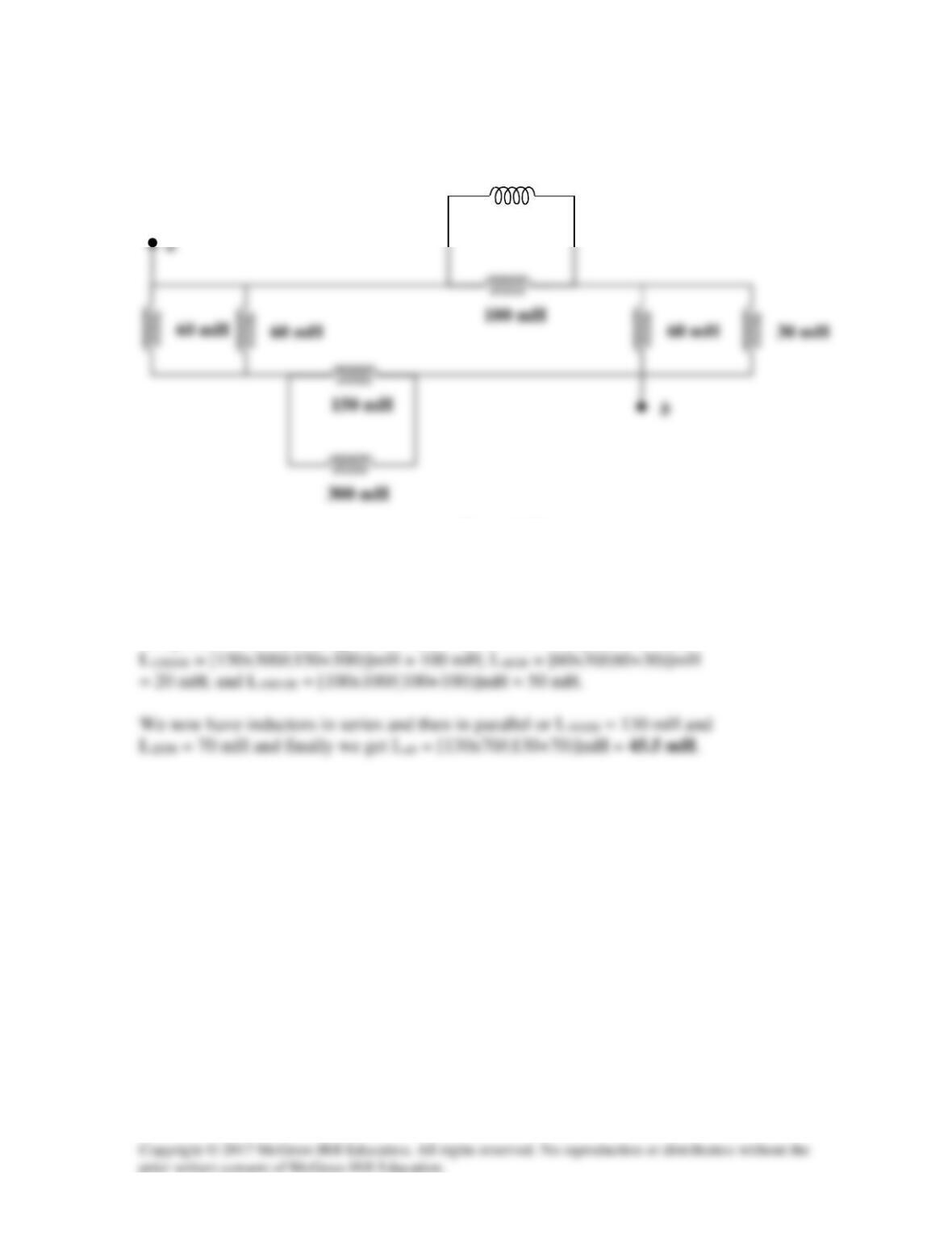
Find the equivalent inductance of the circuit in Fig. 6.72. Assume all inductors are
40 mH.
Figure 6.72
For Prob. 6.49.
Solution
Converting the wye-subnetwork to its equivalent delta gives the circuit below.
Finally,

Solution 6.50
16mH in series with 14 mH = 16+14=30 mH
Solution 6.51
Solution 6.52
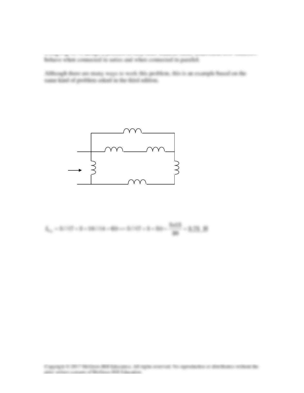
Problem
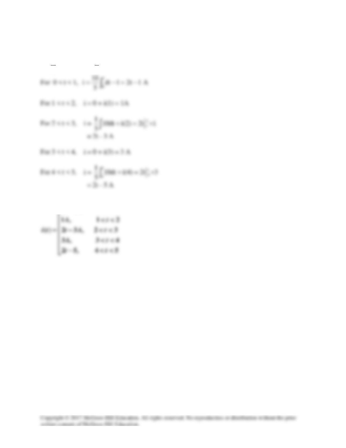
Find Leq in the circuit of Fig. 6.74.
10 H
4 H 6 H
5 H 3 H
Leq
7 H
Figure 6.74 For Prob. 6.52.
Solution
Solution 6.53
[ ]
)48(6)128(58106L
eq
+++++=
Solution 6.54
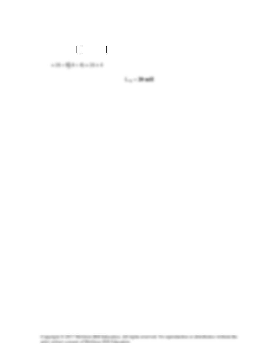
Find the equivalent inductance looking into the terminals of the circuit in Fig. 6.76.
Figure 6.76
For Prob. 6.54.
Solution
The parallel combinations gives us L6060 = [60×60/(60+60)]mH = 30 mH;
100 mH
Solution 6.55
(a) L//L = 0.5L, L + L = 2L
Solution 6.56
Hence the given circuit is equivalent to that shown below:
L
L
Solution 6.57
Let
dt
di
Lv eq
=
(1)
and
Incorporating (3) and (4) into (5),
Substituting this into (2) gives
Comparing this with (1),
Solution 6.58
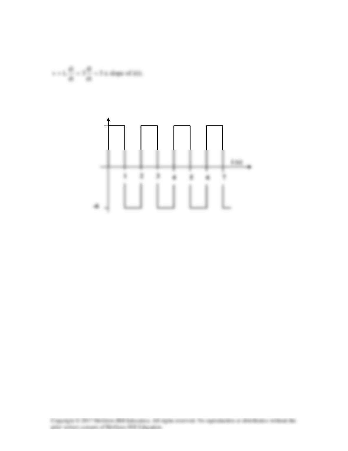
Thus v is sketched below:
2
3
4
1
5
7
6
v(t) (V)
6
Solution 6.59
(a)
( )
dt
di
LLv
21s
+=
(b)
dt
di
L
dt
di
Lvv 2
2
1
12i ===