
Solution 6.21
4µF in series with 12µF = (4×12)/16 = 3µF
3µF in parallel with 3µF = 6µF
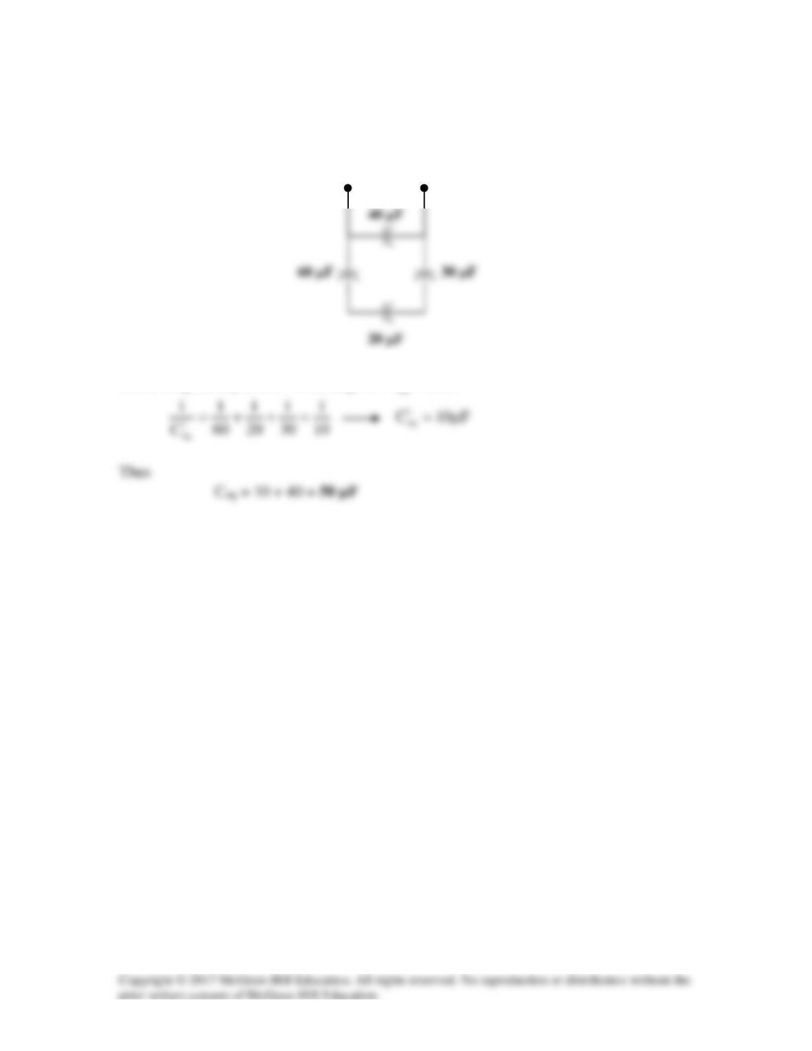
Solution 6.22
Combining the capacitors in parallel, we obtain the equivalent circuit shown below:
Combining the capacitors in series gives
1
eq
C
, where
a
b
Solution 6.23
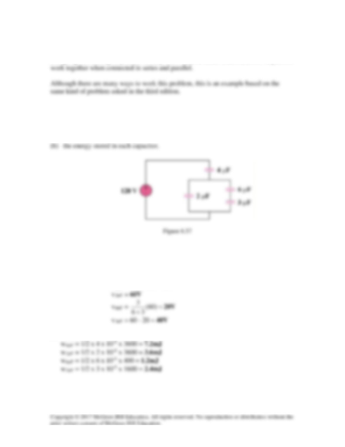
Using Fig. 6.57, design a problem to help other students better understand how capacitors
Problem
For the circuit in Fig. 6.57, determine:
(a) the voltage across each capacitor,
Solution
(a) 3µF is in series with 6µF 3×6/(9) = 2µF
v4µF = 1/2 x 120 = 60V
(b) Hence w = 1/2 Cv2
Solution 6.24
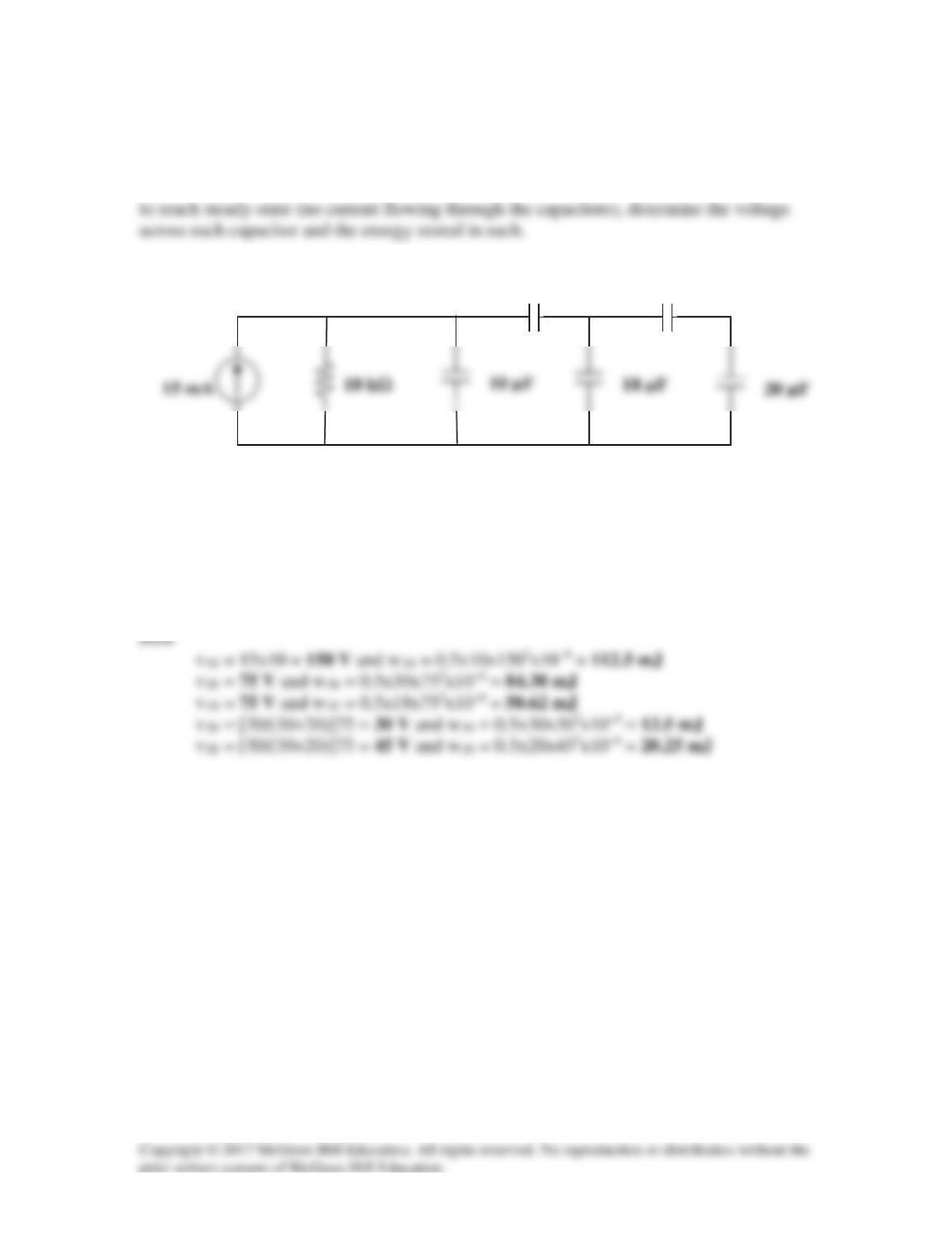
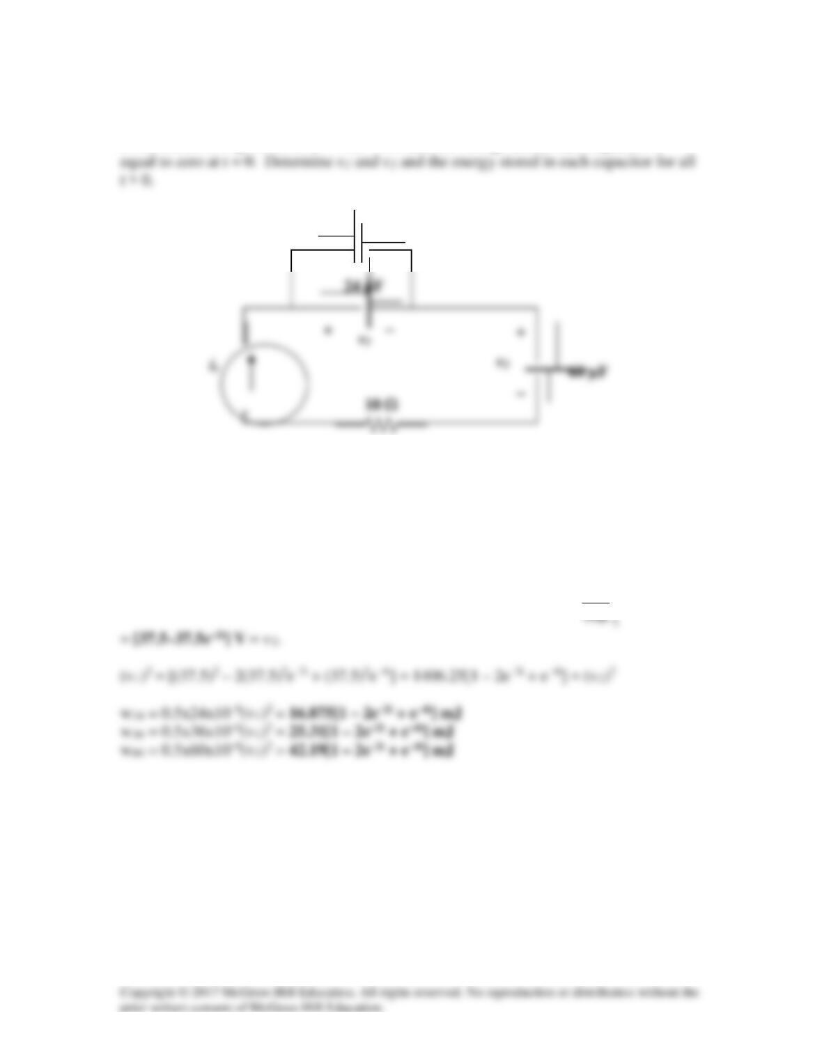
In the circuit shown in Fig. 6.58 assume that the capacitors were initially uncharged and
that the current source has been connected to the circuit long enough for all the capacitors
20 µF
15 mA
18 µF
Figure 6.58
For Prob. 6.24.
Solution
Reducing the capacitance starting from right to left. 30µF in series with 20µF we get,
30×20µF/(30+20) = 12µF in parallel with 18µF we get (12+18)µF = 30µF.
30 µF
30 µF
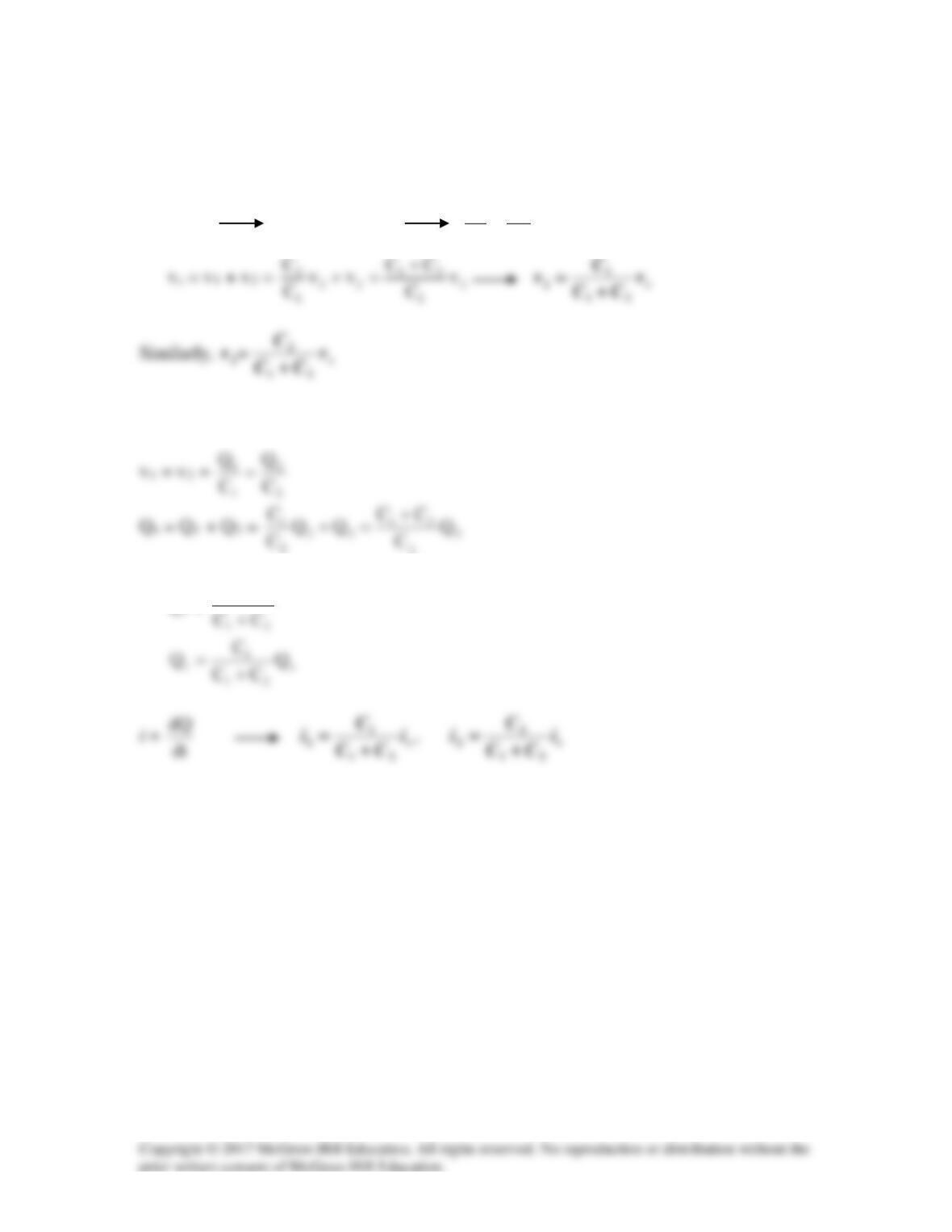
Solution 6.25
(a) For the capacitors in series,
Q1 = Q2 C1v1 = C2v2
1
2
2
1
C
C
v
v=
(b) For capacitors in parallel
2
or
Q2 =
2
C
Solution 6.26
Three capacitors, C1 = 5
µ
F, C2 = 10
µ
F, and C3 = 20
µ
F, are connected in parallel
across a 200–V source. Determine:
Solution
(a) Ceq = C1 + C2 + C3 = 35µF

Solution 6.27
Solution
If they are all connected in parallel, we get Ctotal = 4×10 µF = 40 µF.
Solution 6.28
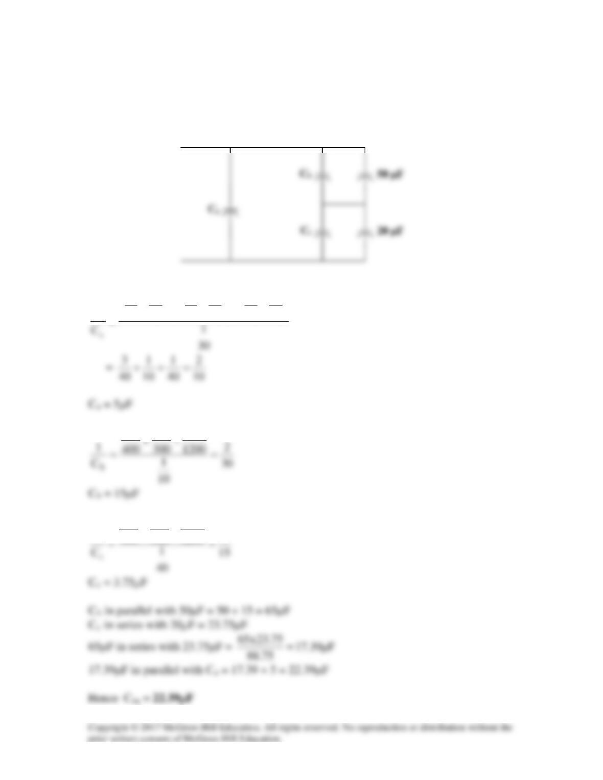
We may treat this like a resistive circuit and apply delta–wye transformation, except that
R is replaced by 1/C.
40
1
30
1
30
1
10
1
40
1
10
1
1
+
+
1
1
1
4
1200
1
300
1
400
1
1
++
Solution 6.29
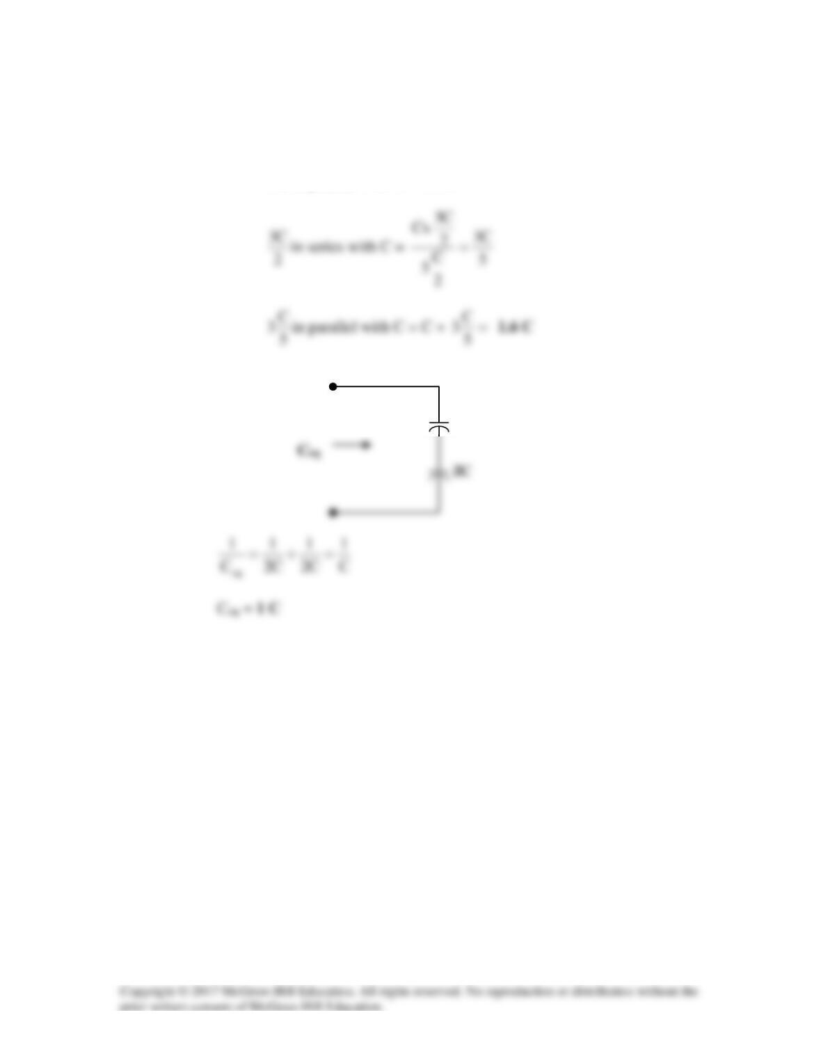
(a) C in series with C = C/(2)
C/2 in parallel with C = 3C/2
(b)
2C
2C
Solution 6.30
vo =
∫+
t
o)0(iidt
C
1
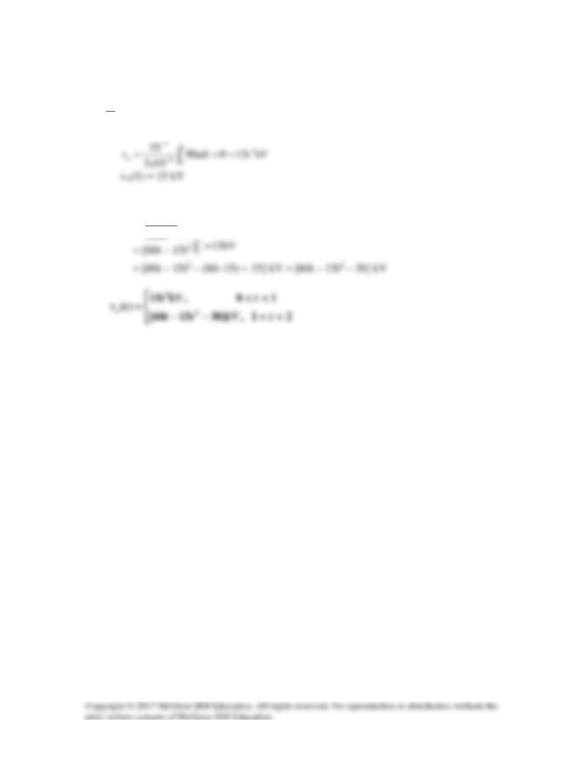
For 0 < t < 1, i = 90t mA,
For 1< t < 2, i = (180 – 90t) mA,
vo =
∫+−
−
−t
o
vdtt
6
3
)1()90180(
10
Solution 6.31
<<
10,30
ttmA
Ceq = 4 + 6 = 10µF
For 0 < t < 1,
For 1 < t < 3,
For 3 < t < 5,
<<
stkVt
10,5.1
2
dt
dv
10x6
dt
dv
Ci
6
11
−
==

<<
sttmA
10,12
Solution 6.32
In the circuit in Fig. 6.64, let is = 4.5e–2t mA and the voltage across each capacitor is
Figure 6.64
For Prob. 6.32.
Solution
Combining the 36 µF with the 24 µF we get 60 µF which leads to v1 =
t
2τ
14.5e mdτ
−
∫
36 µF

Solution 6.33
Because this is a totally capacitive circuit, we can combine all the capacitors using the
property that capacitors in parallel can be combined by just adding their values and we
combine capacitors in series by adding their reciprocals. However, for this circuit we
only have the three capacitors in parallel.

Solution 6.34
Solution
i = 10e–t/2
2/3
2
1
)10(1025 t
ex
dt
di
Lv −−
−
==

Solution 6.35
Solution
v = L(di/dt) or L = v/(di/dt)
Solution 6.36
Design a problem to help other students to better understand how inductors work.
Problem
The current through a 12-mH inductor is
2
( ) 30 A, t 0.
t
i t te −
= ≥
Determine: (a) the
voltage across the inductor, (b) the power being delivered to the inductor at t = 1 s,
(c) the energy stored in the inductor at t = 1 s.
Solution

Solution 6.37
t100cos)100(4x10x12
dt
di
Lv
3−
==

Chapter 6.38
Solution 6.39
The voltage across a 50-mH inductor is given by
Solution
)0(
1
0iid
L
i
dt
di
Lv t+=→=
∫
τ