Solution 5.56
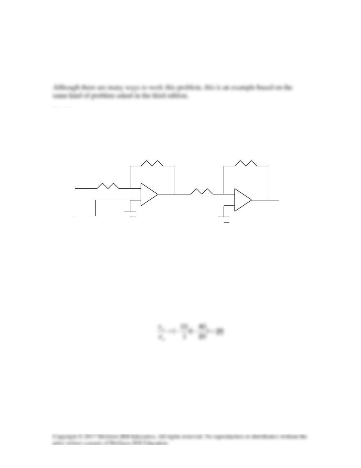
Using Fig. 5.83, design a problem to help other students better understand cascaded op
amps.
Problem
Calculate the gain of the op amp circuit shown in Fig. 5.83.
10 kΩ 40 kΩ
1 kΩ
20 kΩ
+
vi
–
Figure 5.83 For Prob. 5.56.
Solution
Each stage is an inverting amplifier. Hence,
–
+
–
+
Solution 5.57
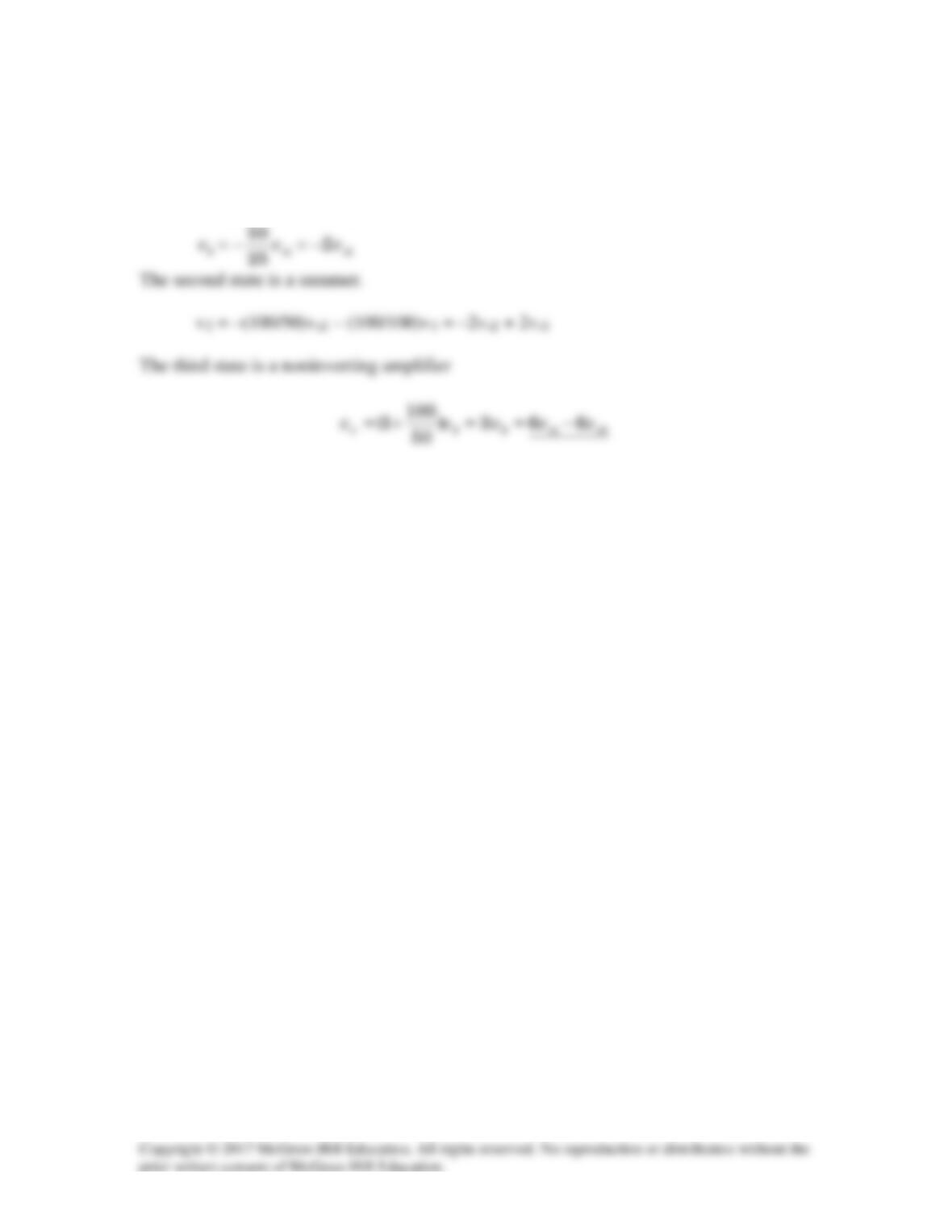
Let v1 be the output of the first op amp and v2 be the output of the second op amp.
The first stage is an inverting amplifier.
Solution 5.58
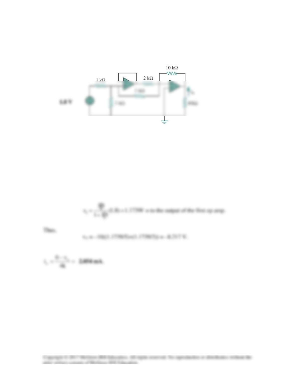
Calculate io in the op amp circuit of Fig. 5.85.
Figure 5.85
For Prob. 5.58.
Solution
Looking at the circuit, the voltage at the right side of the 5-kΩ resistor must be at 0V if
the op amps are working correctly. Thus the 1-kΩ is in series with the parallel
combination of the 3-kΩ and the 5–kΩ. By voltage division, the input to the voltage
follower is:
Solution 5.59
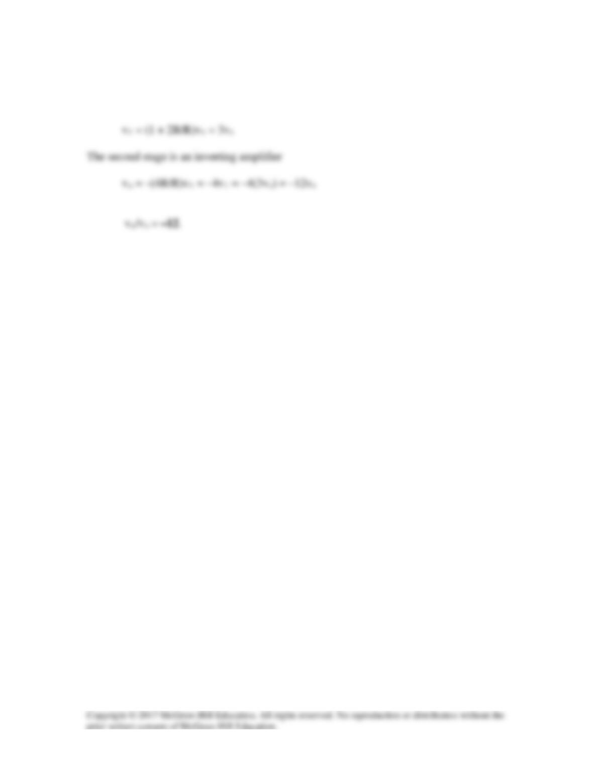
The first stage is a noninverting amplifier. If v1 is the output of the first op amp,
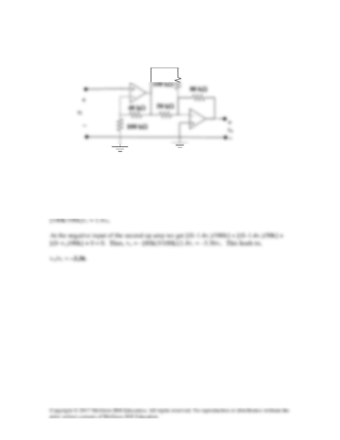
Solution 5.60
Calculate vo/vi in the op amp circuit in Fig. 5.87.
Figure 5.87
For Prob. 5.60.
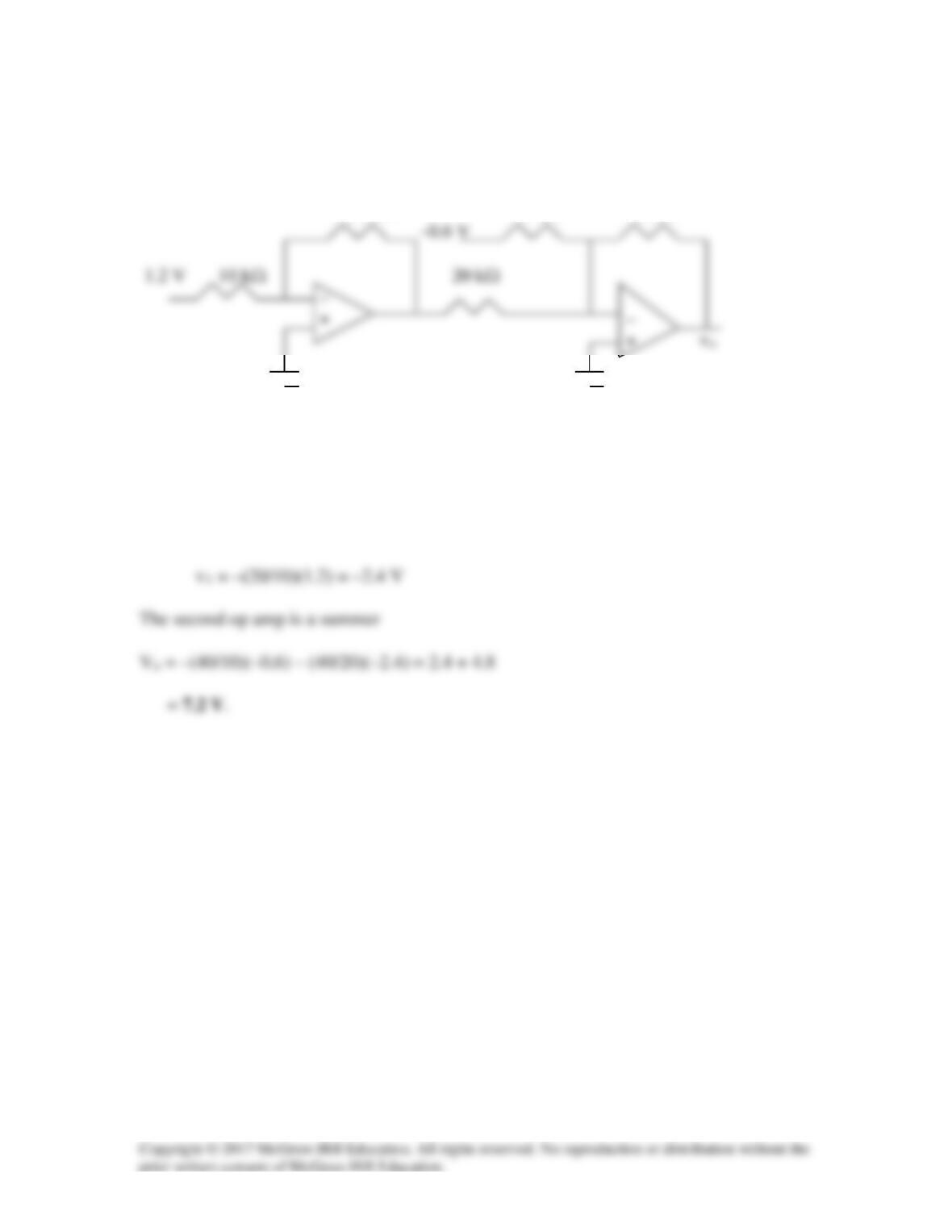
Solution
The first stage is a noninverting amp with an output voltage equal to
Solution 5.61
Determine vo in the circuit of Fig. 5.88.
20 kΩ 10 kΩ 40 kΩ
Figure 5.88
For Prob. 5.61.
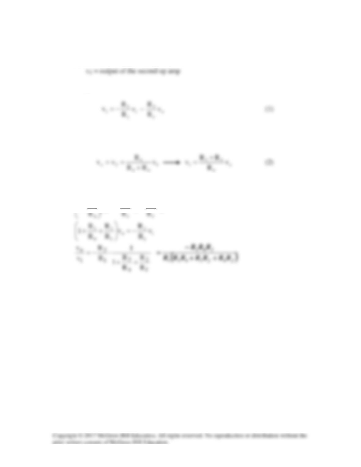
Solution
The first op amp is an inverter. If v1 is the output of the first op amp,
Solution 5.62
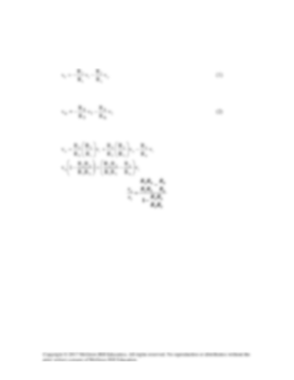
Let v1 = output of the first op amp
The first stage is a summer
The second stage is a follower. By voltage division
From (1) and (2),
i
2
o
3v
R
v
R
1−=
+
o
2
v
R
−
Solution 5.63
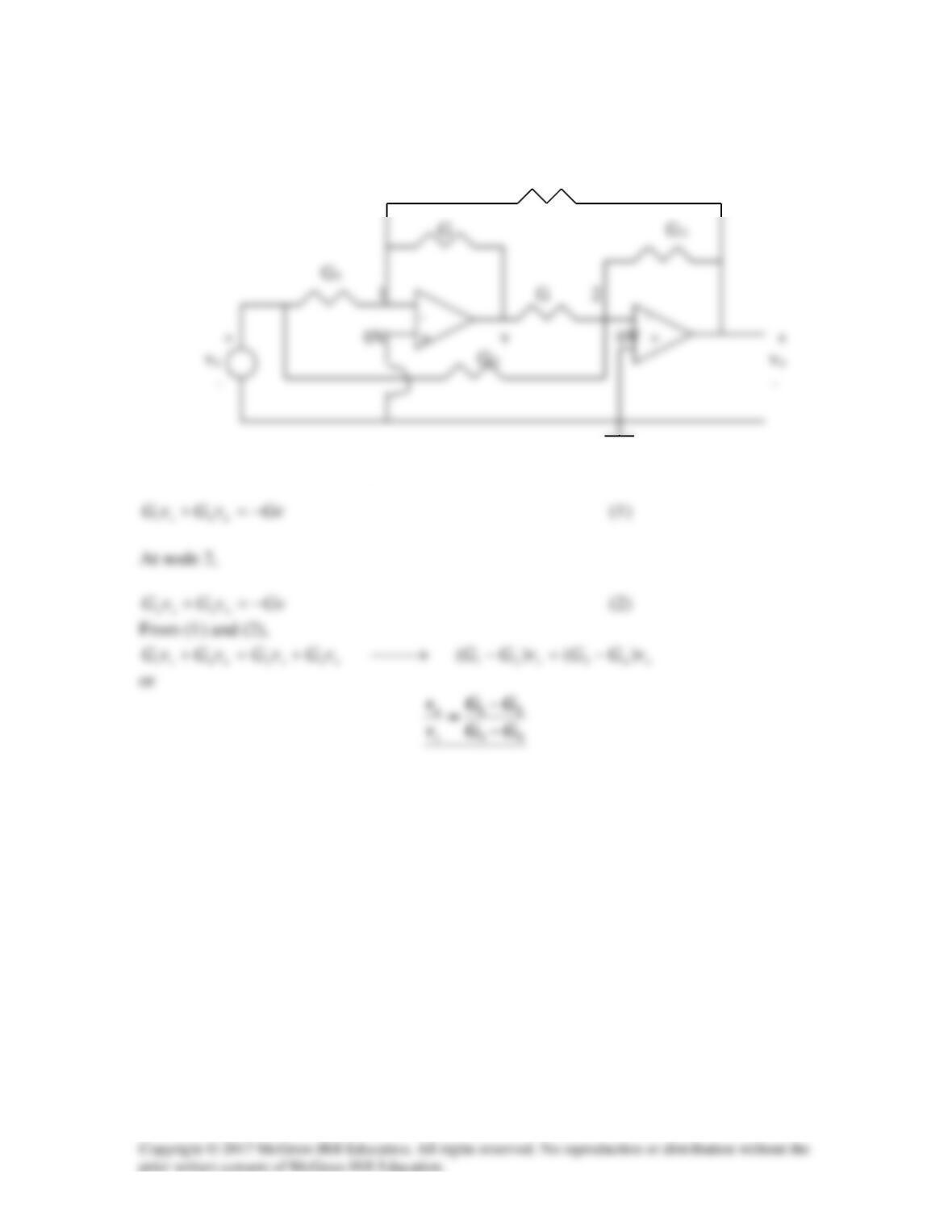
The two op amps are summers. Let v1 be the output of the first op amp. For the first
stage,
For the second stage,
Combining (1) and (2),
Solution 5.64
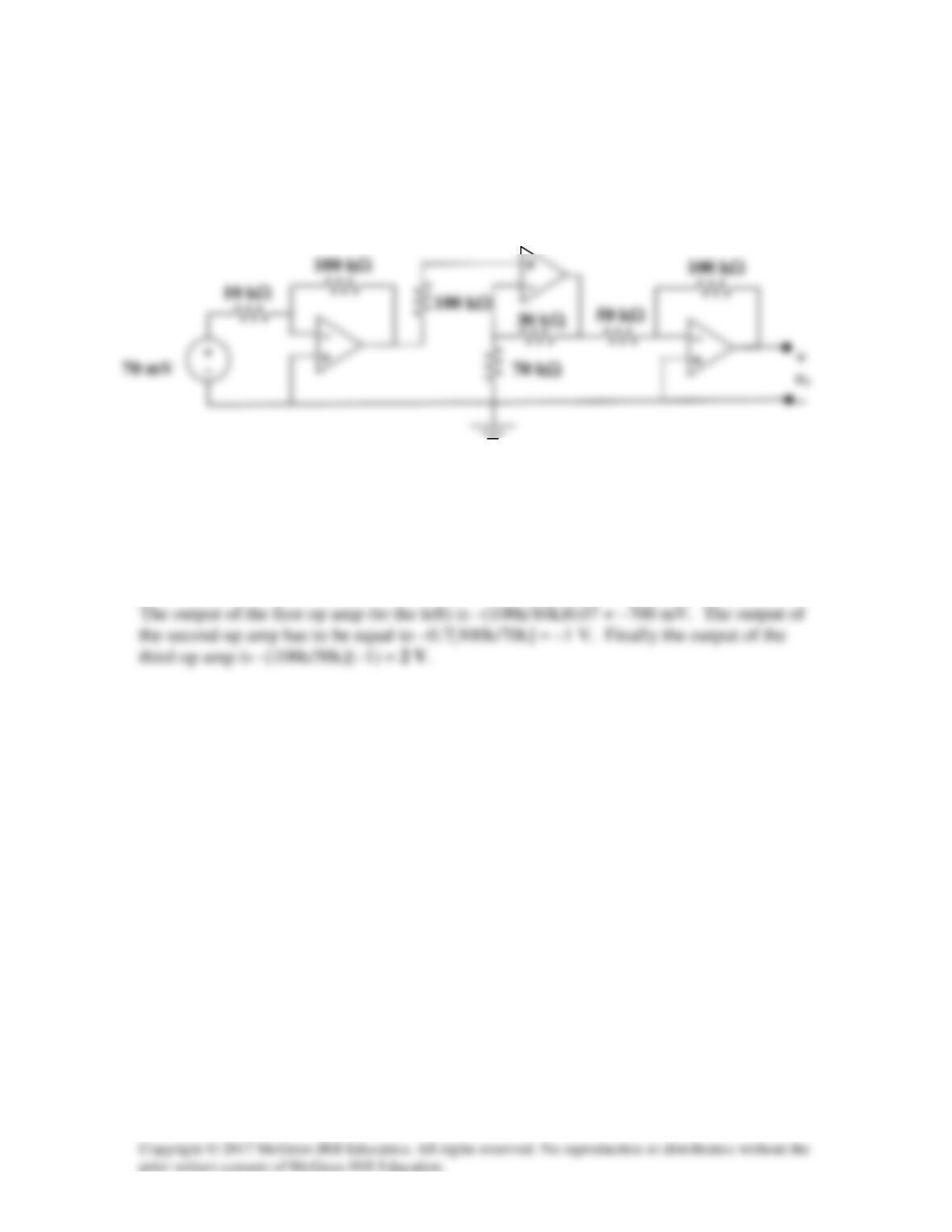
G4
At node 1, v1=0 so that KCL gives
Solution 5.65
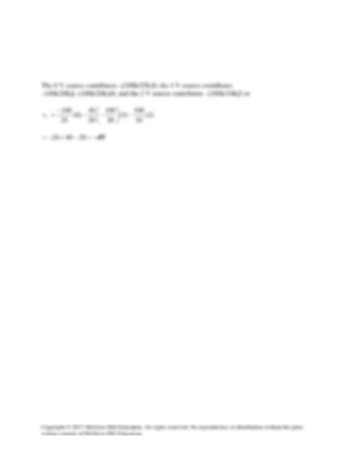
Find vo in the op amp circuit of Fig. 5.92.
Figure 5.92
For Prob. 5.65.
Solution
Solution 5.66
We can start by looking at the contributions to vo from each of the sources and the fact that each
of them go through inverting amplifiers.
Solution 5.67
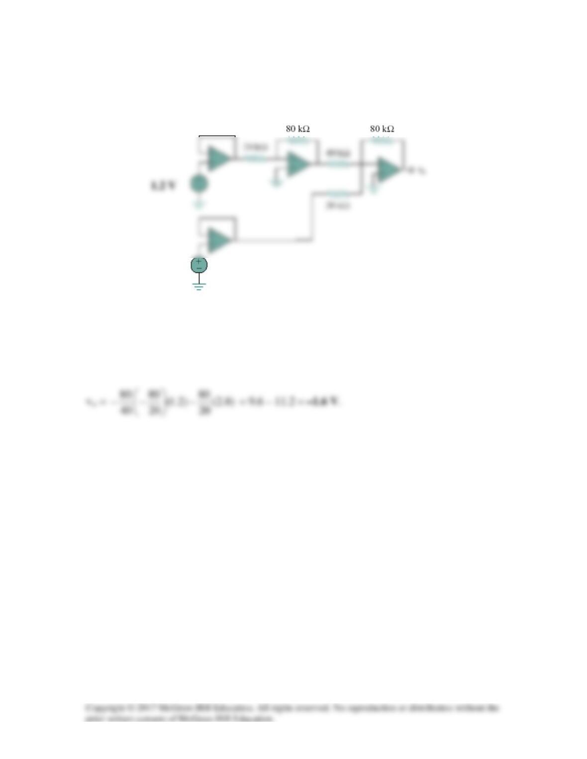
Obtain the output vo in the circuit of Fig. 5.94.
1.2 V
Figure 5.94
For Prob. 5.67.
Solution
2.8 V
Solution 5.68
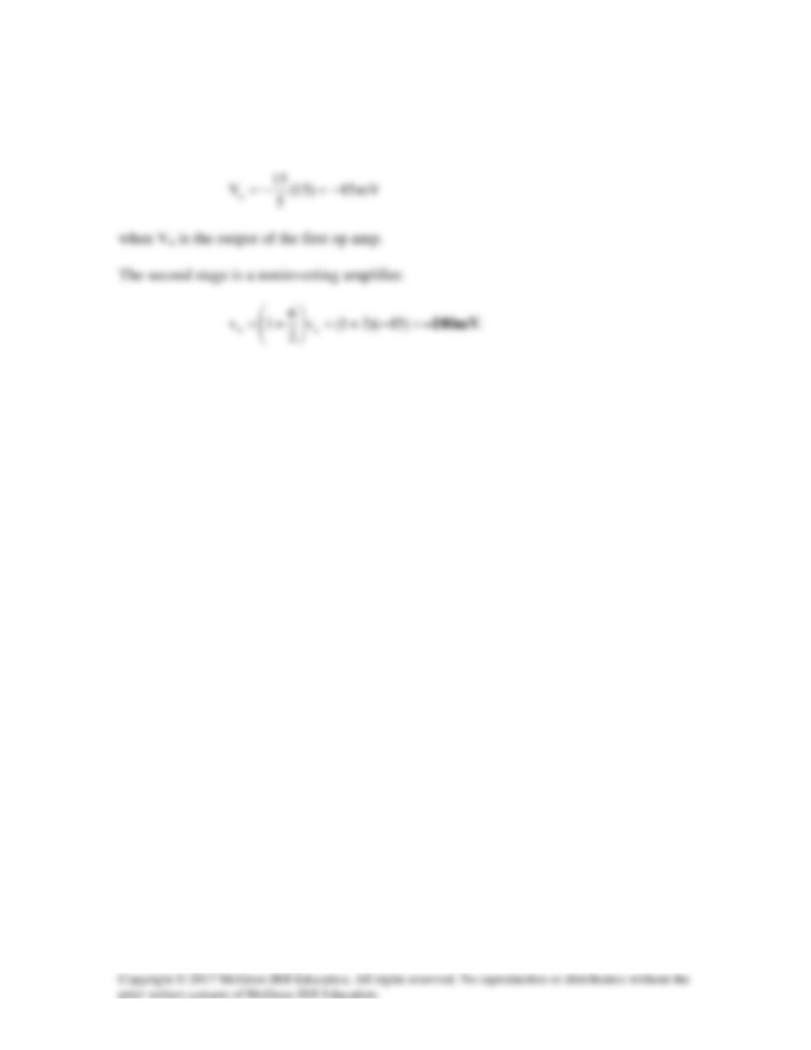
If Rq = ∞, the first stage is an inverter.
Solution 5.69
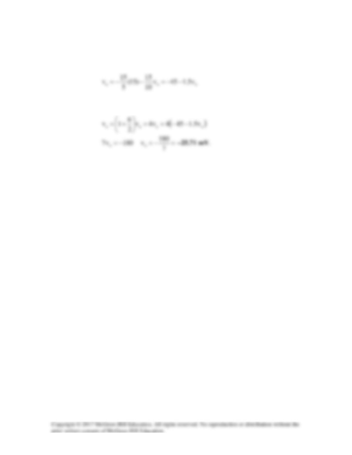
In this case, the first stage is a summer
For the second stage,
Solution 5.70
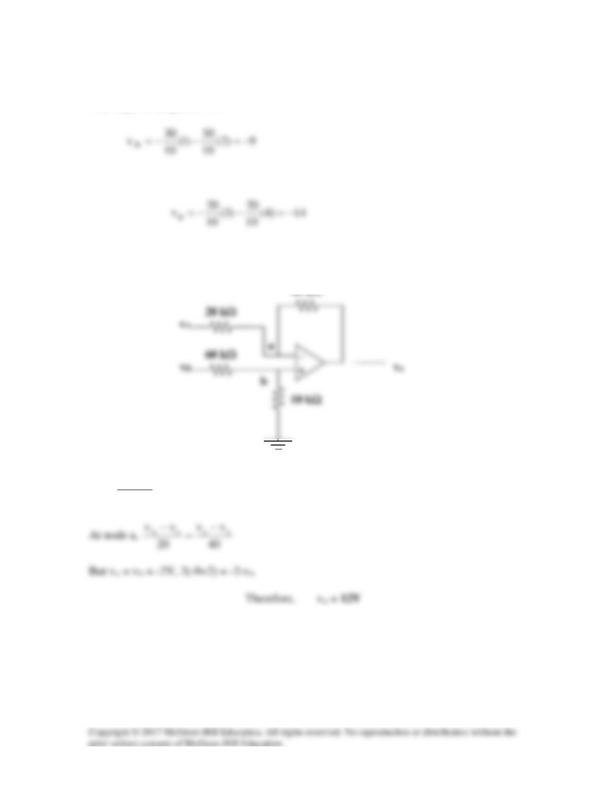
The output of amplifier A is
The output of amplifier B is
V2)14(
1060
10
vb−=−
+
=
Solution 5.71
20k
Ω
Ω
Ω
Ω
1.5 V 80k
Ω
–
– 10k
Ω
+ +
vo
Ω
Ω
+
2.25V 50k
Ω
Ω
Solution 5.72
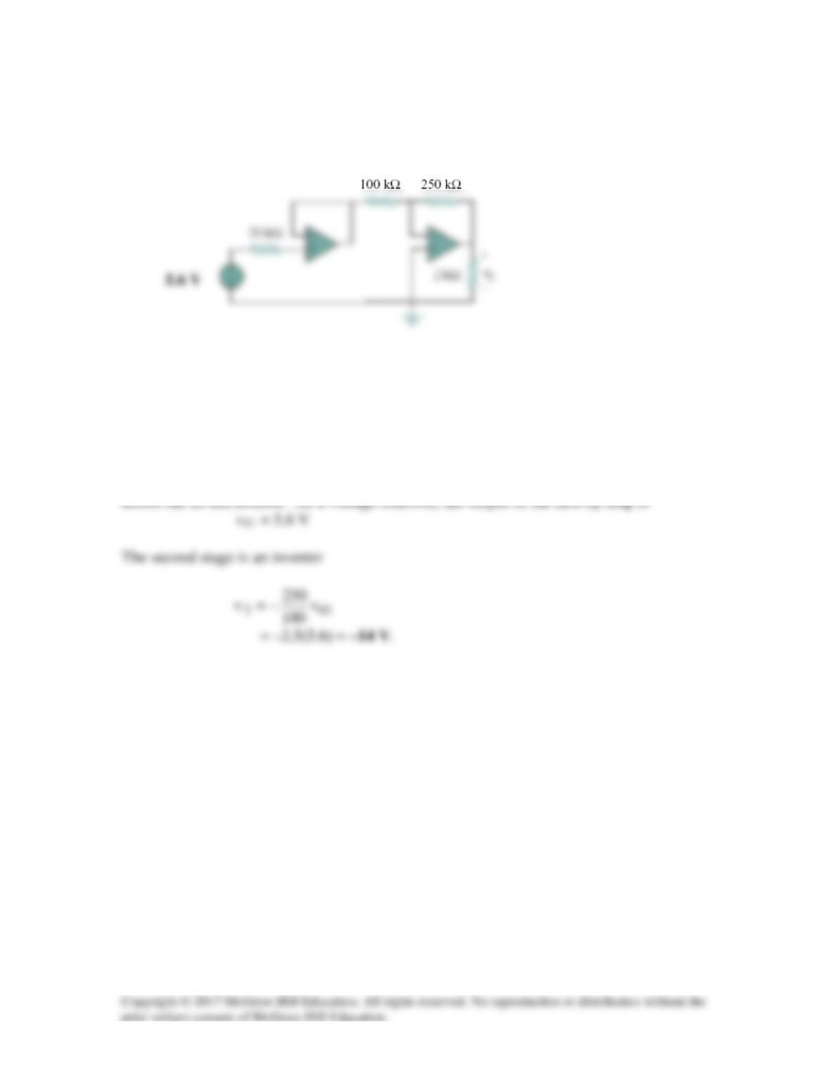
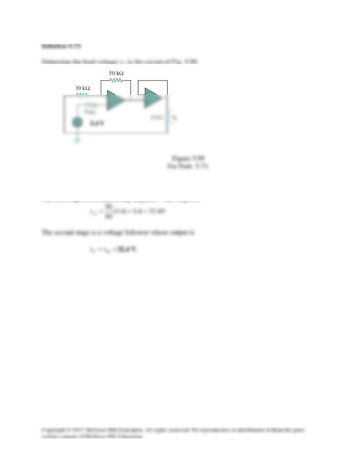
Find the load voltage vL in the circuit of Fig. 5.98.
Figure 5.98
For Prob. 5.72.
Solution
Since no current flows into the input terminals of ideal op amp, there is no voltage drop
Solution
The first stage is a noninverting amplifier. The output is
Solution 5.74
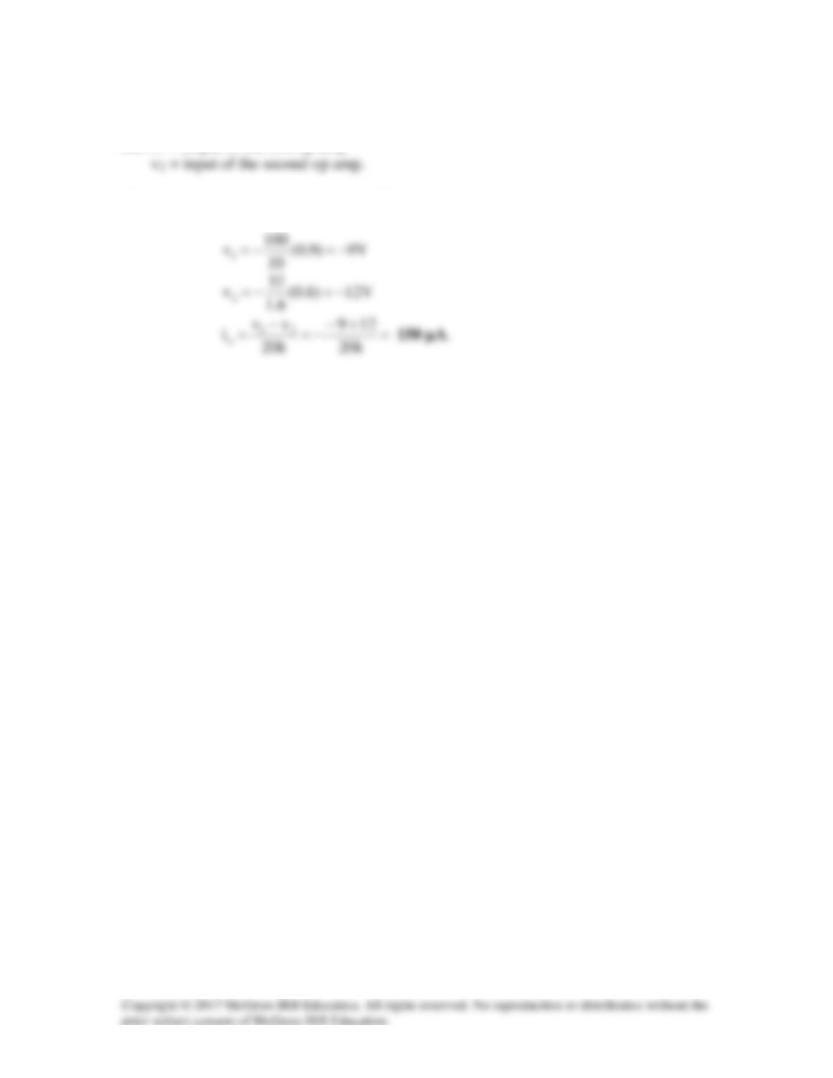
Let v1 = output of the first op amp
The two sub-circuits are inverting amplifiers
Solution 5.75
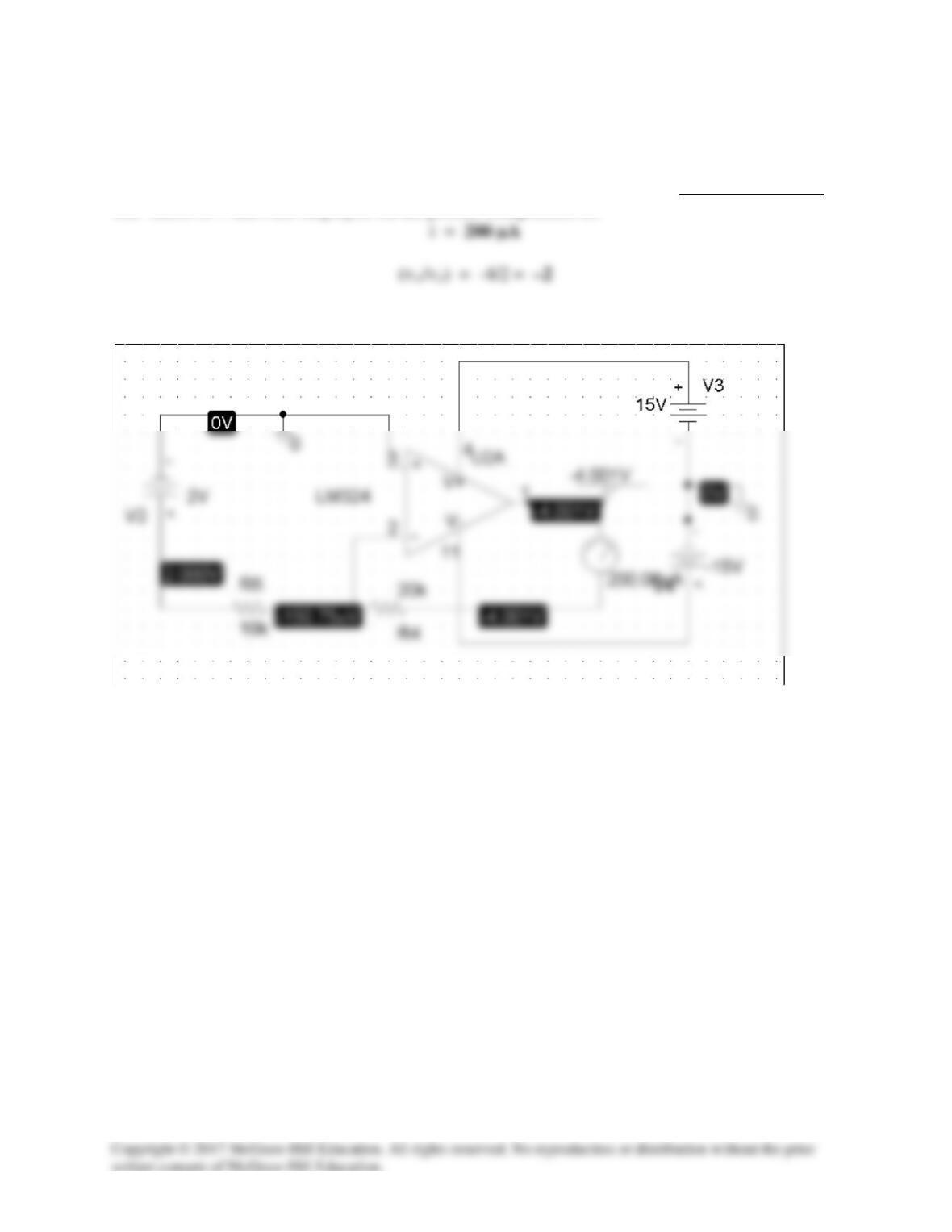
The schematic is shown below. Pseudo-components VIEWPOINT and IPROBE are involved as
shown to measure vo and i respectively. Once the circuit is saved, we click Analysis | Simulate.
The values of v and i are displayed on the pseudo-components as:
The results are slightly different than those obtained in Example 5.11.