
Solution 13.87
Solution 13.88
Solution 13.89
n = V2/V1 = 120/240 = 0.5
Solution 13.90
(a) n = V2/V1 = 240/2400 = 0.1
Solution 13.91
Solution 13.92
(a) V2/V1 = N2/N1 = n, V2 = (N2/N1)V1 = (28/1200)4800 = 112 V
Solution 13.93
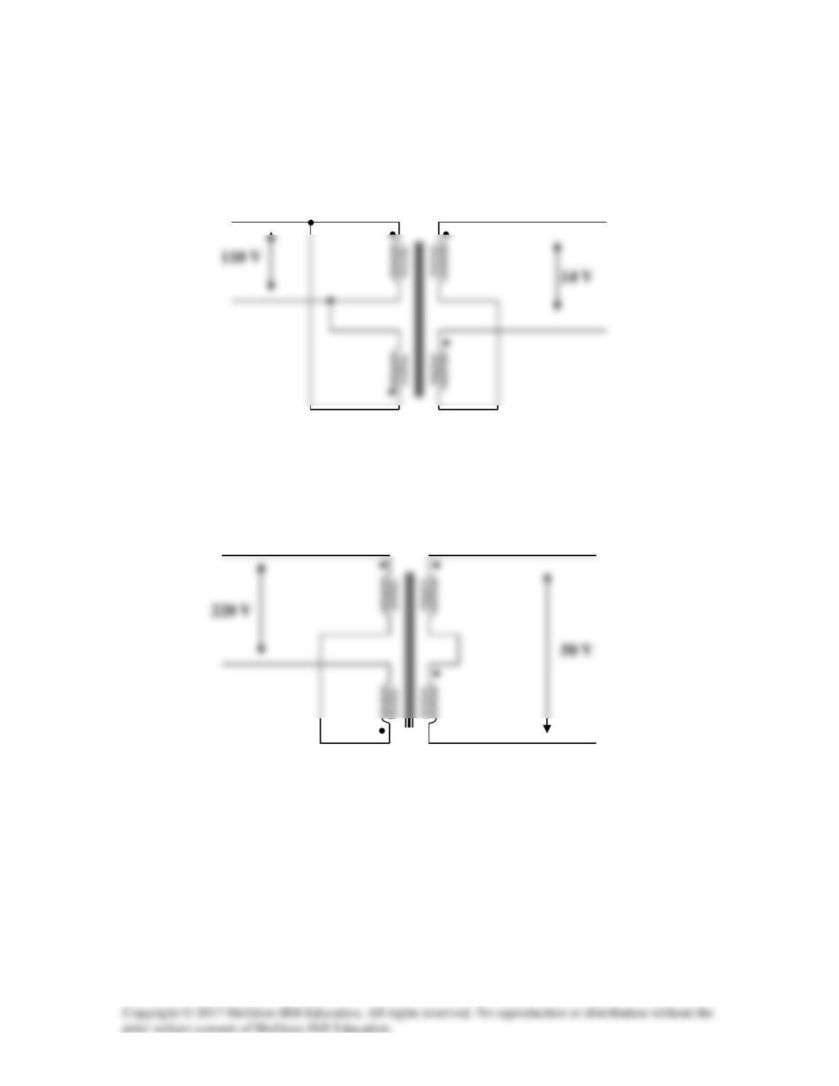
(a) For an input of 110 V, the primary winding must be connected in parallel, with
series aiding on the secondary. The coils must be series opposing to give 14 V. Thus,
the connections are shown below.
(b) To get 220 V on the primary side, the coils are connected in series, with series
aiding on the secondary side. The coils must be connected series aiding to give 50 V.
Thus, the connections are shown below.
Solution 13.94
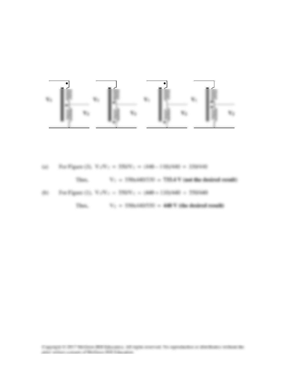
V2/V1 = 110/440 = 1/4 = I1/I2
There are four ways of hooking up the transformer as an auto-transformer. However it is
clear that there are only two outcomes.
(1) and (2) produce the same results and (3) and (4) also produce the same results.
Therefore, we will only consider Figure (1) and (3).
(1)
(2)
(3)
(4)
Solution 13.95
Solution 13.96*
Problem
Some modern power transmission systems now have major, high voltage DC
transmission segments. There are a lot of good reasons for doing this but we will not go
into them here. To go from the AC to DC, power electronics are used. We start with
three-phase AC and then rectify it (using a full-wave rectifier). It was found that using a
delta to wye and delta combination connected secondary would give us a much smaller
ripple after the full–wave rectifier. How is this accomplished? Remember that these are
real devices and are wound on common cores. Hint, using Figures 13.47 and 13.49, and
the fact that each coil of the wye connected secondary and each coil of the delta
connected secondary are wound around the same core of each coil of the delta connected
primary so the voltage of each of the corresponding coils are in phase. When the output
leads of both secondaries are connected through full-wave rectifiers with the same load,
you will see that the ripple is now greatly reduced. Please consult the instructor for more
help if necessary.
Solution
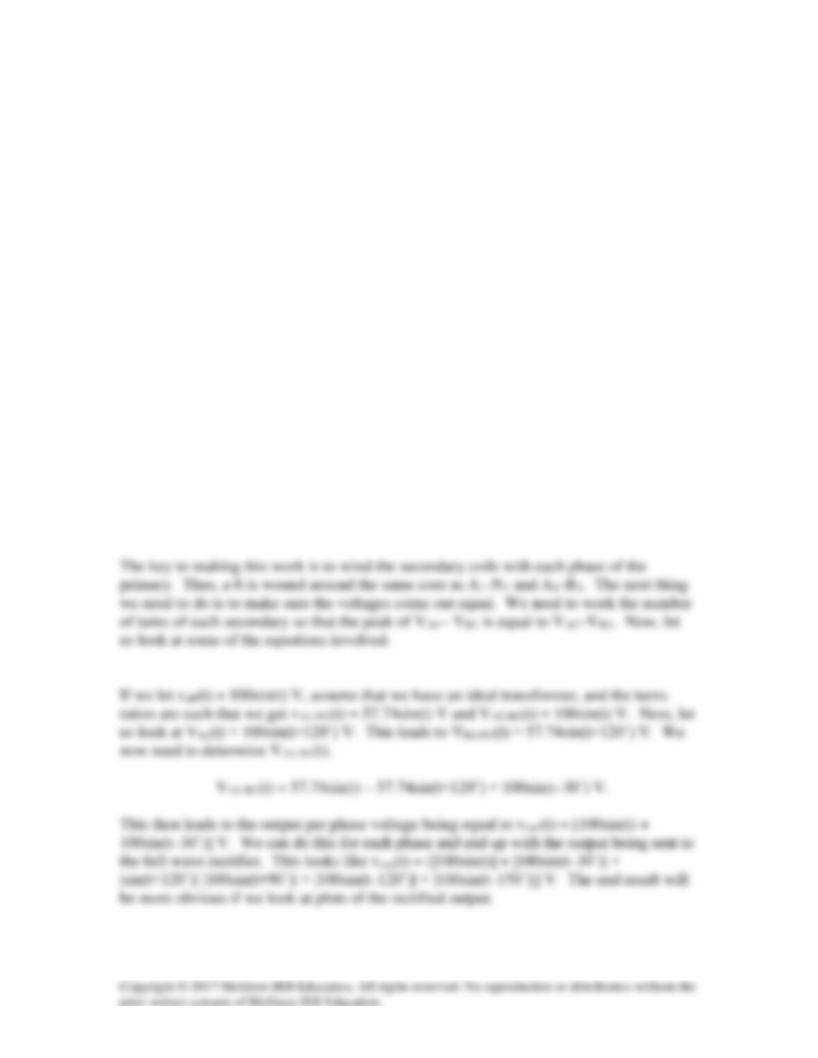
This is a most interesting and very practical problem. The solution is actually quite easy,
you are creating a second set of sine waves to send through the full-wave rectifier, 30˚
out of phase with the first set. We will look at this graphically in a minute. We begin by
showing the transformer components.
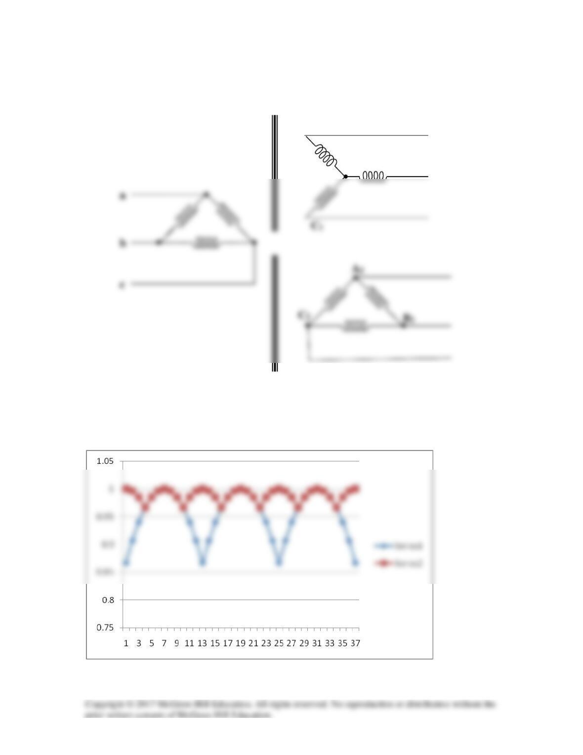
In the plot below we see the normalized (1 corresponds to 100 volts) ripple with only one
of the secondary sets of windings and then the plot with both. Clearly the ripple is
greatly reduced!
B
1
A1
N
1