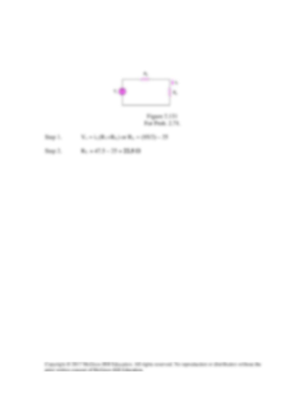
Solution 2.71
Figure 2.131 represents a model of a solar photovoltaic panel. Given that Vs = 95 V,
R1 = 25 Ω, iL = 2 A, find RL.
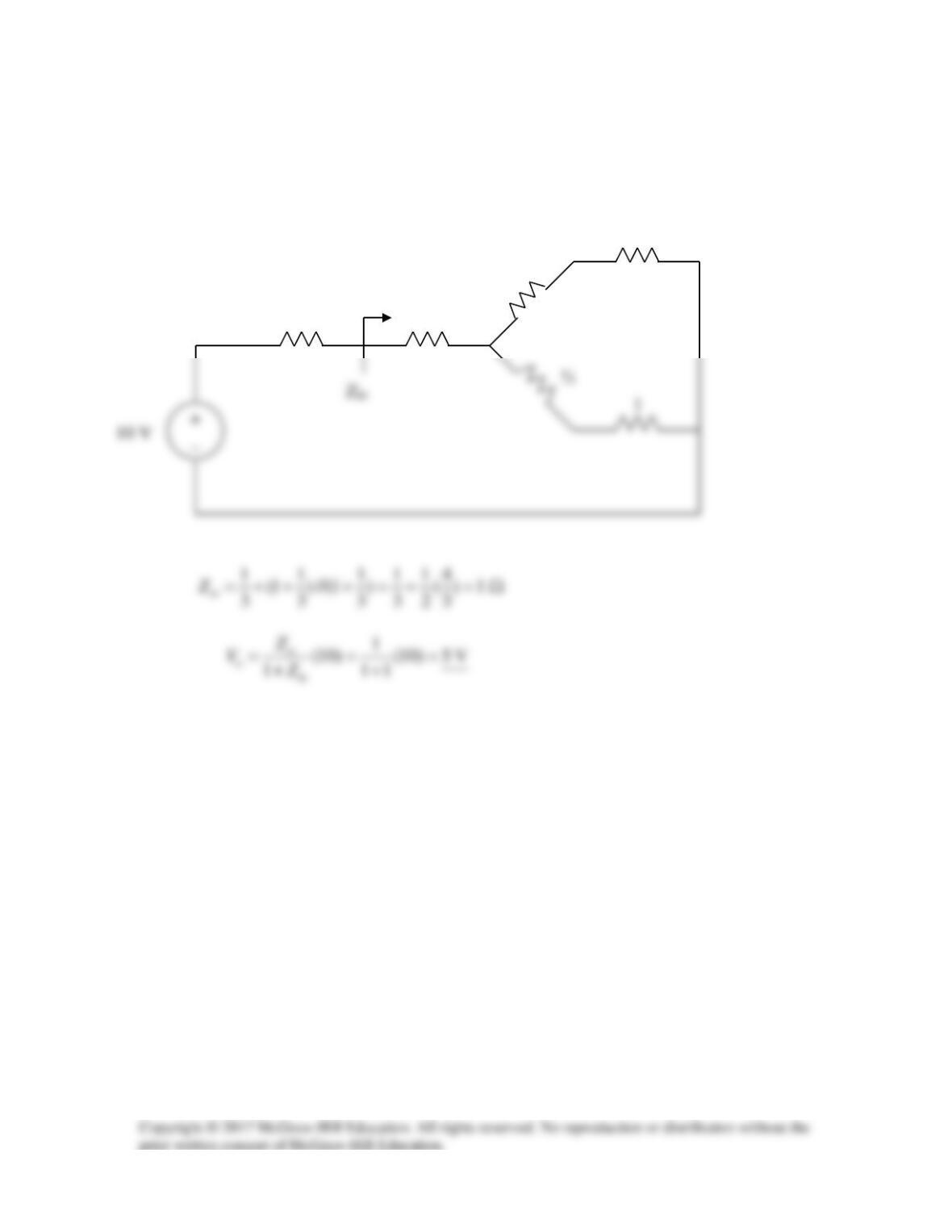
Solution 2.72
Converting the delta subnetwork into wye gives the circuit below.
⅓
1
1
⅓
⅓
1
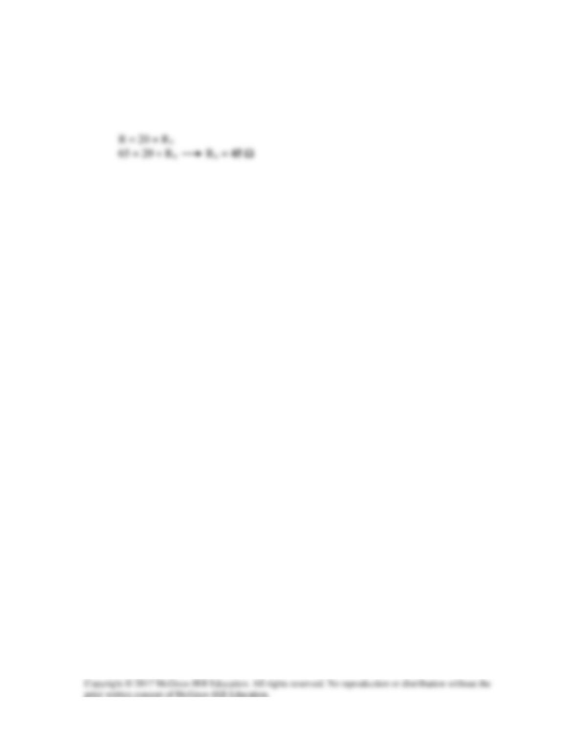
Solution 2.73
By the current division principle, the current through the ammeter will be one-half its
previous value when
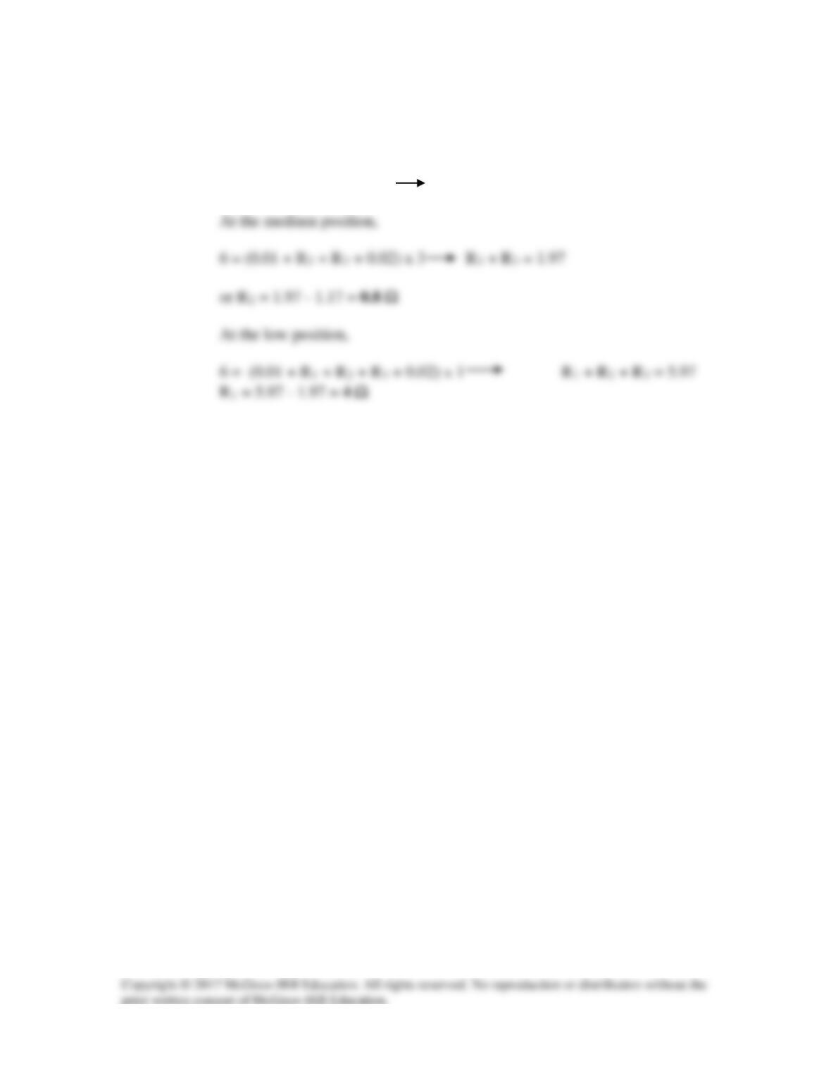
Solution 2.74
With the switch in high position,
6 = (0.01 + R3 + 0.02) x 5 R3 = 1.17 Ω
Solution 2.75
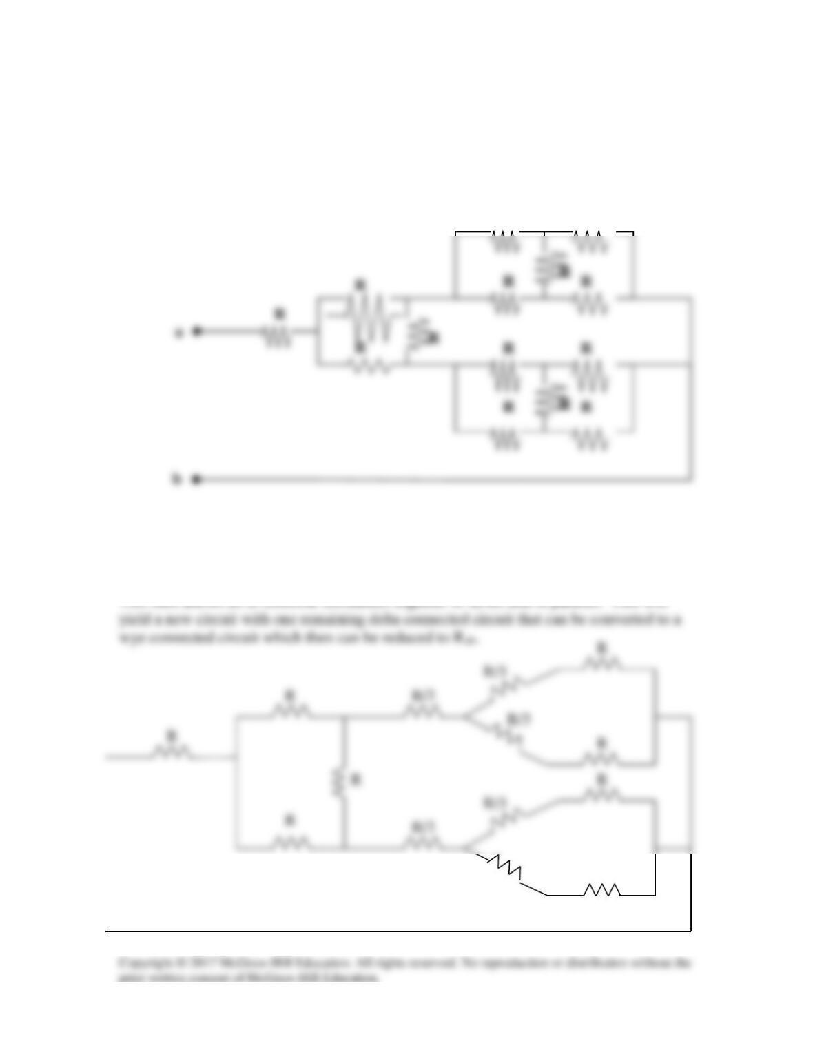
Find Rab in the four-way power divider circuit in Fig. 2.135. Assume each
R = 4 Ω.
Figure 2.135
For Prob. 2.75.
Step 1. There are two delta circuits that can be converted to a wye connected circuit.
R
R
R
R/3
R/3
R/3
R
R/3
R/3
R
R/3
R
R
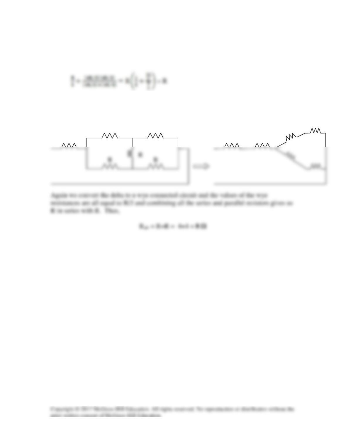
Step 2. Converting delta-subnetworks to wye-subnetworks and combining resistances
leads to the circuit below.
With this combination, the circuit is further reduced to that shown below.
R
R
R
R
R
R

Solution 2.76
Solution 2.77
(a) 5 Ω =
202020201010 =
(b) 311.8 = 300 + 10 + 1.8 = 300 +
8.12020 +
Solution 2.78
The equivalent circuit is shown below:
R
Solution 2.79
Since p = v2/R, the resistance of the sharpener is
Solution 2.80
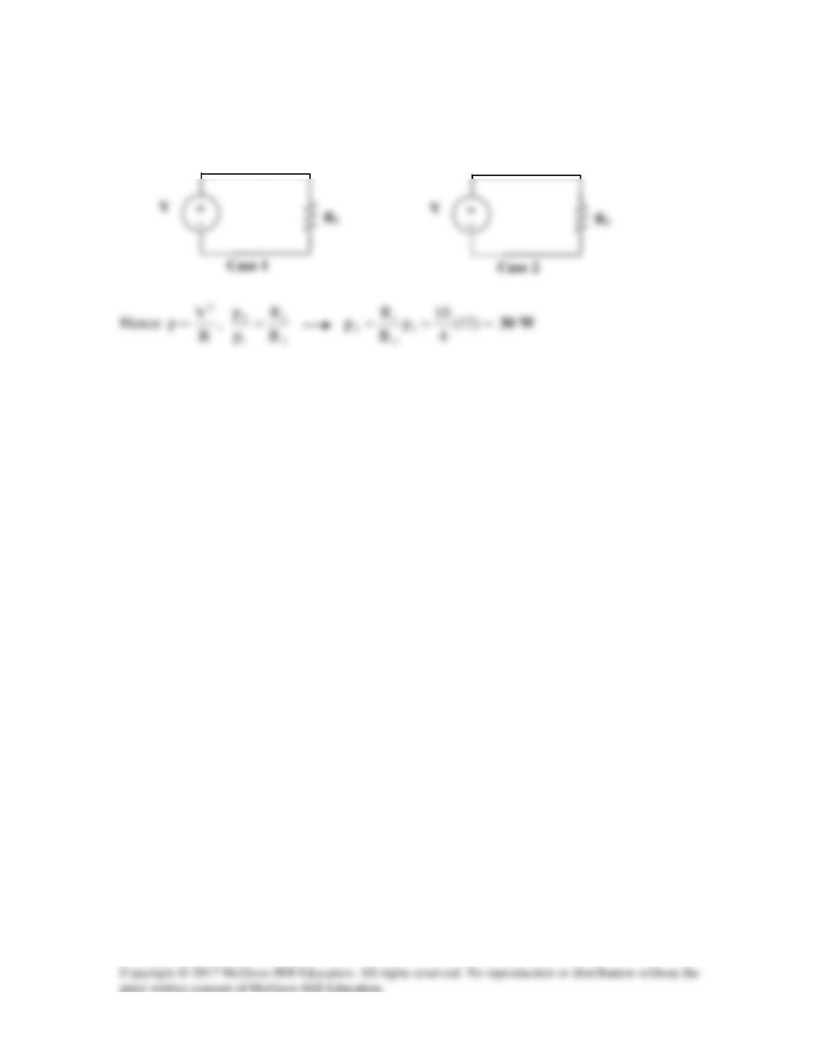
The amplifier can be modeled as a voltage source and the loudspeaker as a resistor:
Solution 2.81
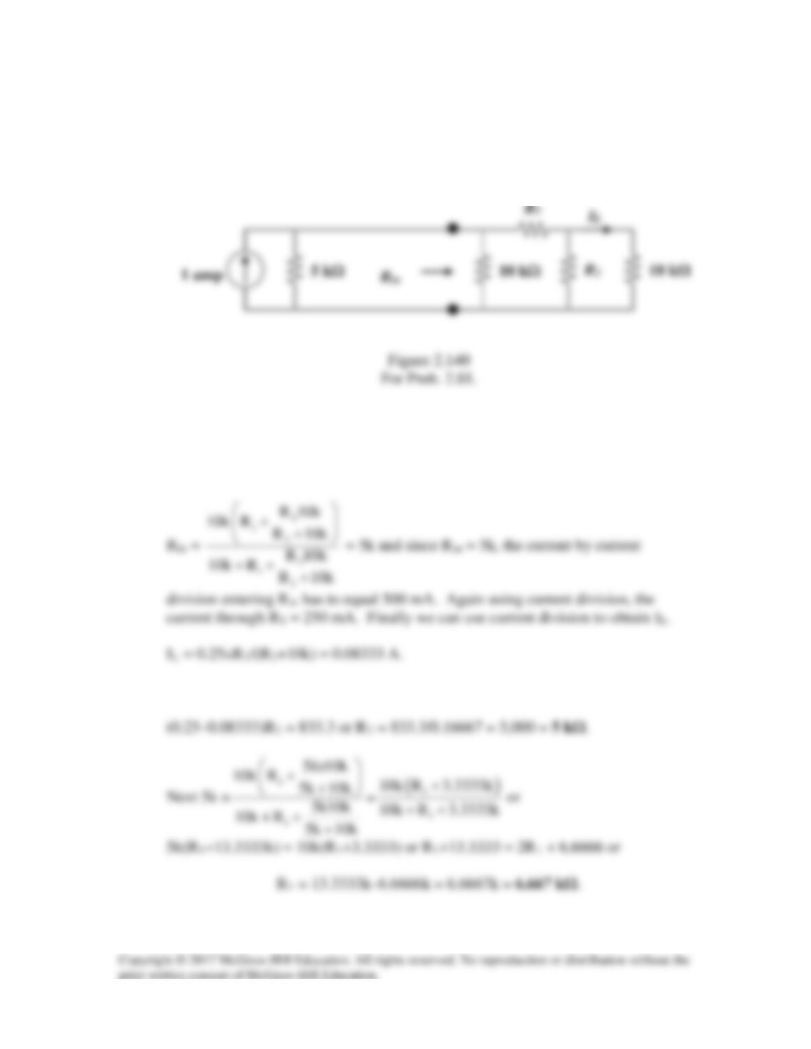
For a specific application, the circuit shown in Fig. 2.140 was designed so that
IL = 83.33 mA and that Rin = 5 kΩ. What are the values of R1 and R2?
Solution
Step 1. Calculate Rin in terms of R1 and R2. Next calculate the value of IL in
terms of R1 and R2.
Step 2. First we can calculate R2. 0.25R2 = 0.08333(R2 + 10,000) or
Solution 2.82
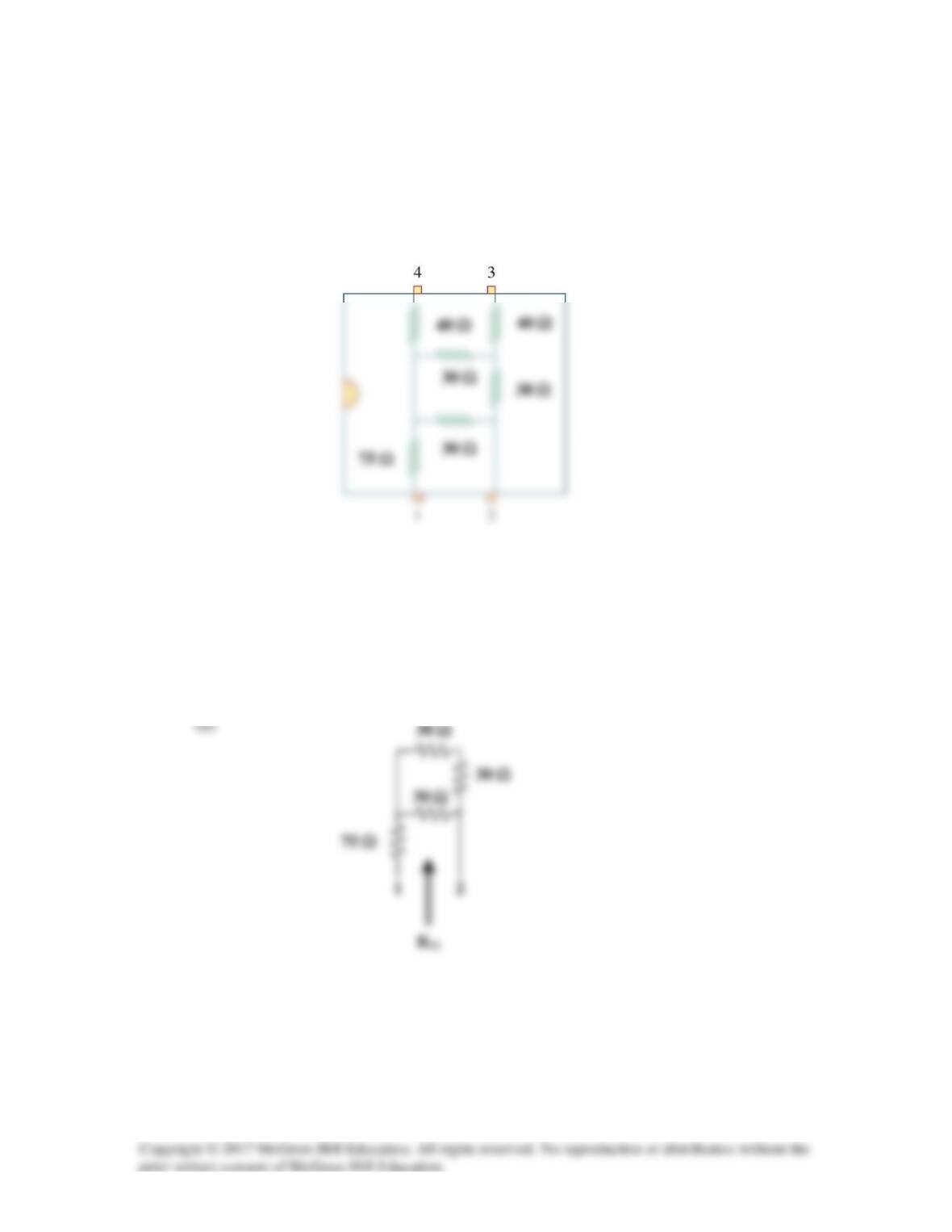
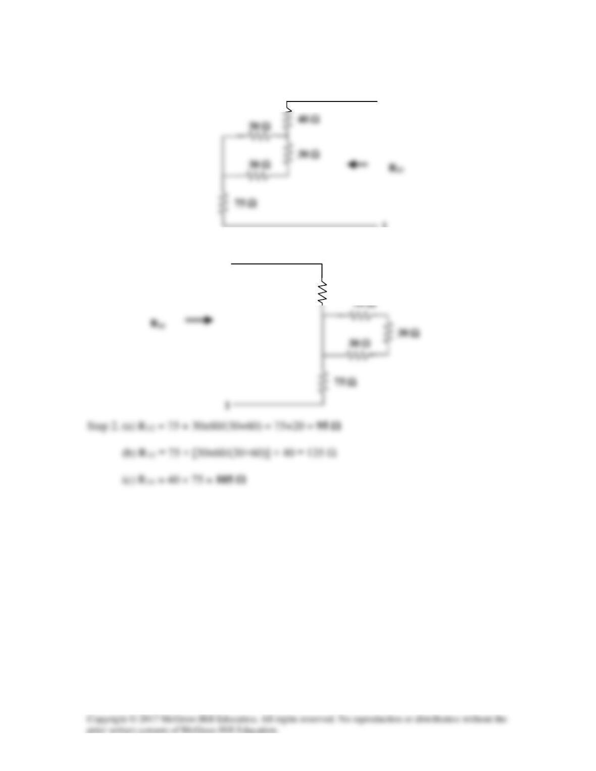
The pin diagram of a resistance array is shown in Fig. 2.141. Find the equivalent
resistance between the following:
(a) 1 and 2 (b) 1 and 3 (c) 1 and 4
Figure 2.141
For Prob. 2.82.
Solution
Step 1. Each pair of contacts will connect a specific circuit where we can use the variety
of wye–delta, series, and paralleling of resistances to obtain the desired results.
(b)
40 Ω
30 Ω
75 Ω
30 Ω
(c)
30 Ω
75 Ω
1
30 Ω
30 Ω
3
1
40 Ω
4
Solution 2.83
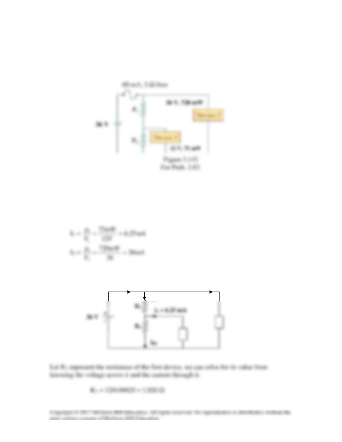
Two delicate devices are rated as shown in Fig. 2.142. Find the values of the resistors
R1 and R2 needed to power the devices using a 36-V battery.
Solution
The voltage across the fuse should be negligible when compared with 24 V (this can be
checked later when we check to see if the fuse rating is exceeded in the final circuit). We
can calculate the current through the devices.
i
i
i2 = 20 mA
i
R1
Ifuse
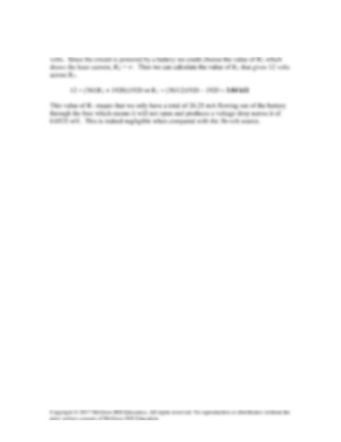
This is an interesting problem in that it essentially has two unknowns, R1 and R2 but only
one condition that need to be met and that is that the voltage across R3 must equal 12