Solution 8.34
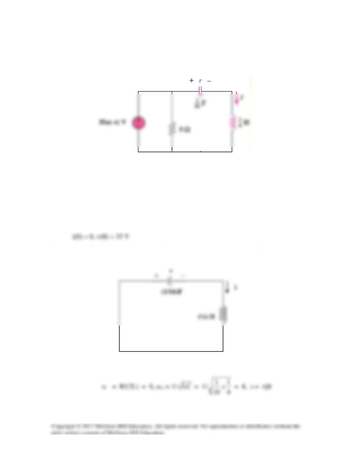
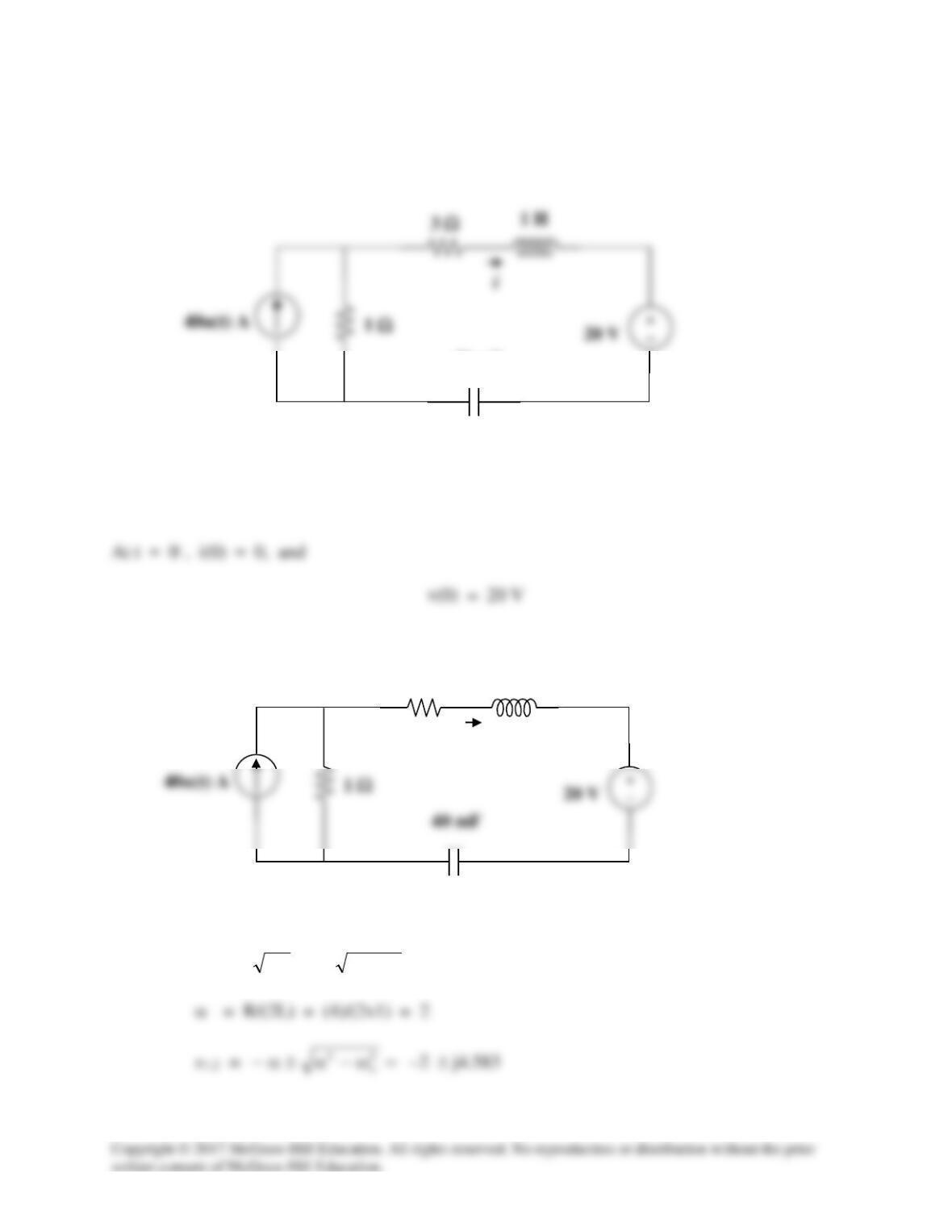
Calculate i(t) for t > 0 in the circuit in Fig. 8.82.
Figure 8.82
For Prob. 8.34.
Solution
Before t = 0, the capacitor acts like an open circuit while the inductor behaves like a short
circuit.
For t > 0, the LC circuit is disconnected from the voltage source as shown below.
This is a lossless, source–free, series RLC circuit.
Since α is equal to zero, we have an undamped response. Therefore,
Solution 8.35
Using Fig. 8.83, design a problem to help other students to better understand the step response of
series RLC circuits.
Problem
Determine v(t) for t > 0 in the circuit in Fig. 8.83.
Figure 8.83
Solution
For t > 0, we have a series RLC circuit with a step input.
α = R/(2L) = 2/2 = 1, ωo = 1/
LC
= 1/
5/1
= 5
Solution 8.36
Obtain v(t) and i(t) for t > 0 in the circuit in Fig. 8.84.
Figure 8.84
For Prob. 8.36.
Solution
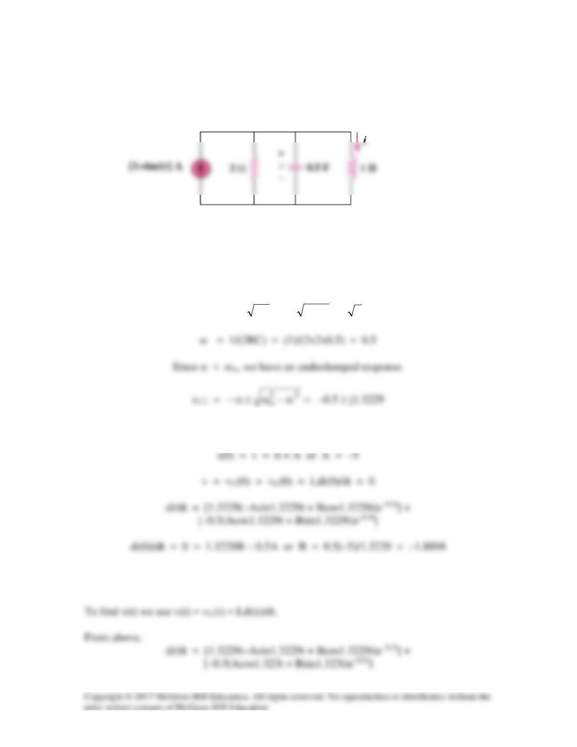
For t > 0, we have the series RLC circuit shown below.
2 Ω
40 V
α = R/(2L) = (2 + 2 + 4)/(2×5) = 0.8
4 Ω
i
2 Ω
5 H
i(0) = Cdv(0)/dt = 0
But dv/dt = [–0.8(Acos(0.6t) + Bsin(0.6t))e–0.8t] + [0.6(–Asin(0.6t) + Bcos(0.6t))e–0.8t]
Solution 8.37
For the network in Fig. 8.85, solve for i(t) for t > 0.
Figure 8.85
For Prob. 8.37.
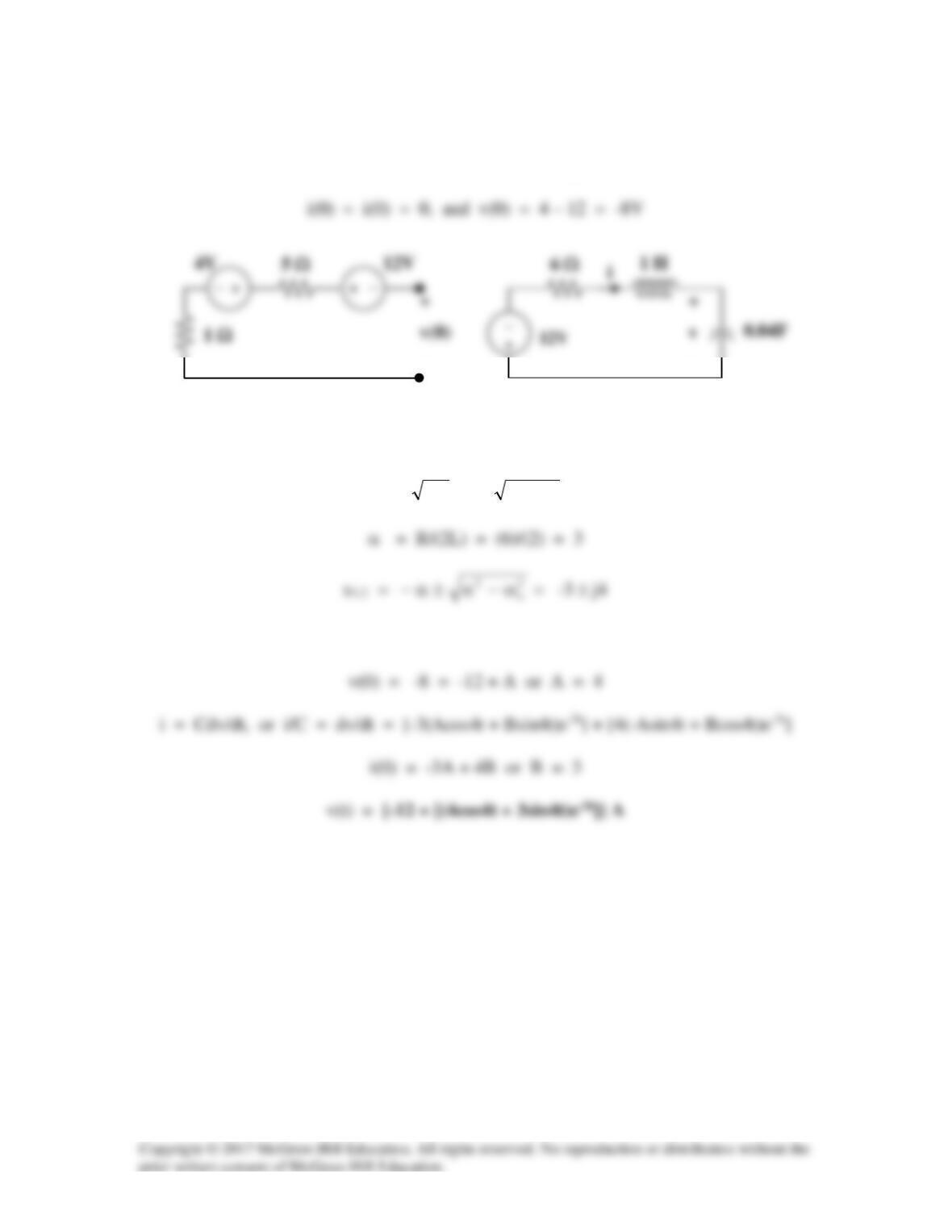
Solution
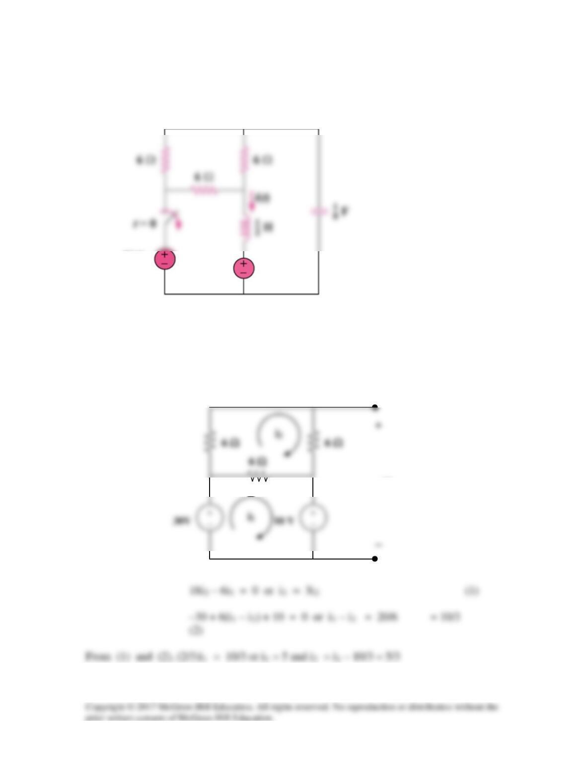
For t = 0–, the equivalent circuit is shown below.
v(0)
10 V
30 V
i(0) = i1 = 5A
For t > 0, we have a series RLC circuit.
R = 6||12 = 4
α = ωo, therefore the circuit is critically damped
To find iC(0) we need to look at the circuit right after the switch is opened. At this time,

iC = Cdv/dt = (1/8)[–4(10 + 0t)e–4t] + (1/8)[(0)e–4t]
Solution 8.38
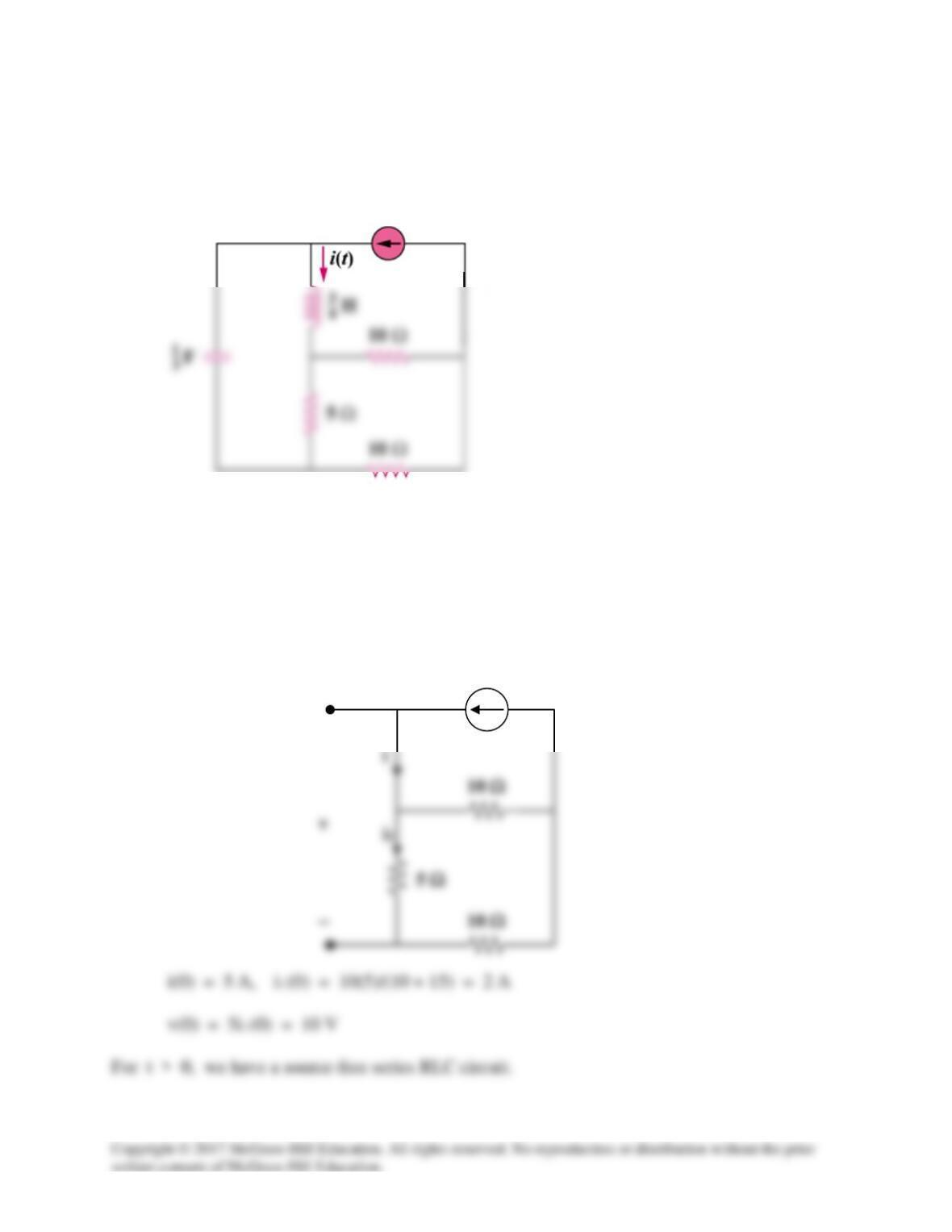
Refer to the circuit in Fig. 8.86. Calculate i(t) for t > 0.
Figure 8.86
For Prob. 8.38.
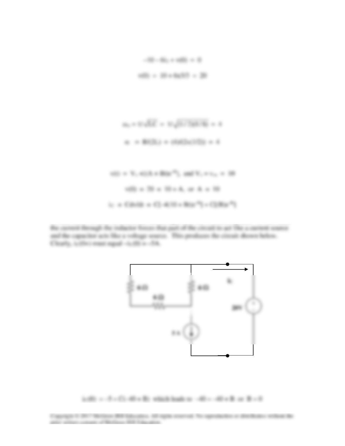
Solution
At t = 0—, the equivalent circuit is as shown.
i
+
5 A
5[1 – u(t)] A
R = 5||(10 + 10) = 4 ohms
Solution 8.39
Determine v(t) for t > 0 in the circuit in Fig. 8.87.
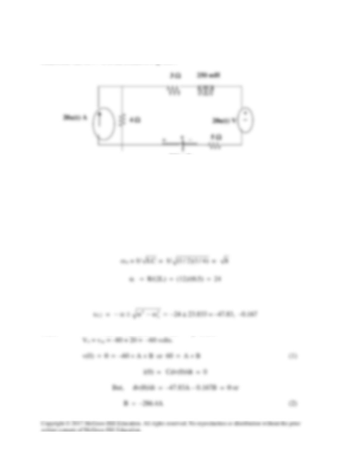
Figure 8.87
For Prob. 8.39.
Solution
For t = 0–, the source voltages are equal to zero thus, the initial conditions are v(0) = 0 and
iL(0) = 0.
For t > 0,
R = 3 + 5 + 4 = 12 ohms
Since α > ωo, we have an overdamped response.
Thus, v(t) = Vs + [Ae–47.83t + Be–0.167t], where
500 mF

Solution 8.40
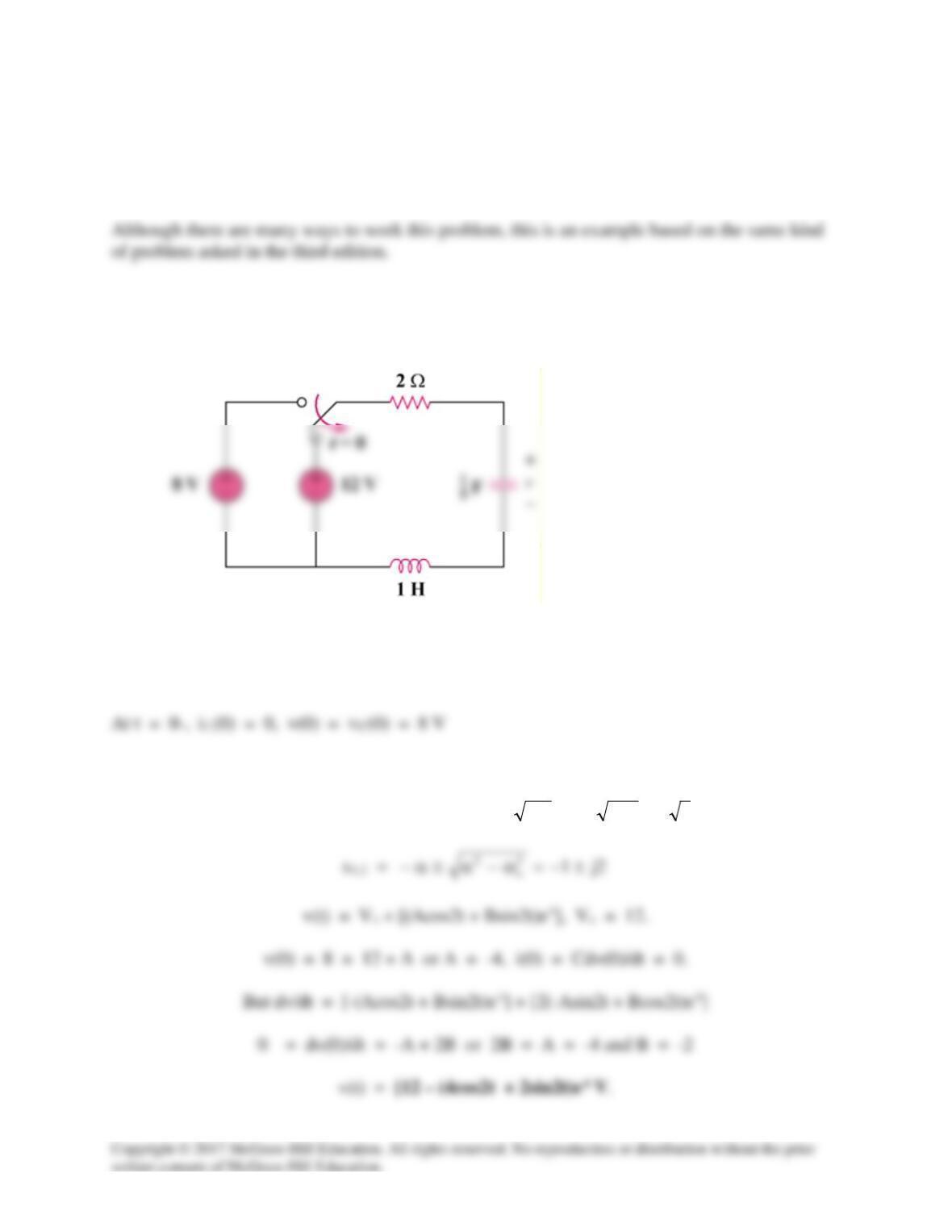
The switch in the circuit of Fig. 8.88 is moved from position a to b at t = 0. Assume that
the voltage across the capacitor is equal to zero at t = 0 and that the switch is a make
before break switch. Determine i(t) for t > 0.
Figure 8.88
For Prob. 8.40.
Solution
For t > 0, we have a series RLC circuit with a step input as shown below.
Since α = ωo, we have a critically damped response.
14 Ω
i
2 H
0.02 F
+ −
v
v(0) = 0 = 18 + A or A = –18.
Solution 8.41
For the network in Fig. 8.89, find i(t) for t > 0.
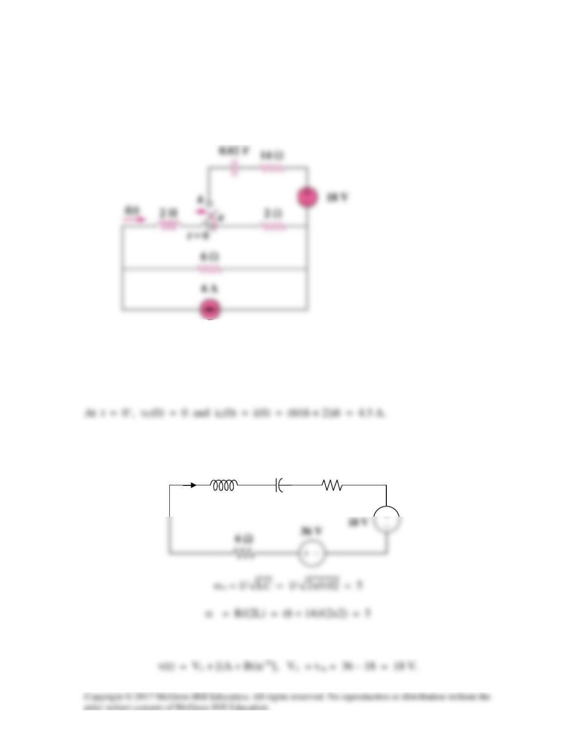
Figure 8.89
For Prob. 8.41.
Solution
For t > 0, we have a series RLC circuit shown below.
40 mF
ωo = 1/
LC
= 1/
25/1x1
= 5 rad/sec
40 mF
+ −
v
i
1 H
3 Ω
Thus, v(t) = Vss + [(Acos(ωdt) + Bsin(ωdt))e–2t],
i(0) = 0 = 2A – ωdB
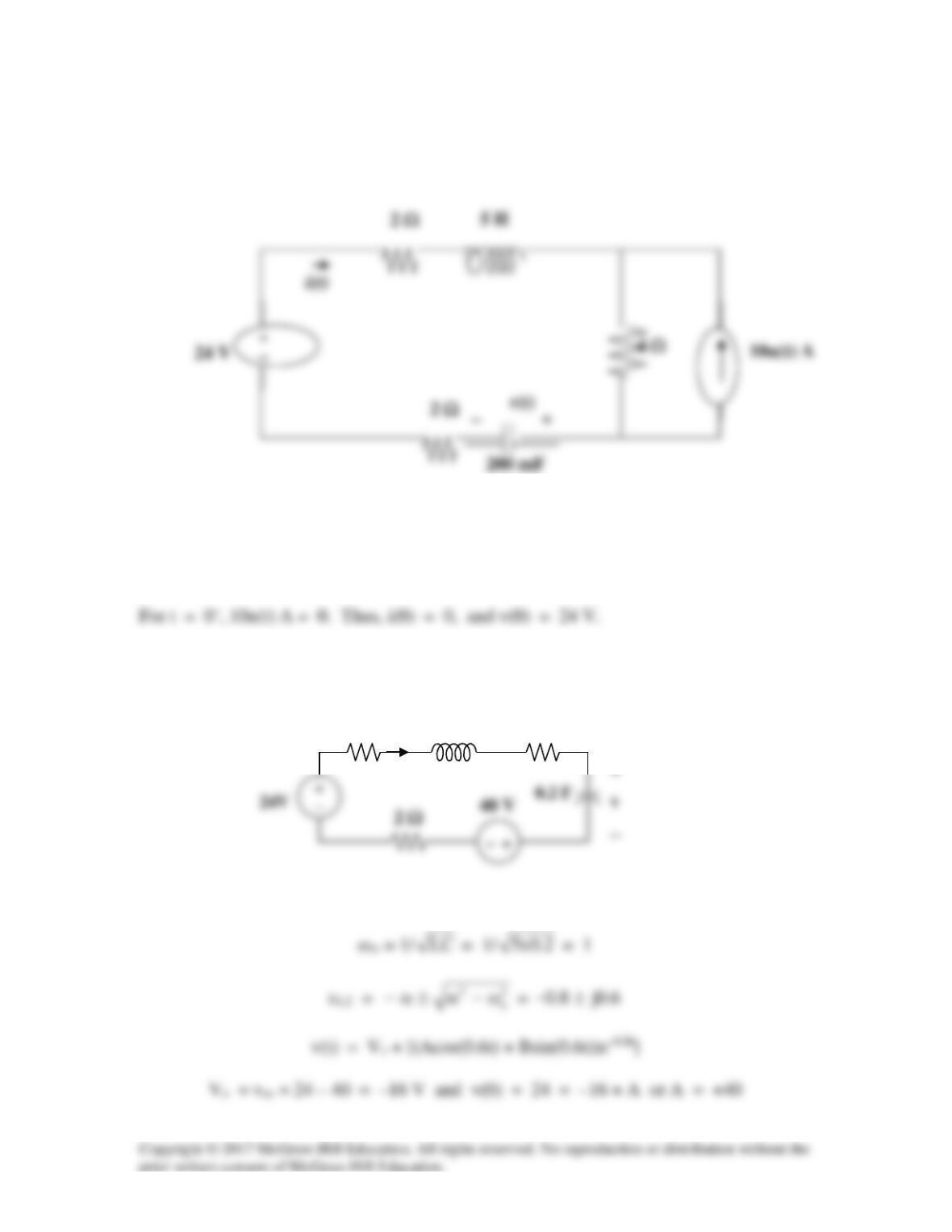
Solution 8.42
For t = 0-, we have the equivalent circuit as shown in Figure (a).
For t > 0, the circuit becomes that shown in Figure (b) after source transformation.
ωo = 1/
LC
= 1/
25/1x1
= 5
Thus, v(t) = Vs + [(Acos4t + Bsin4t)e–3t], Vs = -12
(a)
−
(b)
−
Solution 8.43
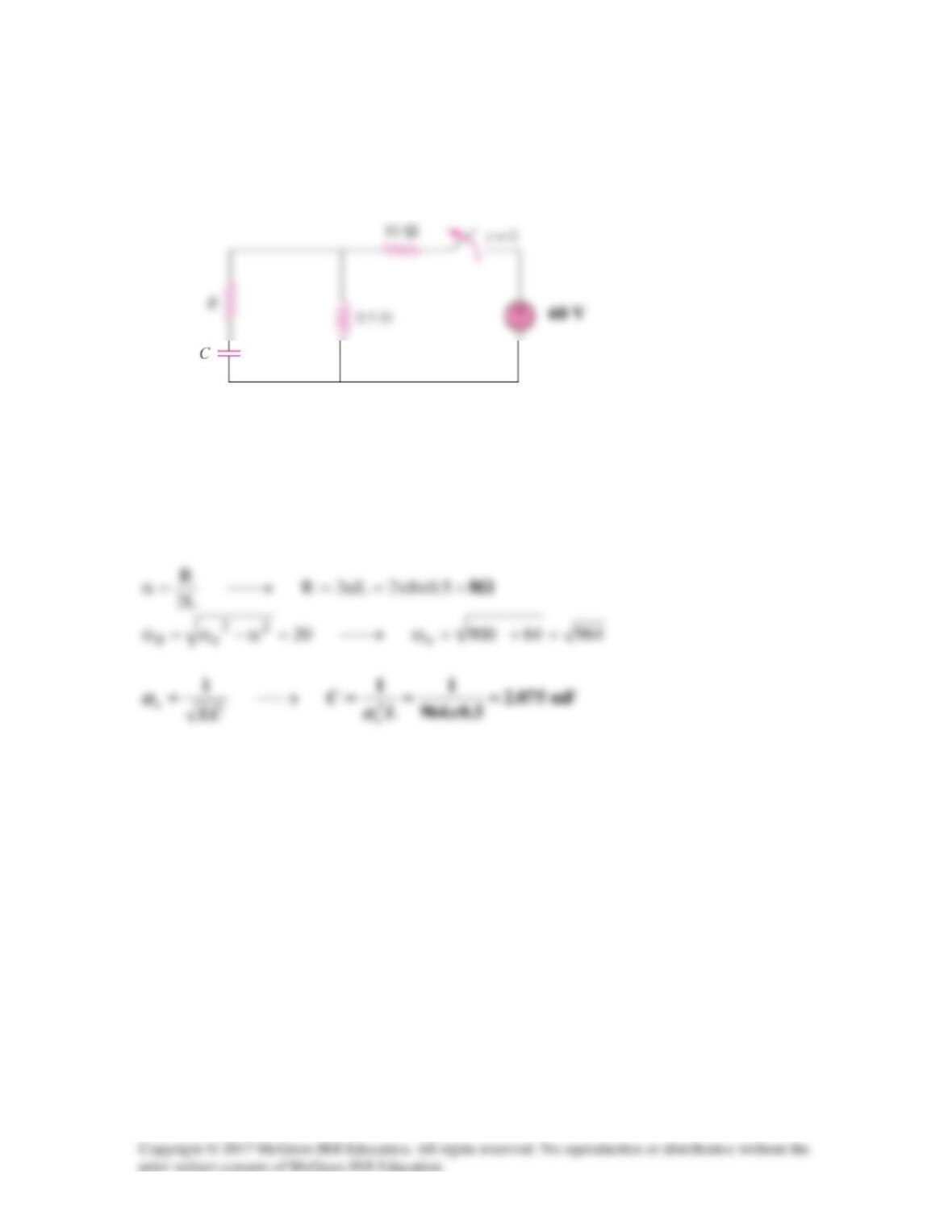
The switch in Fig. 8.91 is opened at t = 0 after the circuit has reached steady state.
Choose R and C such that
α
= 8 Np/s and
ω
d = 30 rad/s.
Figure 8.91
For Prob. 8.43.
Solution
For t>0, we have a source-free series RLC circuit.
Solution 8.44
Solution 8.45
In the circuit of Fig. 8.92, find v(t) and i(t) for t > 0.
Figure 8.92
For Prob. 8.45.
Solution
ωo = 1/
LC
= 1/
5.0x1
=
2
Thus, i(t) = Is + [(Acos1.3229t + Bsin1.3229t)e–0.5t], Is = 6
Thus, i(t) = {6 – [(5cos1.3229t + 1.8898sin1.3229t)e–t/2]} A