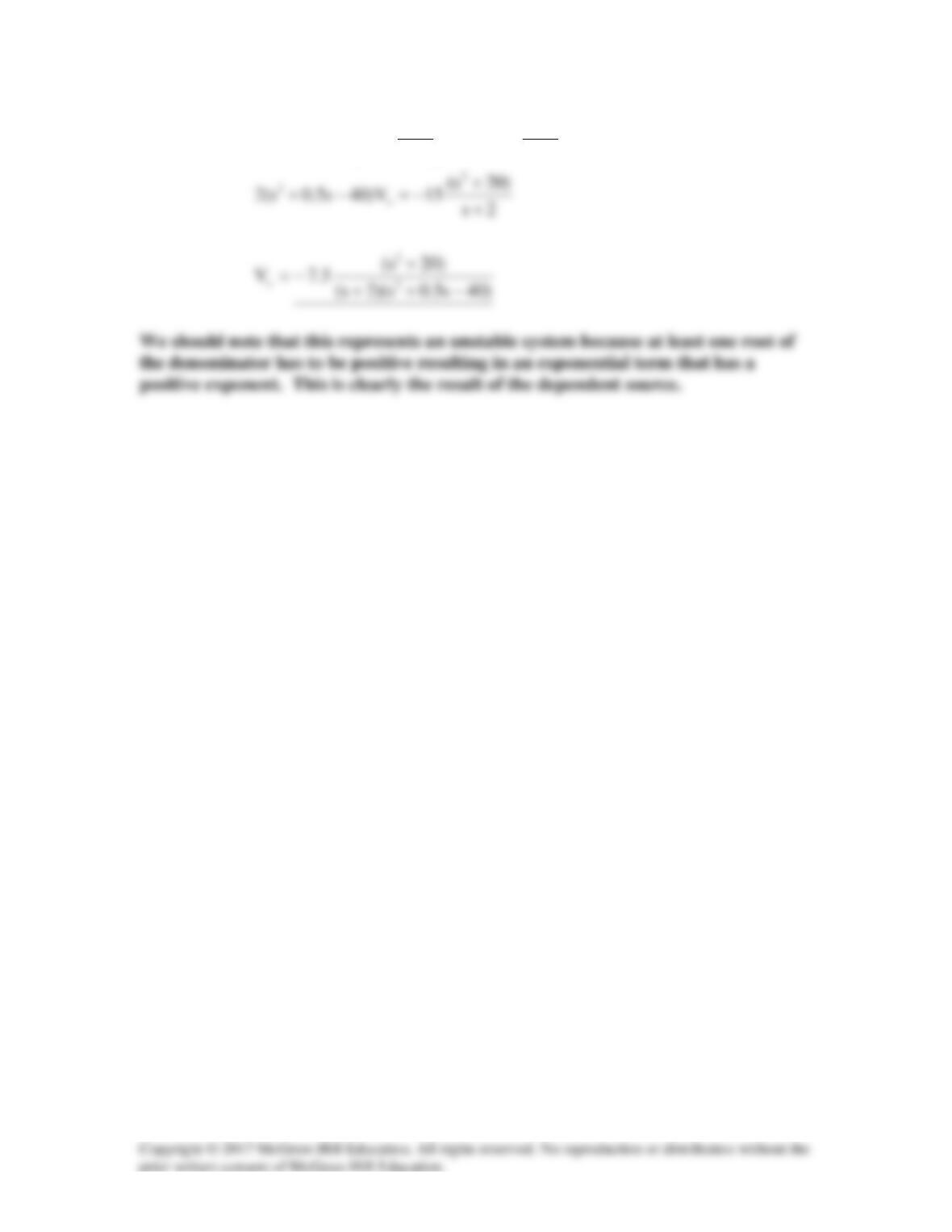
0
2s
s5.7
V120
2s
5.7
V)40ss2(
xx
2
=
+
−−
+
+++
Solution 16.49
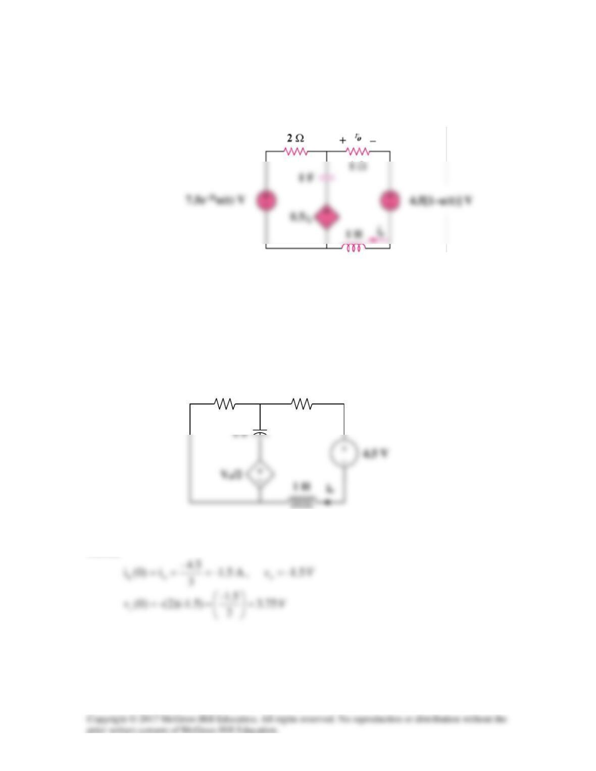
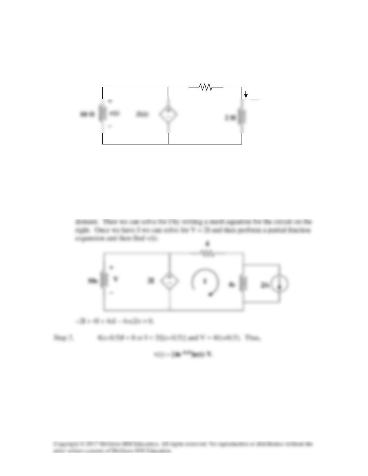
Find io(t) for t > 0 in the circuit in Fig. 16.72.
Figure 16.72
For Prob. 16.49.
Solution
We first need to find the initial conditions. For
0t <
, the circuit is shown in Fig. (a).
To dc, the capacitor acts like an open circuit and the inductor acts like a short circuit.
Hence,
(a)
2 Ω
+ −
Vo
1 Ω
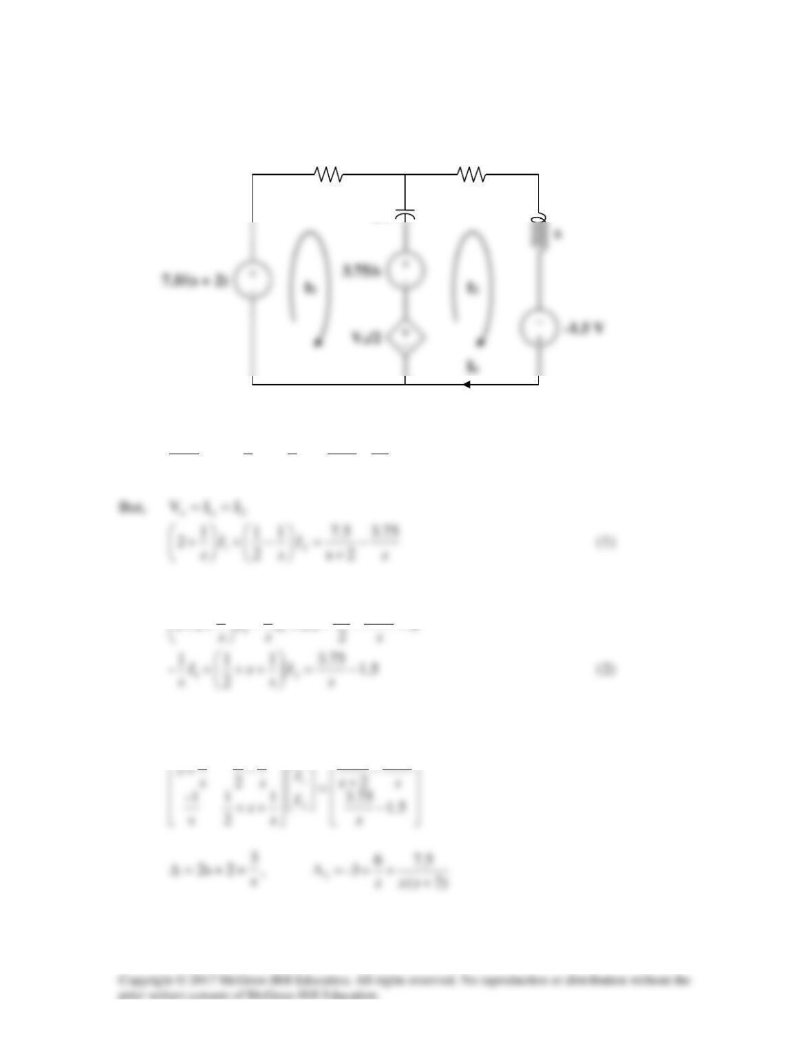
We now incorporate the initial conditions and transform the circuit into the s-domain.
For mesh 1,
0
2
75.311
2
2s
7.5–
21
=++−
++
+
o
V
s
I
s
I
s
For mesh 2,
75.3
11
++
V
Put (1) and (2) in matrix form.
75.3
5.7
1
11
(b)
2
1/s
+ −
Vo
1
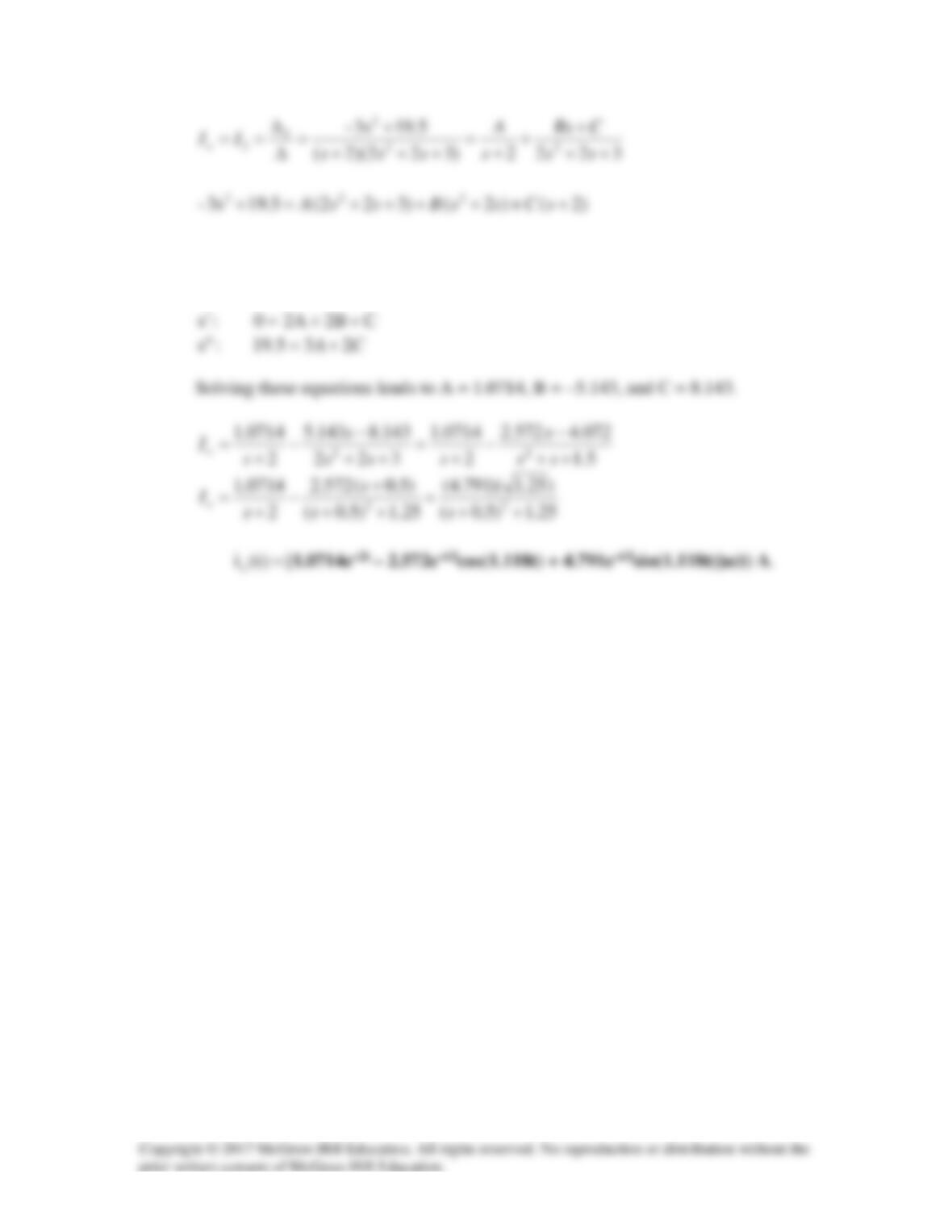
Equating coefficients :
2
s
:
BA += 23–
Solution 16.50
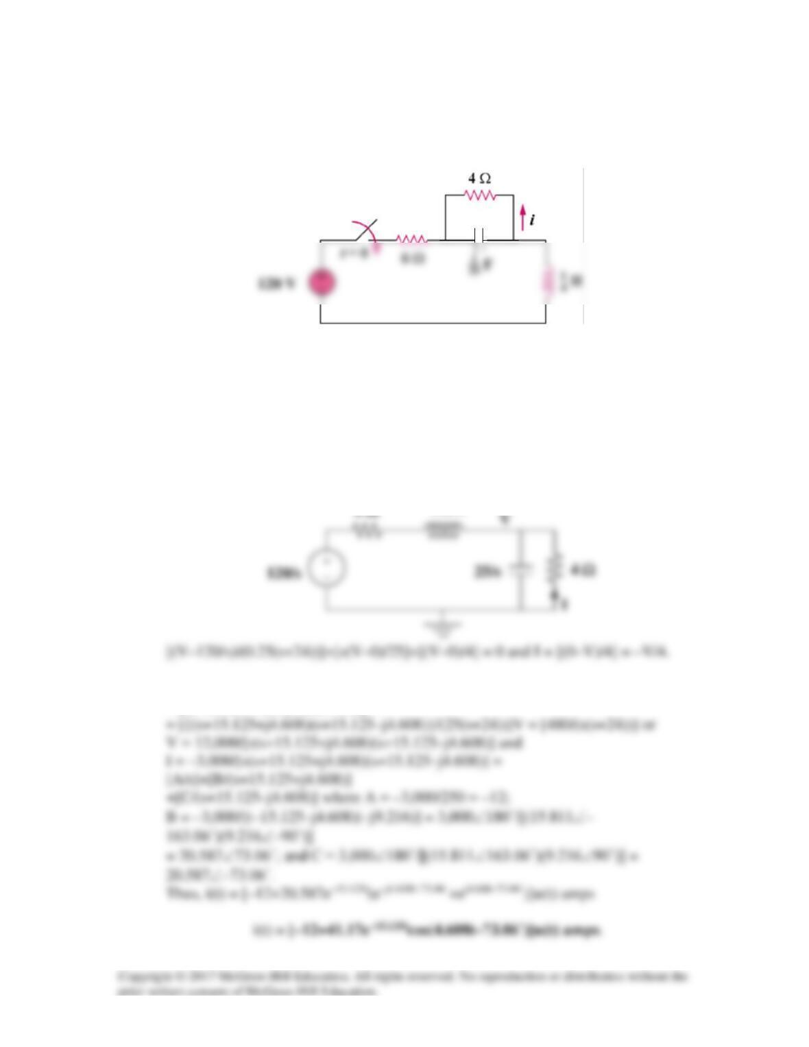
For the circuit in Fig. 16.73, find v(t) for t > 0. Assume that i(0) = 2 A.
Figure 16.73
For Prob. 16.50.
Solution
Step 1. This is an interesting problem in that we can neglect the left hand side of
the circuit in that it is in parallel with an ideal voltage source even though it is a
dependent source. The first thing to do is to transform the circuit into the s-
2 Ω
i(t)
0.25s
6 Ω
Solution 16.51
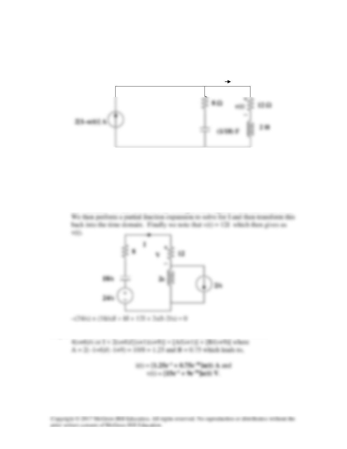
In the circuit of Fig. 16.74, find i(t) for t > 0.
Figure 16.74
For Prob. 16.51.
Solution
Step 1. First we note that the initial conditions for the capacitor and inductor have
to be equal to zero. Next we simplify the circuit and then convert the circuit into
the s-domain and solve for V. Then we can solve for I and then perform a partial
fraction expansion and convert I back into the time domain.
Step 2. [(4/(s+24))+(s/25)+0.25]V = [(s2+24s+6.25s+100+150)/(25(s+24))]V
= [(s2+30.25s+250)/(25(s+24))]V
Solution 16.52
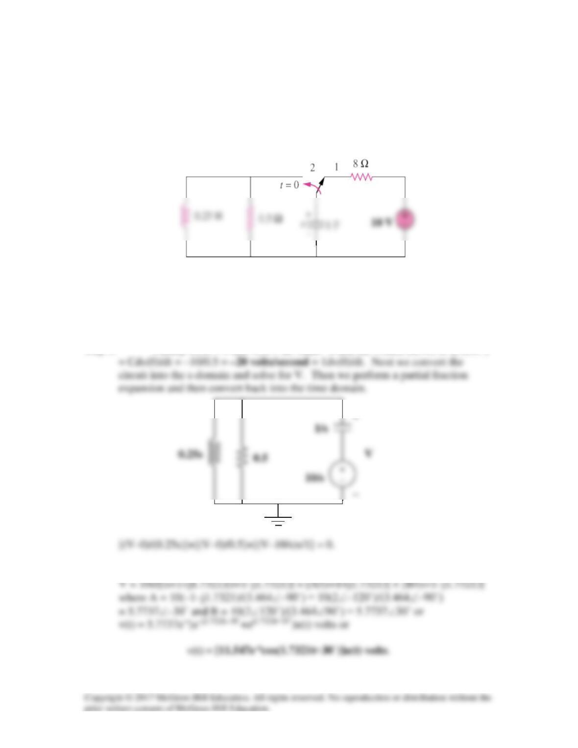
Given the circuit shown in Fig. 16.75, determine the values for i(t) and v(t) for all t > 0.
Figure 16.75
For Prob. 16.52.
Solution
Step 1. First we determine the initial conditions and then transform the circuit into
the s-domain. We can solve for I by writing a mesh equation and then solve for I.
Step 2. [(18/s)+8+12+2s]I = 2[s+10+(9/s)]I = 2[(s2+10s+9)/s]I = 4+24/s =
i(t)
Solution 16.53
In the circuit of Fig. 16.76, the switch has been in position 1 for a long time but moved to
position 2 at t = 0. Find:
(a) v(0+), dv(0+)/dt
(b) v(t) for t ≥ 0.
Figure 16.76
For Prob. 16.53.
Solution
Step 1. Clearly iL(0) = 0 and v(0) = 10 volts. When the switch moves to 2, iC(0+)
Step 2. [(4/s)+2+s]V = [(s2+2s+4)/s]V = 10 or
Solution 16.54
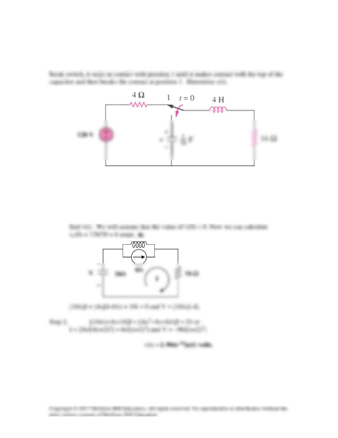
The switch in Fig. 16.77 has been in position 1 for t < 0. At t =0, it is moved from
position 1 to the top of the capacitor at t = 0. Please note that the switch is a make before
Figure 16.77
For Prob. 16.54.
Solution
Step 1. First determine the initial conditions and then transform the circuit into the
s-domain and solve for V. Then perform a partial fraction expansion and then
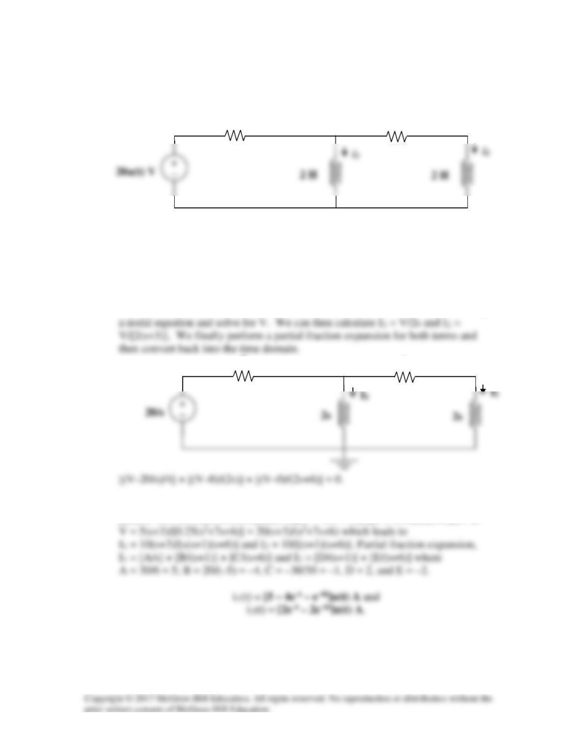
2s
4
6
V
Solution 16.55
Obtain i1 and i2 for t > 0 in the circuit of Fig. 16.78.
Figure 16.78
For Prob. 16.55.
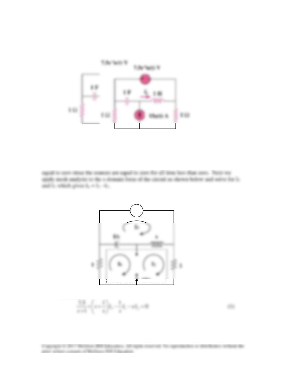
Solution
Step 1. Since the independent source is equal to zero for all t < 0, there will not be
any initial conditions. We then transform the circuit into the s-domain and set up
Step 2. [0.25+(0.5/s)+0.5/(s+3)]V = 5/s or
[(0.25s2+0.75s+0.5s+1.5+0.5s)/(s(s+3))]V = 5/s = 0.25[(s2+7s+6)/(s(s+3))]V or
4 Ω
6 Ω
Solution 16.56
Calculate io(t) for t > 0 in the network of Fig. 16.79.
Figure 16.79
For Prob. 16.56.
Solution
Step 1. First we need to determine the initial conditions which in this case are
For mesh 3,
7.5/(s+1)
+ −
15/s
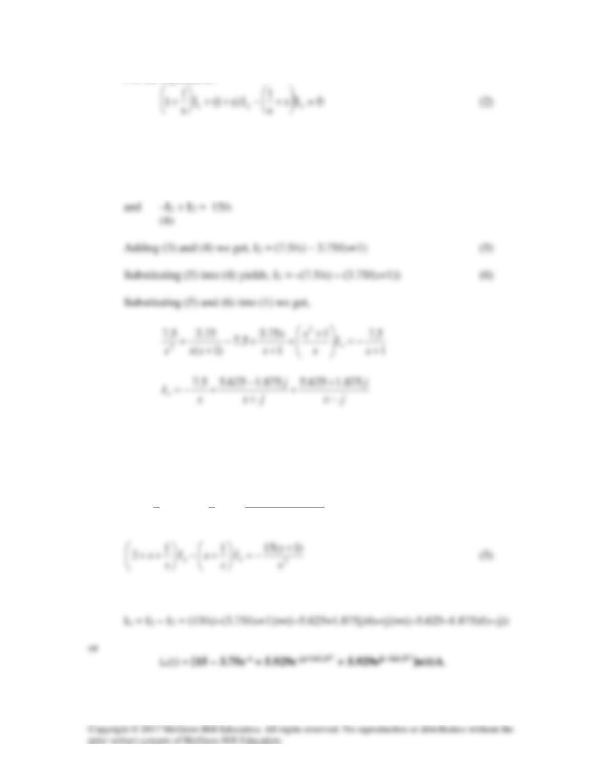
For the supermesh,
Step 2. Adding (1) and (2) we get, I1 + I2 = –7.5/(s+1) (3)
Substituting (3) into (1) and (2) leads to
)1(
)22(5.711
–
2
2
32
+
++−
=
++
+
ss
ss
I
s
sI
s
s
(4)
We can now solve for Io.
Solution 16.57
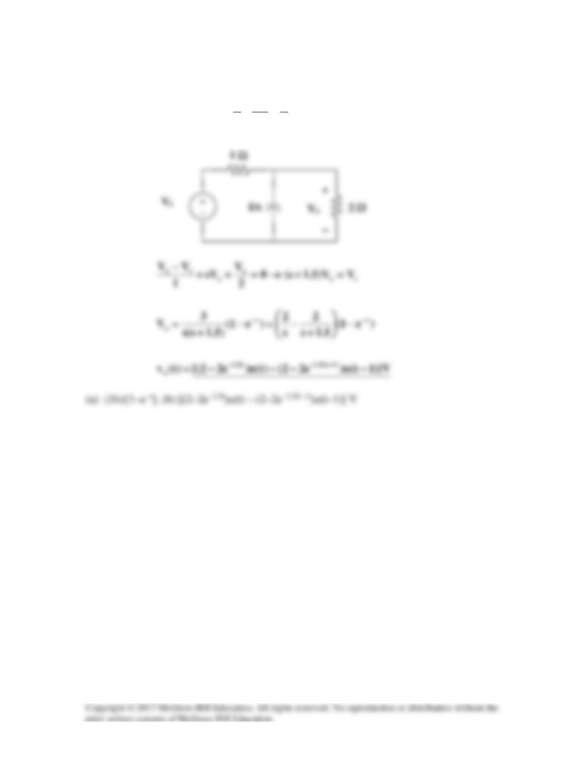
vs(t) = 3u(t) – 3u(t–1) or Vs =
)e1(
s
3
s
e
s
3
s
s−
−
−=−
Solution 16.58
Using Fig. 16.81, design a problem to help other students to better understand circuit
analysis in the s-domain with circuits that have dependent sources.
Although there are many ways to solve this problem, this is an example based on the
same kind of problem asked in the third edition.
Problem
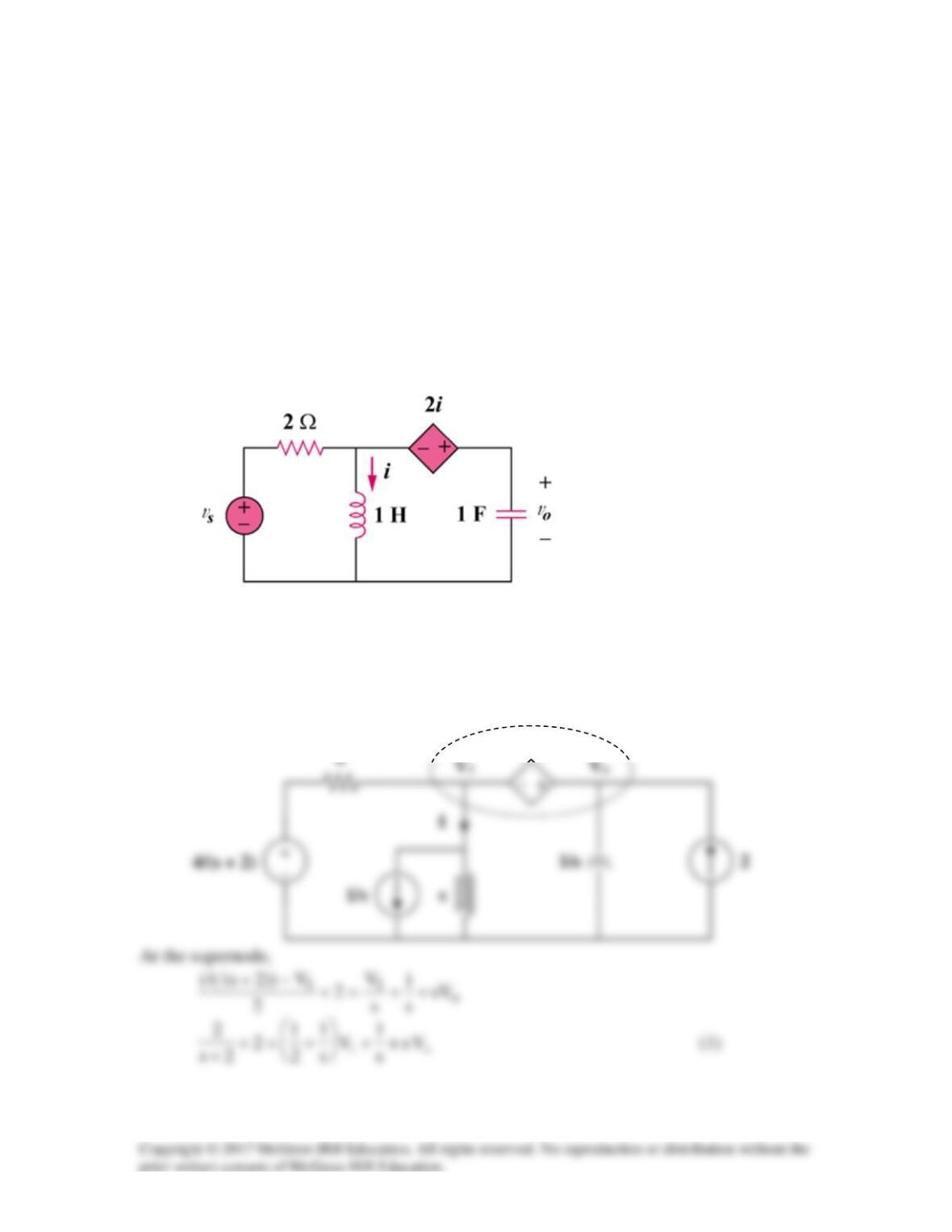
In the circuit of Fig. 16.81, let i(0) = 1 A, vo(0) = 2 V, and vs = 4 e-2t u(t) V. Find vo(t)
for t > 0.
Figure 16.81
For Prob. 16.58.
Solution
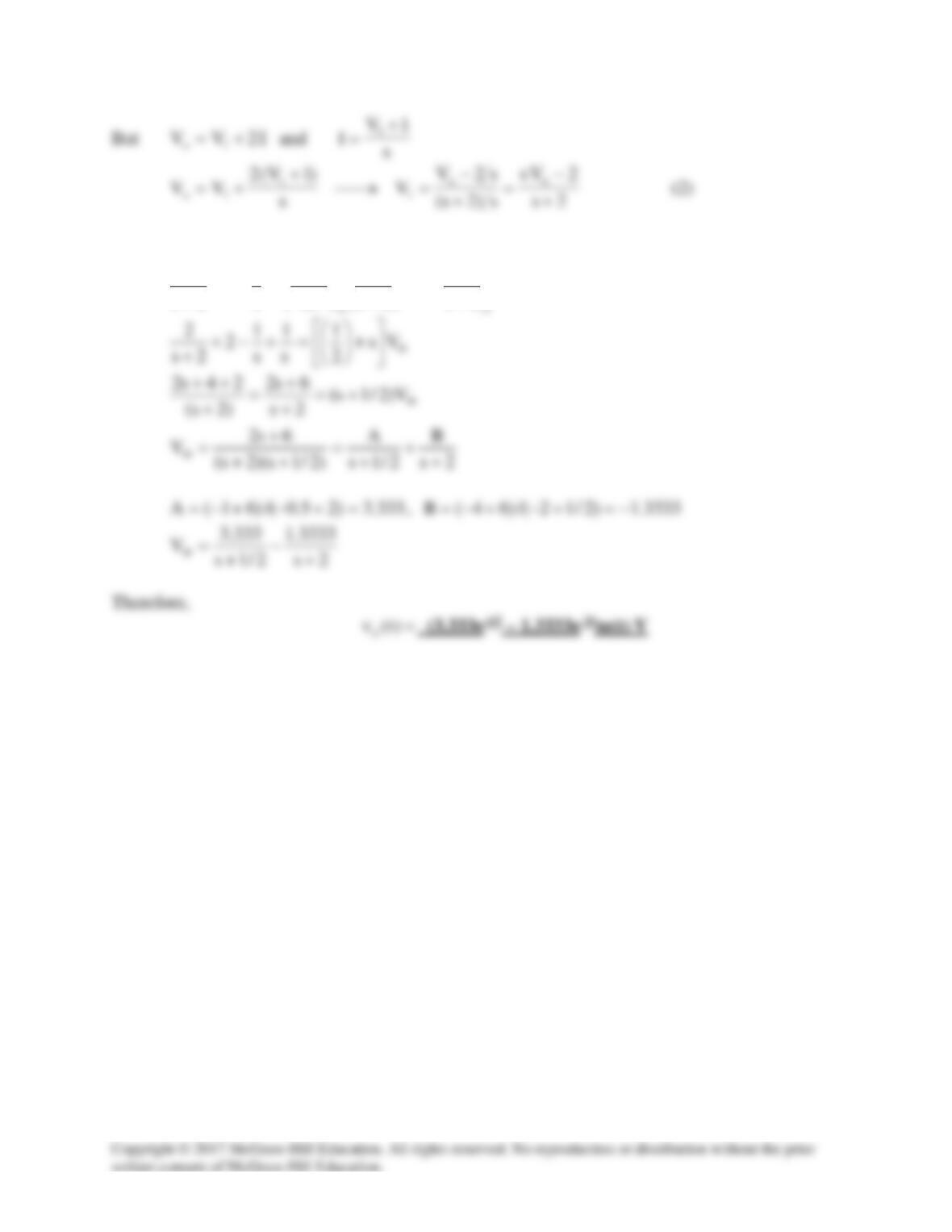
We incorporate the initial conditions in the s-domain circuit as shown below.
2 I
Substituting (2) into (1)
oo Vs
2s
2
V
2s
s
s2
2s
s
1
2
2s
2+
+
−
+
+
=−+
+
Solution 16.59
Find vo(t) in the circuit in Fig. 16.82 if vx(0) = 10 V and i(0) = 5 A.
Figure 16.82
For Prob. 16.59.
Solution
Step 1. We incorporate the initial conditions and transform the current source to a
voltage source as shown and then convert the circuit into the s-domain.
At the main non-reference node, KCL gives
Step 2.
s
s
VssVs
s
s
oo
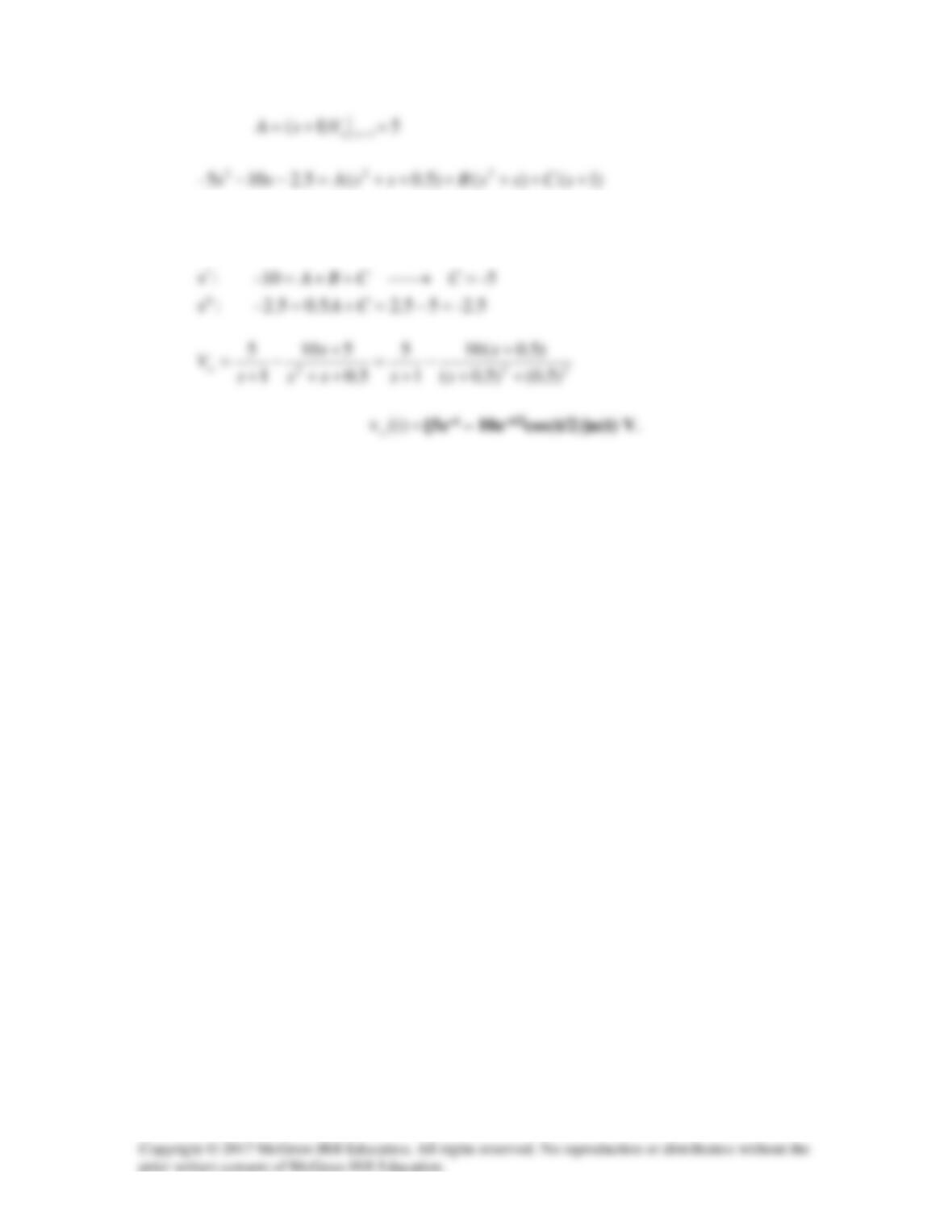
)1(5
))1(1)(1(10
1
5+
+++=−−
+
Equating coefficients :
2
s
:
-105– =→+= BBA
0
s
Solution 16.60
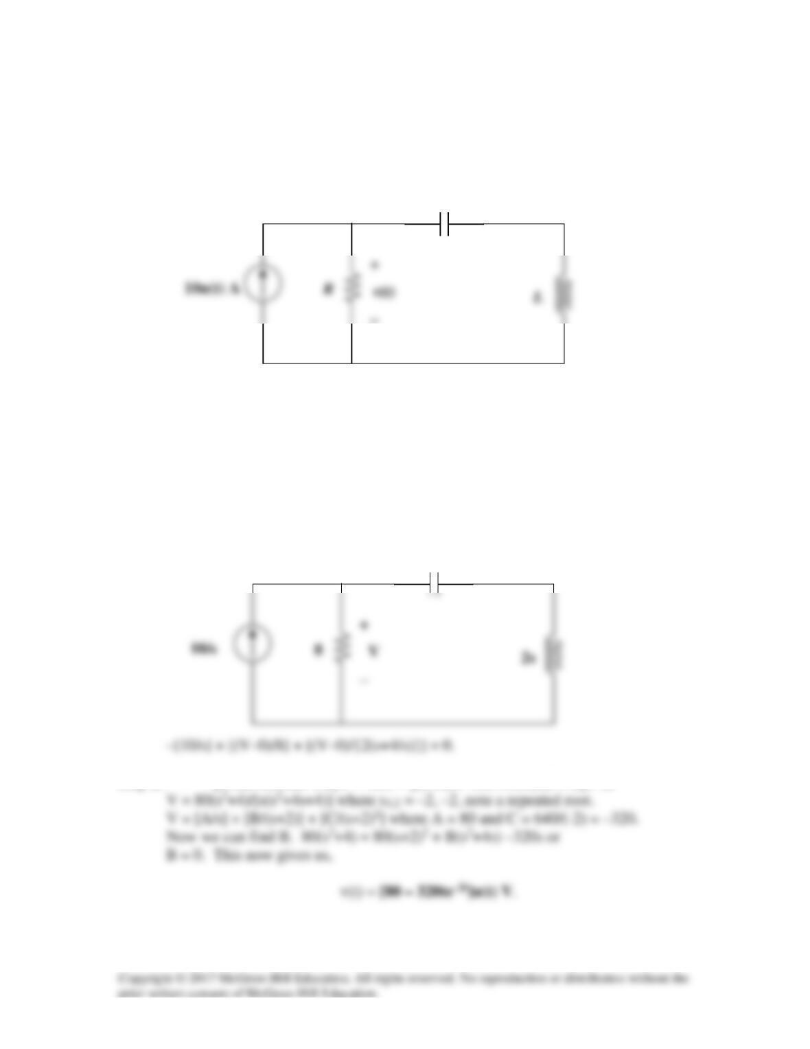
Find the response v(t) for t > 0 in the circuit in Fig. 16.83. Let R = 8 Ω, L = 2 H, and
C = 125 mF.
R
Figure 16.83
For Prob. 16.60.
Solution
Step 1. The first thing is to note that there are no initial conditions since the source
= 0 for all t < 0. Next we transform the circuit into the s-domain and write one
nodal equation and solve for V. The we perform a partial fraction expansion and
solve for v(t).
Step 2. [0.125+0.5s/(s2+4)]V = 10/s = [(0.125s2+0.5+0.5s)/(s2+4)]V or
C
−
8/s
Solution 16.61
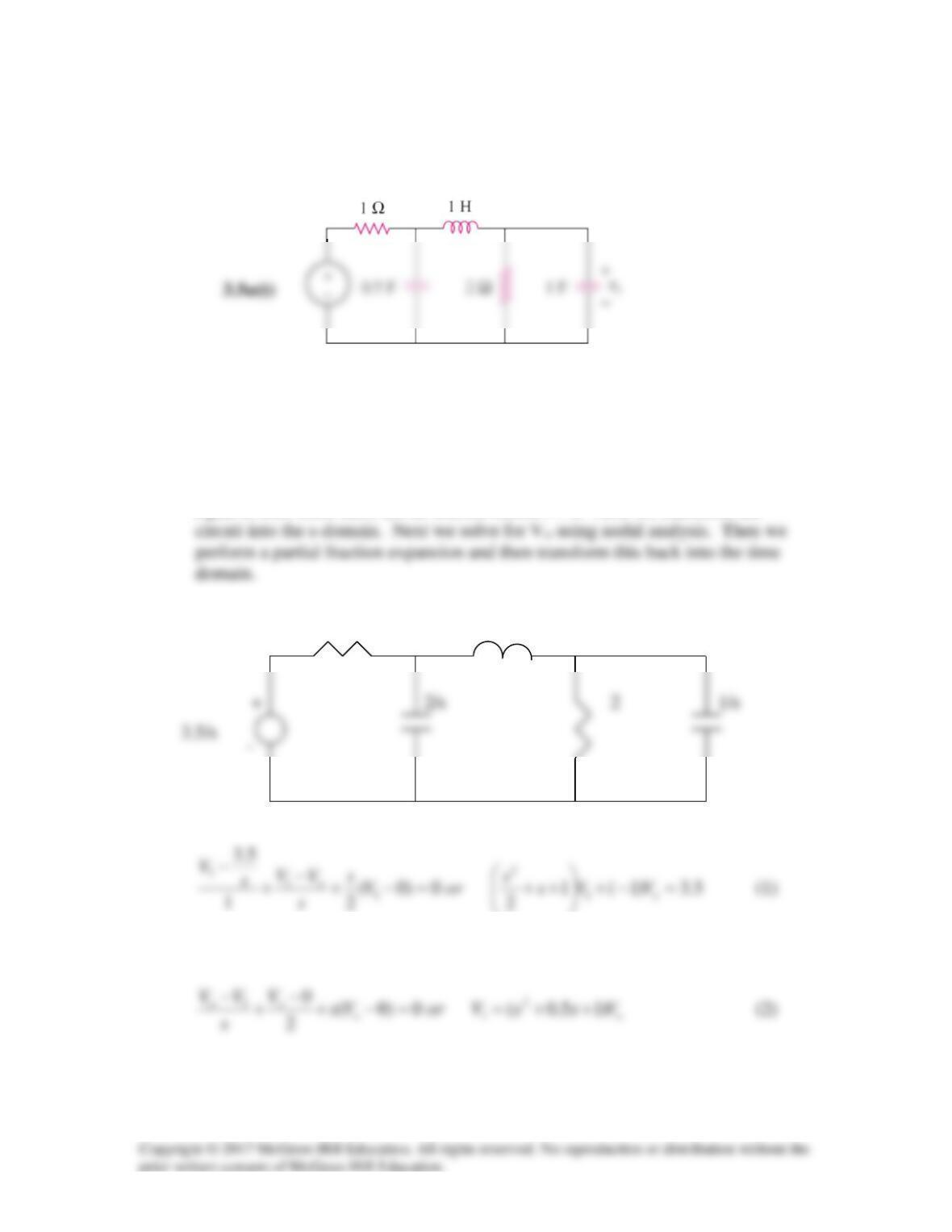
Find the voltage vo(t) in the circuit of Fig. 16.84 by means of the Laplace transform.
Figure 16.84
For Prob. 16.61.
Solution
Step 1. We first need to determine the initial conditions which in this case are
equal to zero since there are no sources before t = 0. Next we transform the
1 s
V1 Vo
At node 1,
At node 2,
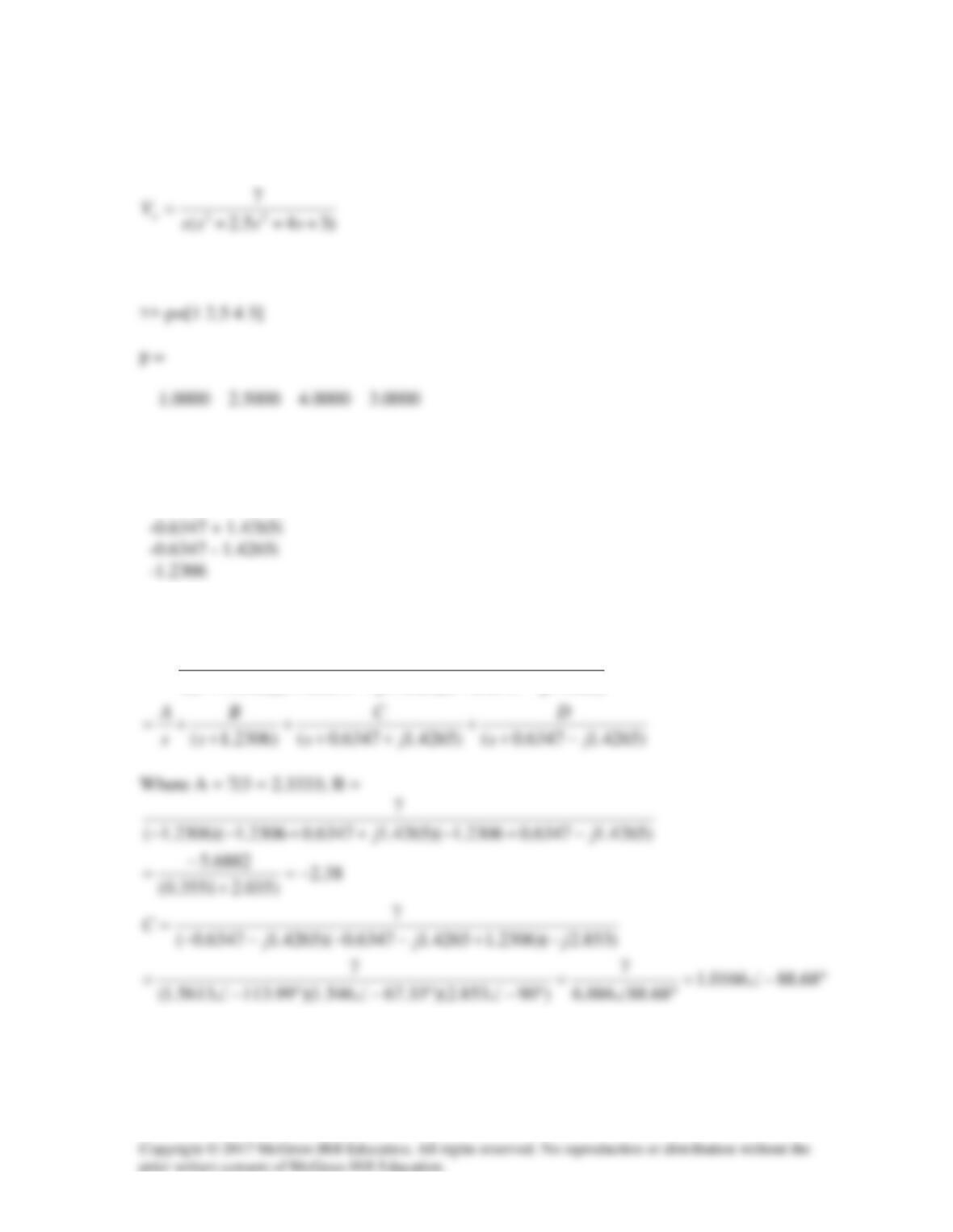
Step 2. Substituting (2) into (1) gives
ooo VssssVVssss )22345.2(5.0)15.0)(22(5.0[5.3 23422 −++++=−++++=
Use MATLAB to find the roots.
>> r=roots(p)
r =
Thus,
)4265.16347.0)(4265.16347.0)(2306.1(
7
jsjsss
V
o
−++++
=