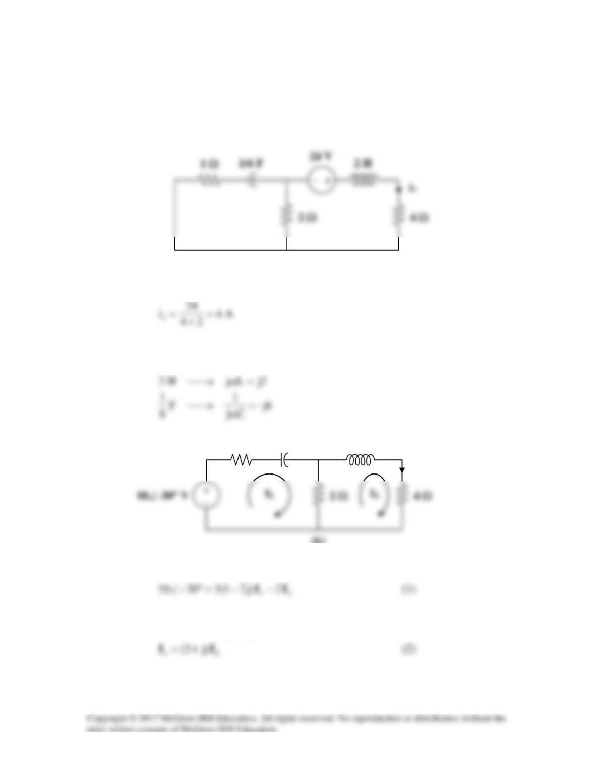
Solution 10.47
Let
321o
iiii ++=
, where
1
i
,
2
i
, and
3
i
are respectively due to the 24-V dc source, the
ac voltage source, and the ac current source. For
1
i
, consider the circuit in Fig. (a).
1 Ω
Since the capacitor is an open circuit to dc,
For
2
i
, consider the circuit in Fig. (b).
1=ω
For mesh 1,
02)6j3(30–10–
21
=−−+°∠ II
For mesh 2,
21
)2j6(2–0 II ++=
(b)
I2
j2 Ω
I1
I2
–j6 Ω
1 Ω
(a)
Substituting (2) into (1)
15j1330–10 I−=°∠
For 3
i
, consider the circuit in Fig. (c).
3=ω
Using current division,
)2j1(2
)02(
2j3
)2j1(2
−
°∠⋅
−
−
(c)
I3
j6 Ω
–j2 Ω
1 Ω
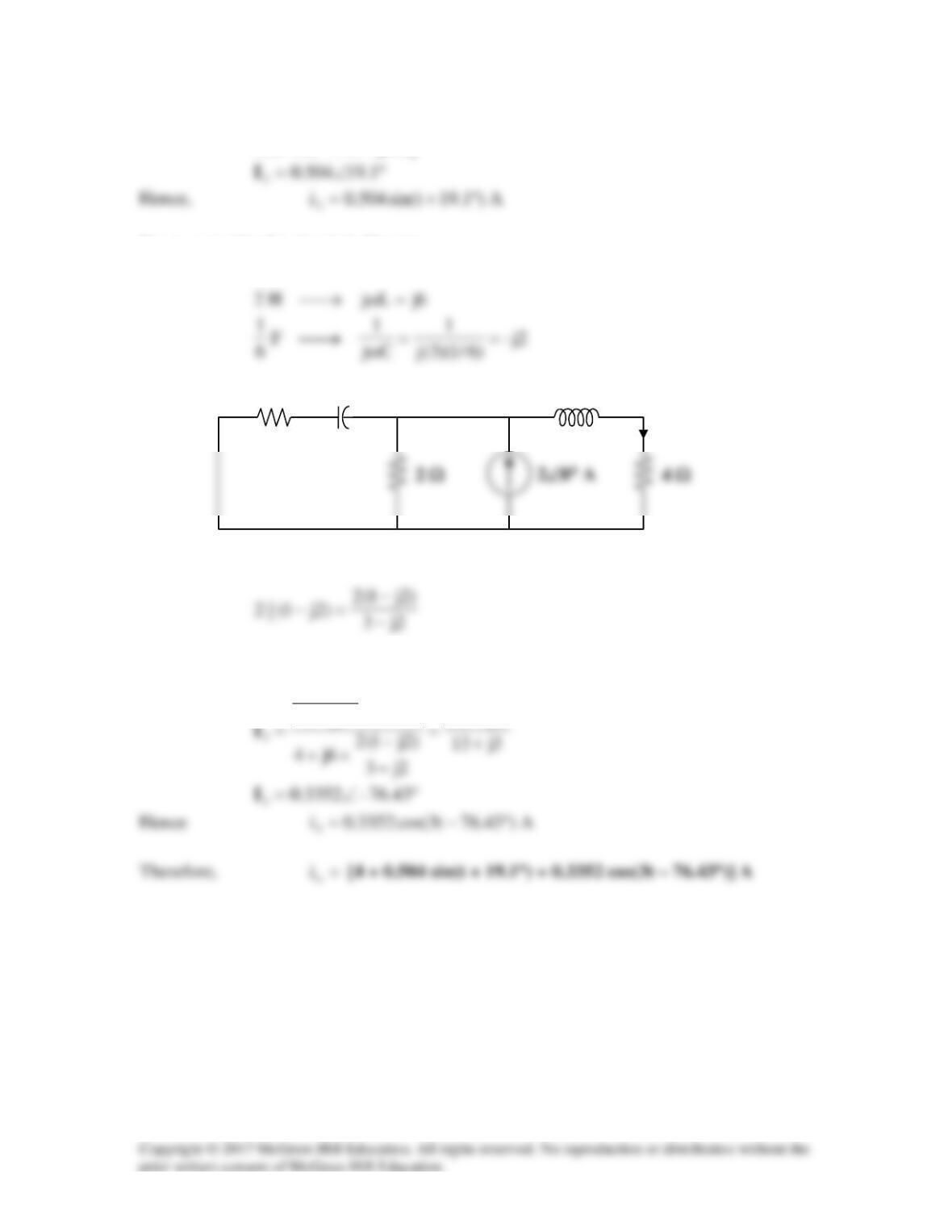
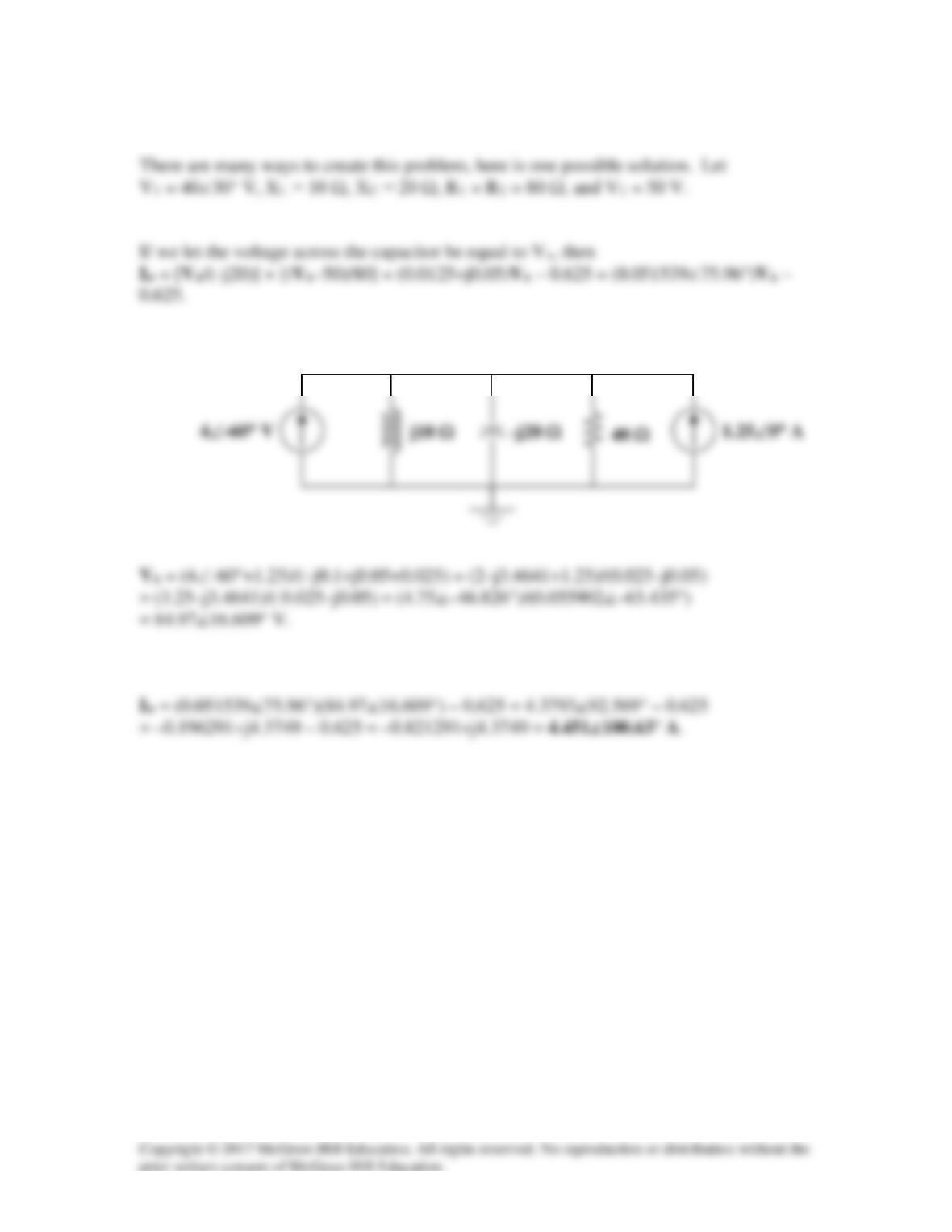
Solution 10.48
Find io in the circuit in Fig. 10.93 using superposition.
Figure 10.93
For Prob. 10.48.
Solution
Let io = i1 + i2 + i3, where I1 is due to the ac voltage source, I2 is due to the dc voltage
source, and I3 is due to the ac current source. For I1, consider the circuit in Fig. (a).
2000=ω
(a)
I
-j25 Ω
I1
Using current division,
°∠
18030
1
80
–I–
For I2, consider the circuit in Fig. (b).
60 Ω
For I3, consider the circuit in Fig. (c).
4000=ω
`
I2
80 Ω
100 Ω
(c)
-j12.5 Ω
For mesh 1,
For mesh 2,
For mesh 3,
Simplifying and substituting (1) into this equation yields
Substituting (3) into (2) yields
375.16236)25.4416( jj +=+
c
I
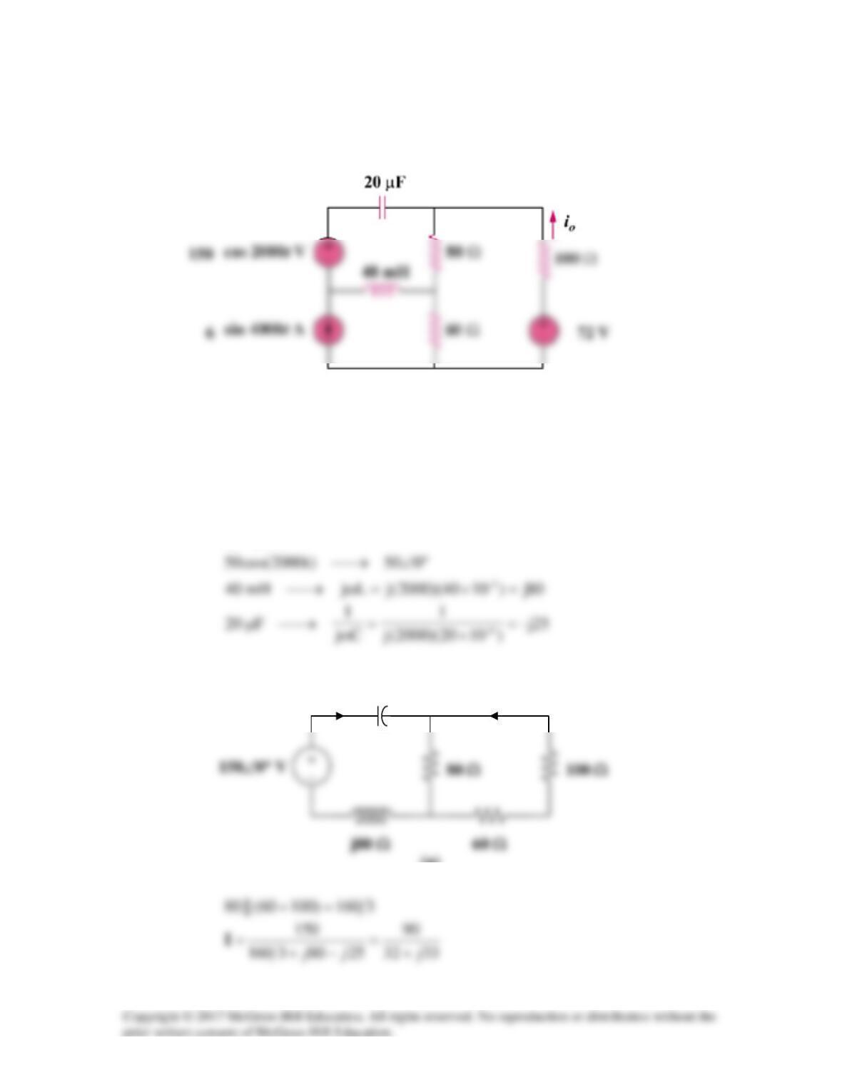
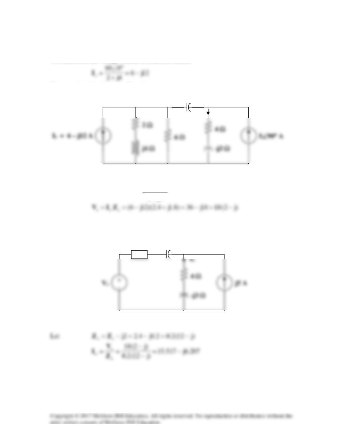
Solution 10.49
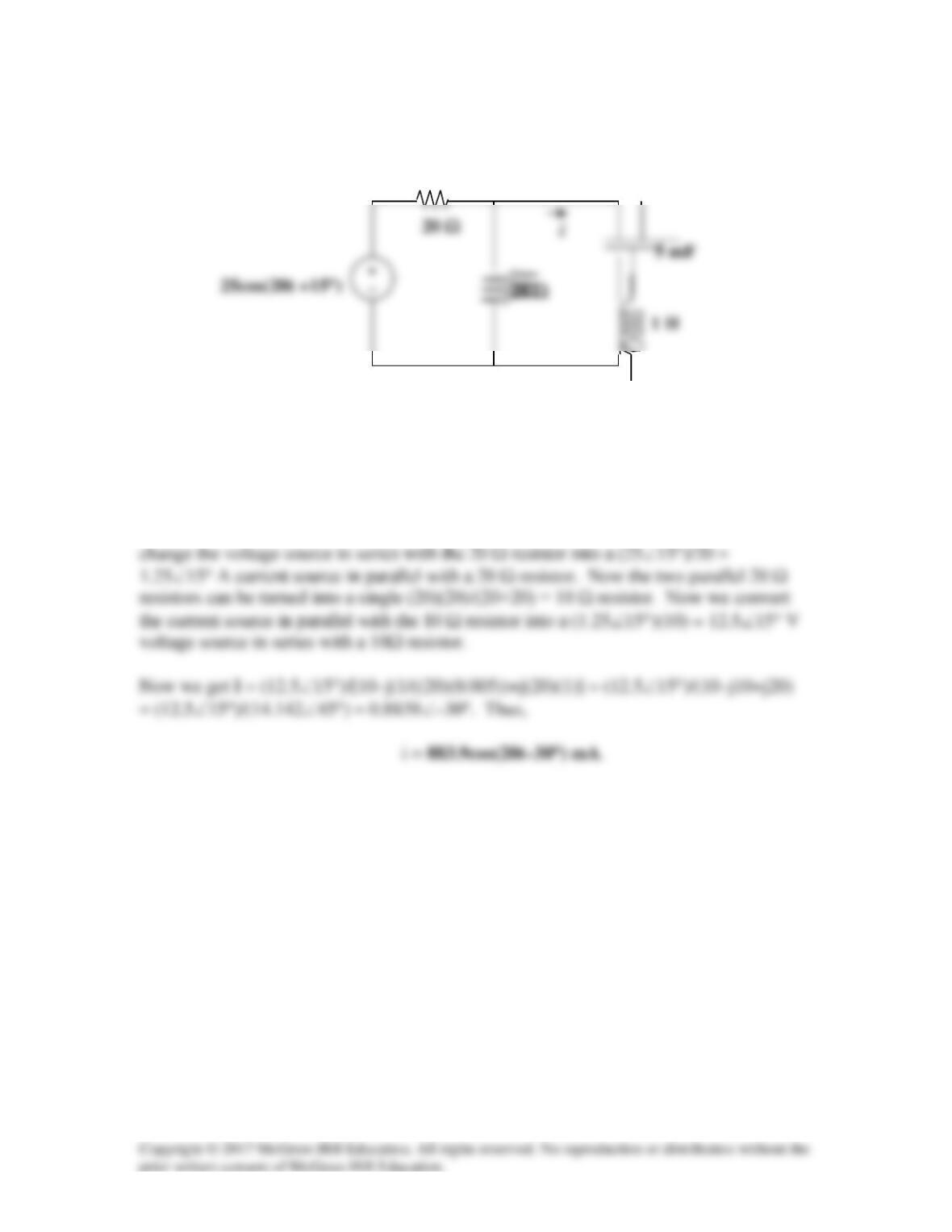
Using source transformation, find i in the circuit of Fig. 10.94.
Figure 10.94
For Prob. 10.49.
Solution
First we convert the circuit into the frequency domain and use source transformation to
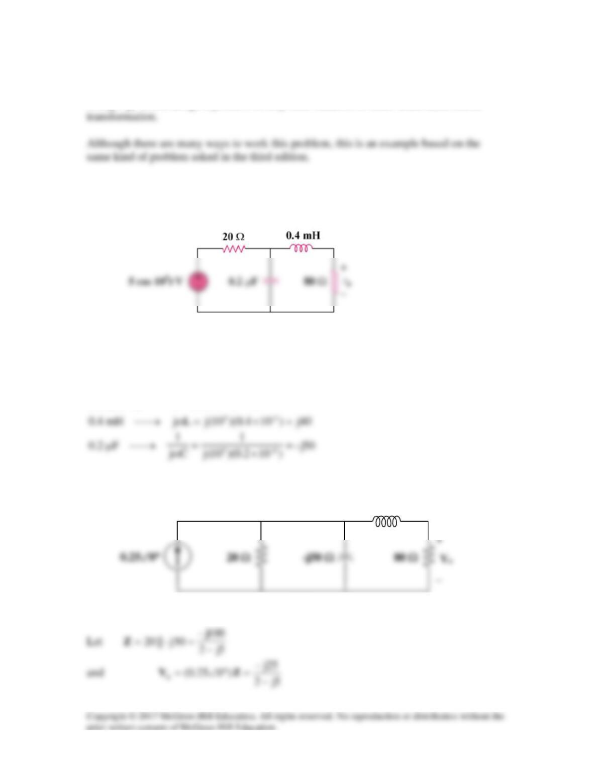
Solution 10.50
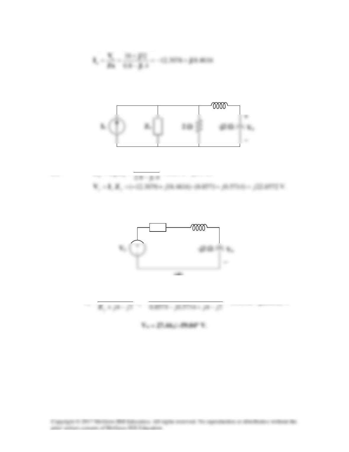
Using Fig. 10.95, design a problem to help other students to better understand source
Problem
Use source transformation to find vo in the circuit in Fig. 10.95.
Figure 10.95
Solution
55
10,05)t10cos(5=ω°∠→
After transforming the voltage source, we get the circuit in Fig. (a).
(a)
j40 Ω
With these, the current source is transformed to obtain the circuit in Fig.(b).
By voltage division,
(b)
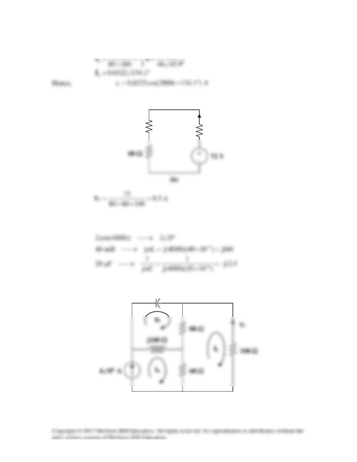
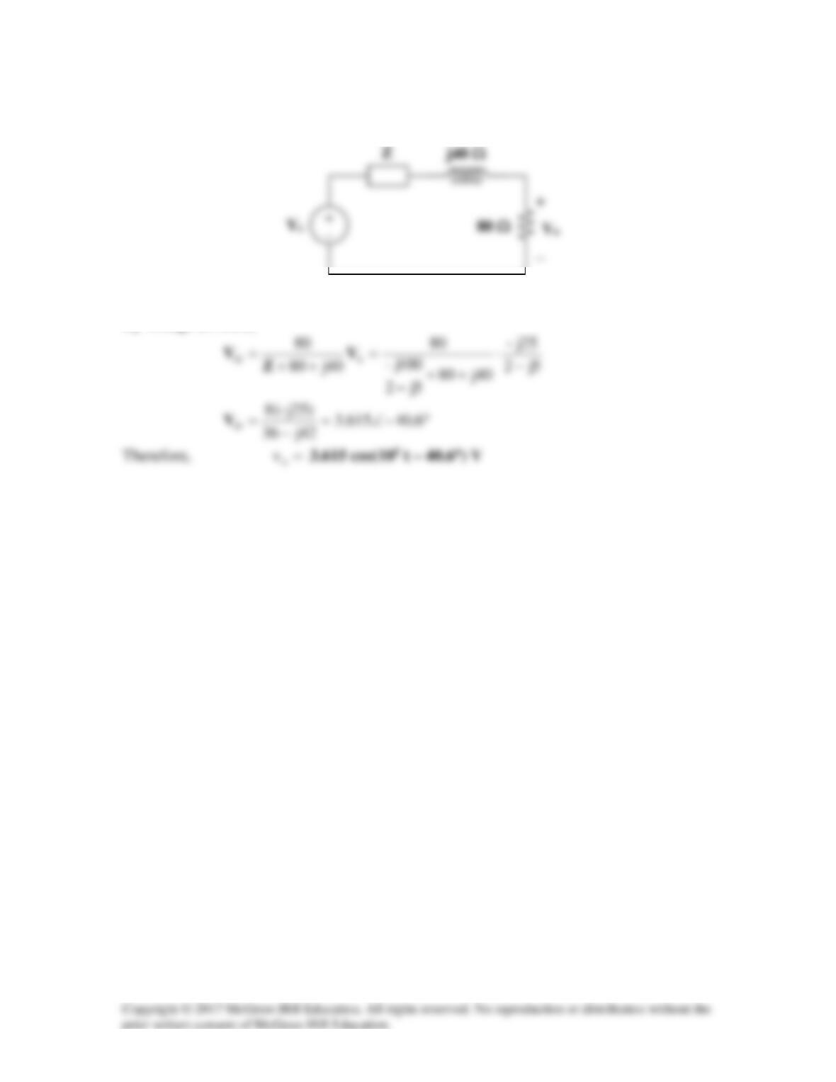
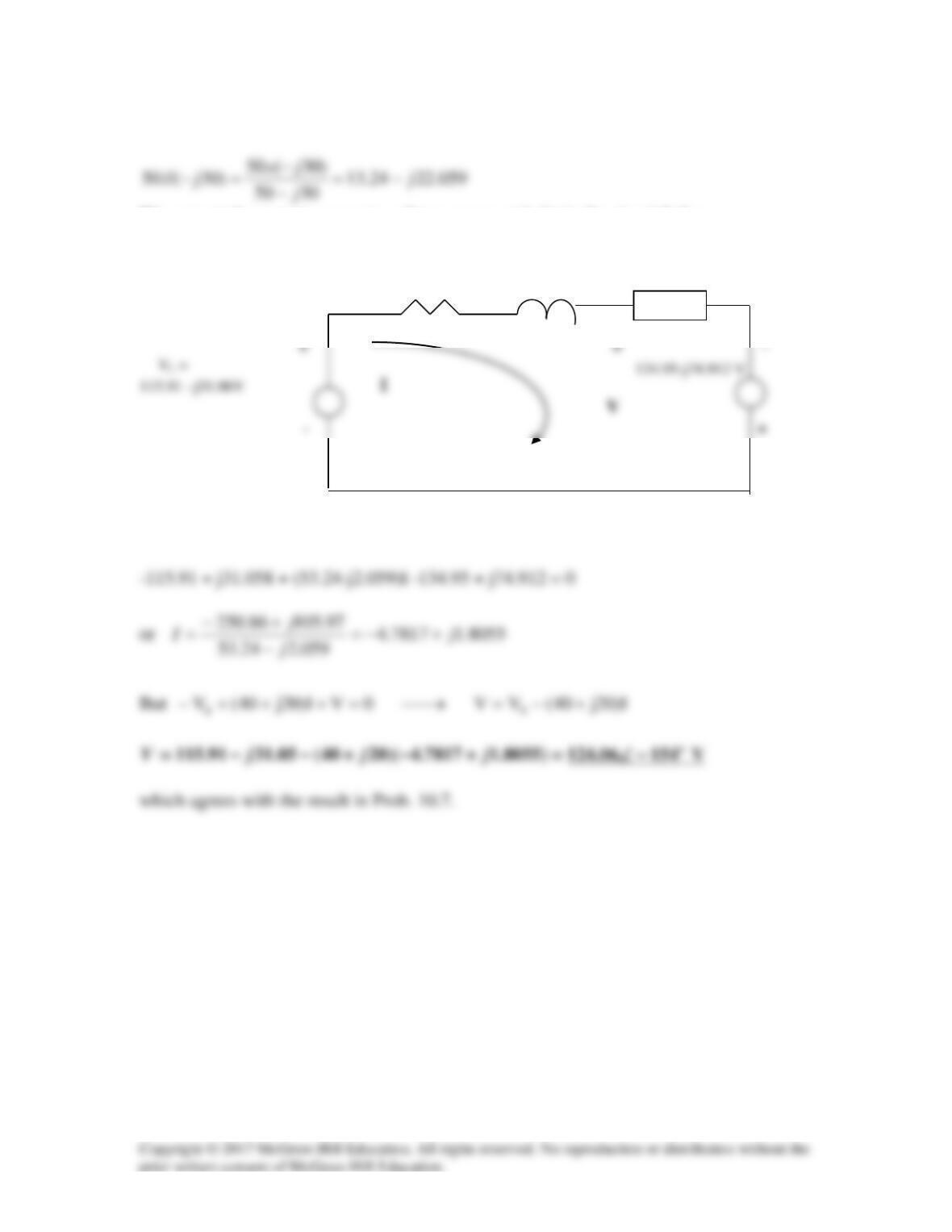
Solution 10.51
The following circuit is obtained by transforming the voltage sources.
Therefore,
Vx
Solution 10.52
We transform the voltage source to a current source.
The new circuit is shown in Fig. (a).
Let
8.1j4.2
4j8
)4j2(6
)4j2(||6
s+=
+
+
=+=Z
With these, we transform the current source on the left hand side of the circuit to a
voltage source. We obtain the circuit in Fig. (b).
(a)
Ix
–j2 Ω
(b)
Ix
–j2 Ω
Zs
With these, we transform the voltage source in Fig. (b) to a current source. We obtain the
circuit in Fig. (c).
Using current division,
2.0j4.2
o
−
Z
(c)
Ix
Solution 10.53
Use the concept of source transformation to find Vo in the circuit of Fig. 10.97.
Figure 10.97
For Prob. 10.53.
Solution
We transform the voltage source to a current source to obtain the circuit in Fig. (a).
8j
With these, the current source is transformed so that the circuit becomes that shown in
Fig. (b).
j4 Ω
–j3 Ω
(b)
Zs
j4 Ω
–j3 Ω
(a)
Let
4.1j8.03j
sx −=−= ZZ
With these, we transform the voltage source in Fig. (b) to obtain the circuit in Fig. (c).
Let
5714.0j8571.0
8.2j6.1
||2 xy −=
−
== ZZ
With these, we transform the current source to obtain the circuit in Fig. (d).
Using current division,
=
=
=245714.08571.0
)8572.22(2–
2–
jj
j
V
(14.116 – j23.532) V.
j4 Ω
(d)
+
Zy
j4 Ω
(c)
+
Solution 10.54
We convert the current source to voltage source and obtain the circuit below.
13.24 – j22.059
Ω
40
Ω
j20
Ω
–
Applying KVL gives
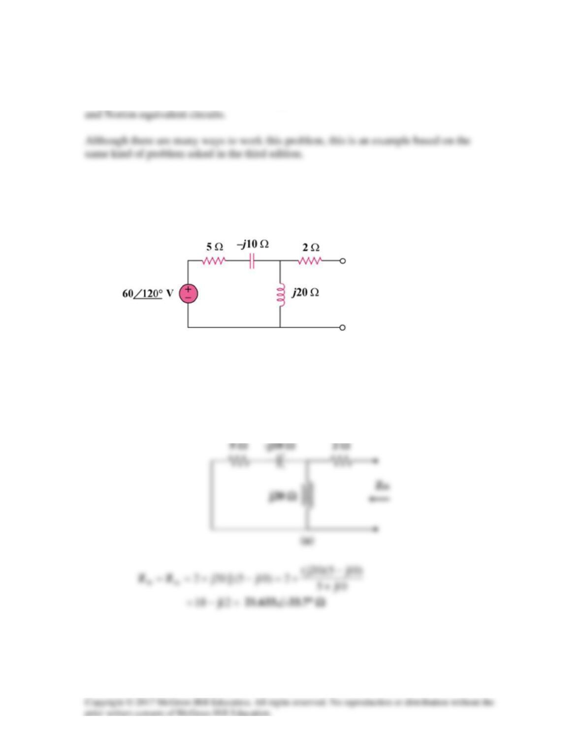
Solution 10.55
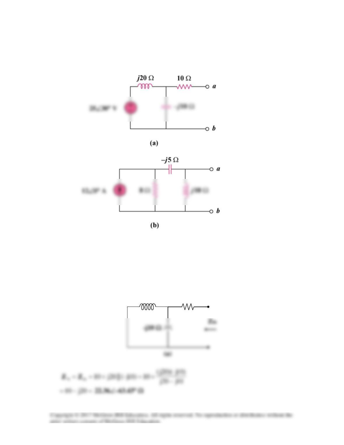
Find the Thevenin and Norton equivalent circuits at terminals a–b for each of the circuits
in Fig. 10.98.
Figure 10.98
For Prob. 10.55.
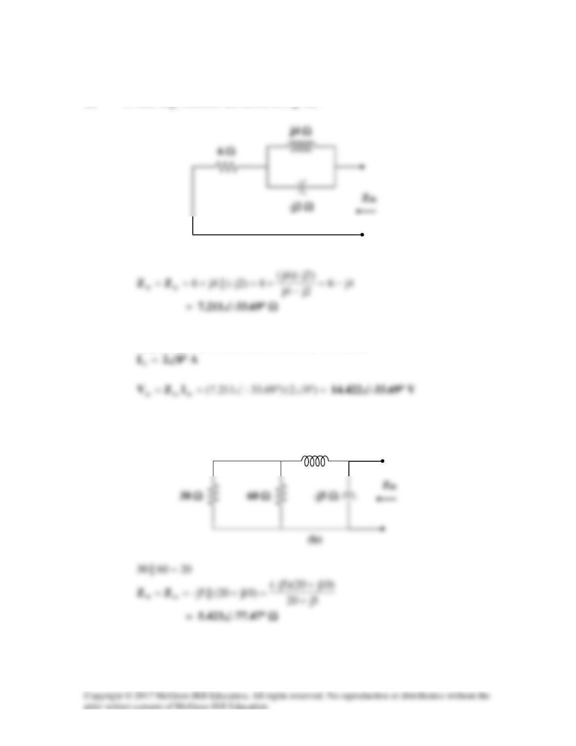
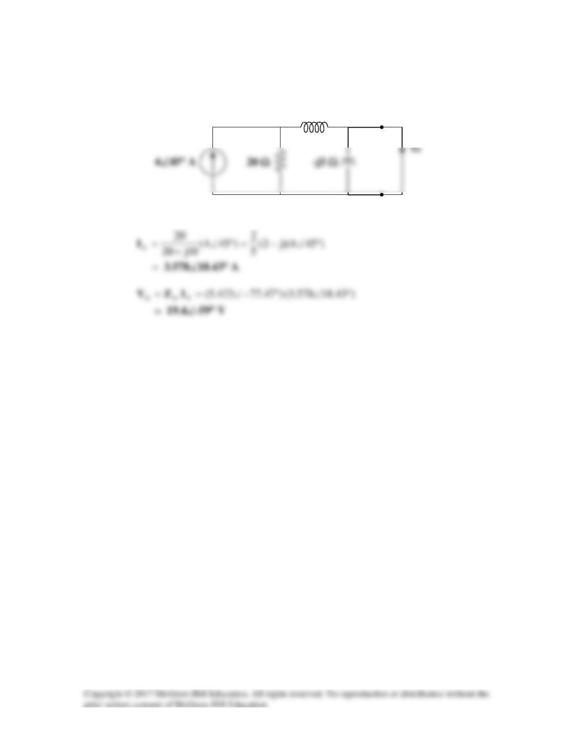
Solution
(a) To find
th
Z
, consider the circuit in Fig. (a).
j20 Ω
10 Ω
To find
th
V
, consider the circuit in Fig. (b).
(b)
(b) To find
th
Z
, consider the circuit in Fig. (c).
To obtain th
V
, consider the circuit in Fig. (d).
j20 Ω
10 Ω
–j5 Ω
(d)
–j5 Ω
Io
By current division,
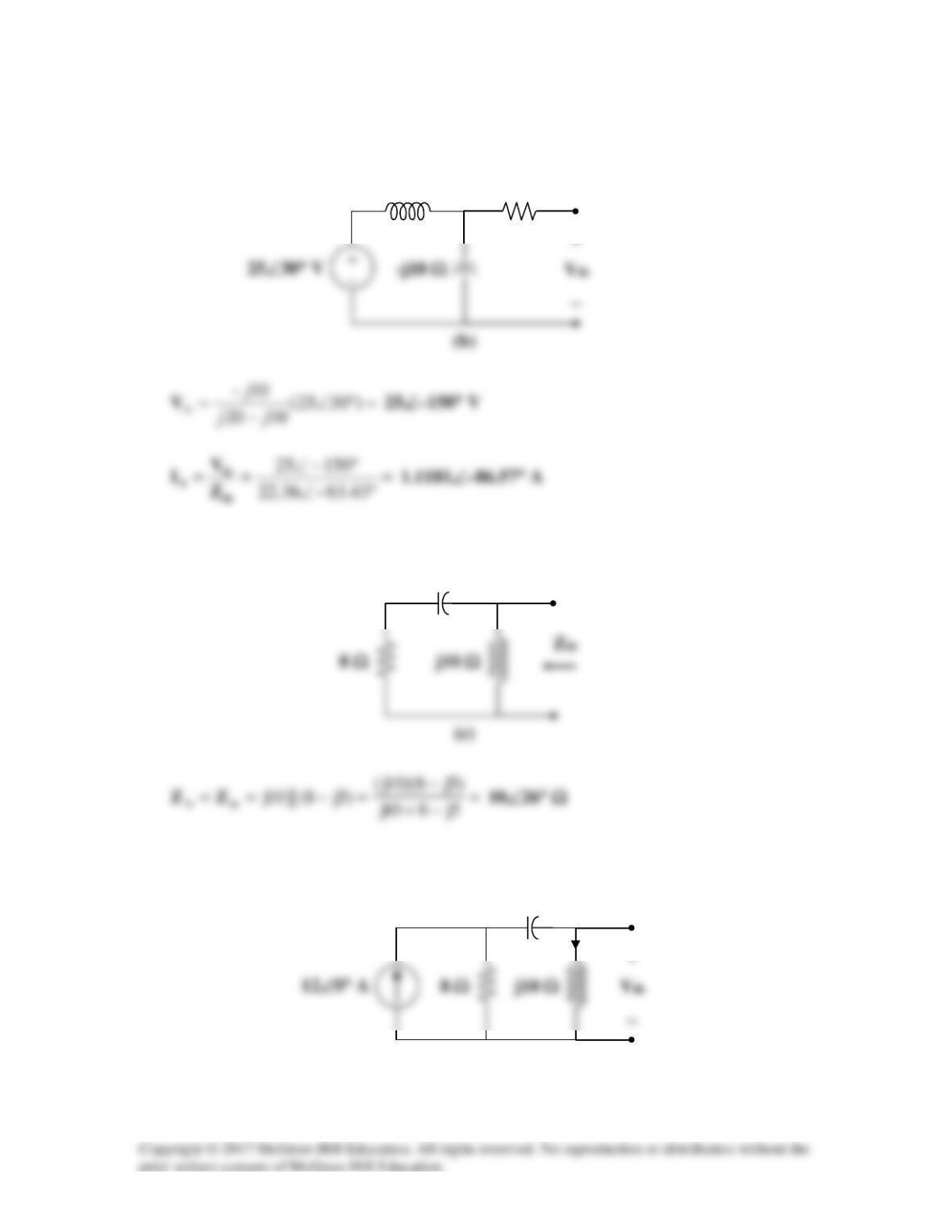
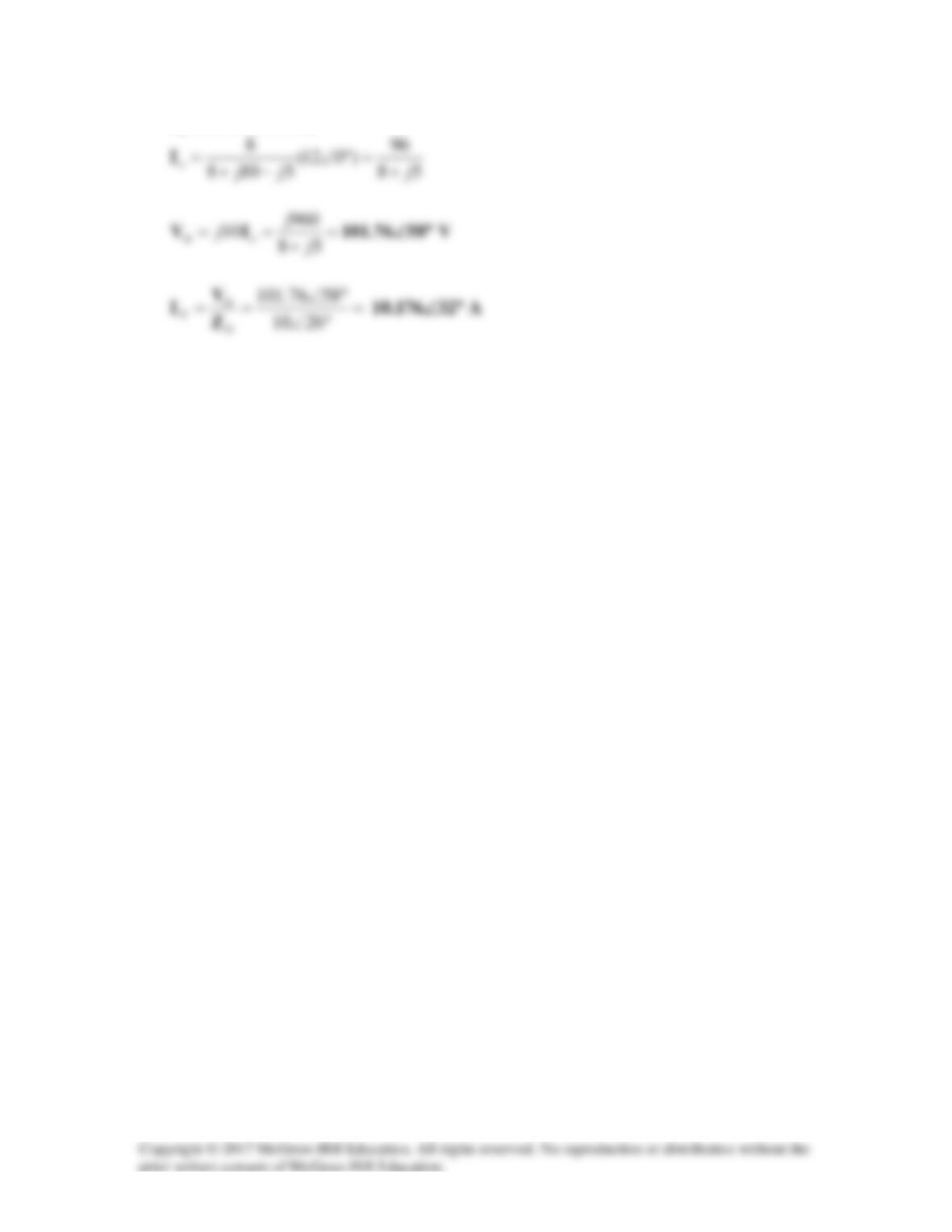
Solution 10.56
(a) To find
th
Z
, consider the circuit in Fig. (a).
By placing short circuit at terminals a–b, we obtain,
(b) To find
th
Z
, consider the circuit in Fig. (b).
(b)
(a)
j10 Ω
To find
th
V
and
N
I
, we transform the voltage source and combine the 30 Ω and 60 Ω
resistors. The result is shown in Fig. (c).
(c)
j10 Ω
a
(a)
b
Solution 10.57
Using Fig. 10.100, design a problem to help other students to better understand Thevenin
Problem
Find the Thevenin and Norton equivalent circuits for the circuit shown in
Fig. 10.100.
Figure 10.100
Solution
To find
th
Z
, consider the circuit in Fig. (a).