Solution 14.74
Ω=== 300100x3RK‘R 1m1
Solution 14.75
Ω=== 20010x20RK‘R
m
1
Solution 14.76
3
‘ 500 5 10 25 M
m
R KR xx= = = Ω
Solution 14.77
L and C are needed before scaling.
H2
5
10
B
R
L
L
R
B===→=
(a)
===
′)2)(600(LKL m
kH200.1
(b)
===
′
3
10
2
K
L
L
mH2
Solution 14.78
Ω===
′k1)1)(1000(RKR m
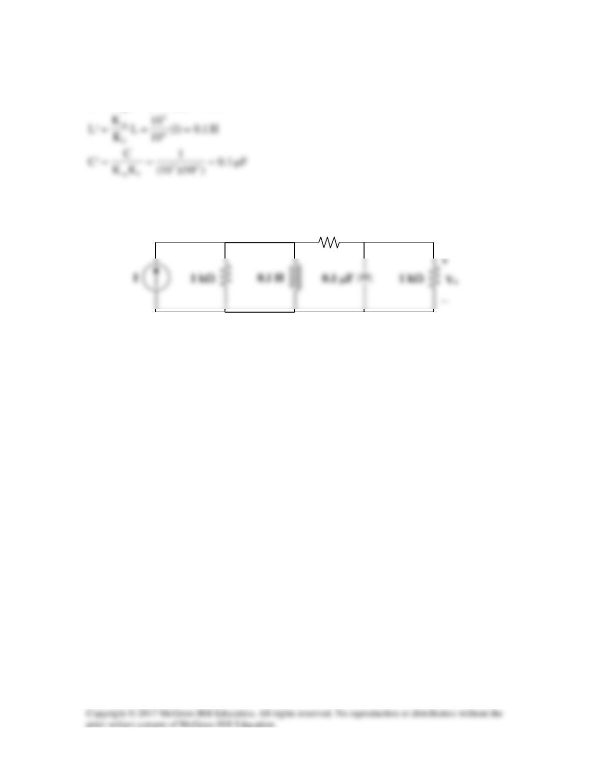
The new circuit is shown below.
1 kΩ
Solution 14.79
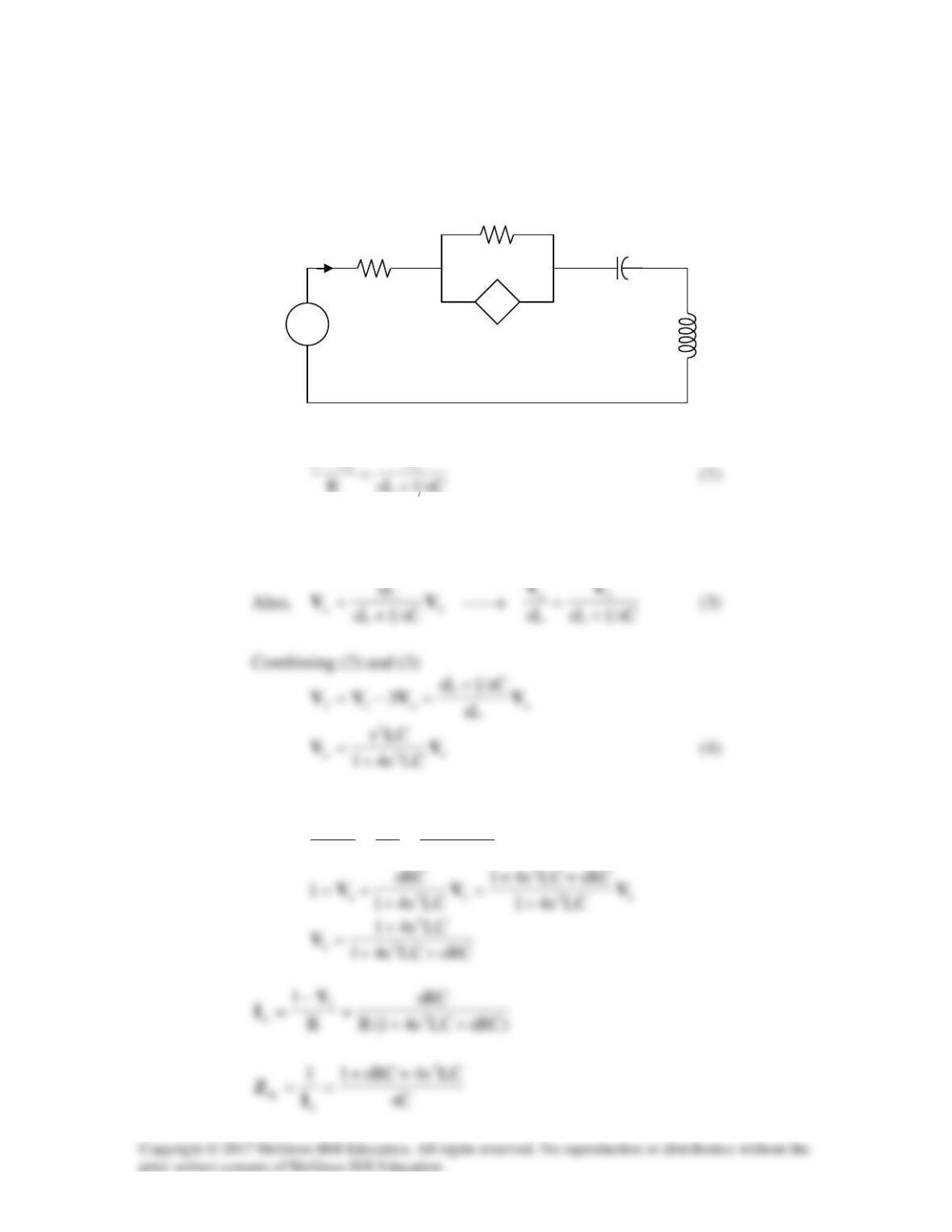
(a) Insert a 1–V source at the input terminals.
There is a supernode.
1
−VV
But
o12o21 33 VVVVVV −=→+=
(2)
Substituting (3) and (4) into (1) gives
1
2
o
1
LCs41
sC
sLR
1V
V
V
+
==
−
R
o
1/sC
R
+
−
sL
1 V
V1
V2
Io
+
Vo
−
3Vo
+ −
s
(b) After scaling,
RKR
m
→
′
From (5),
Solution 14.80
(a)
Ω===
′400)2)(200(RKR
m
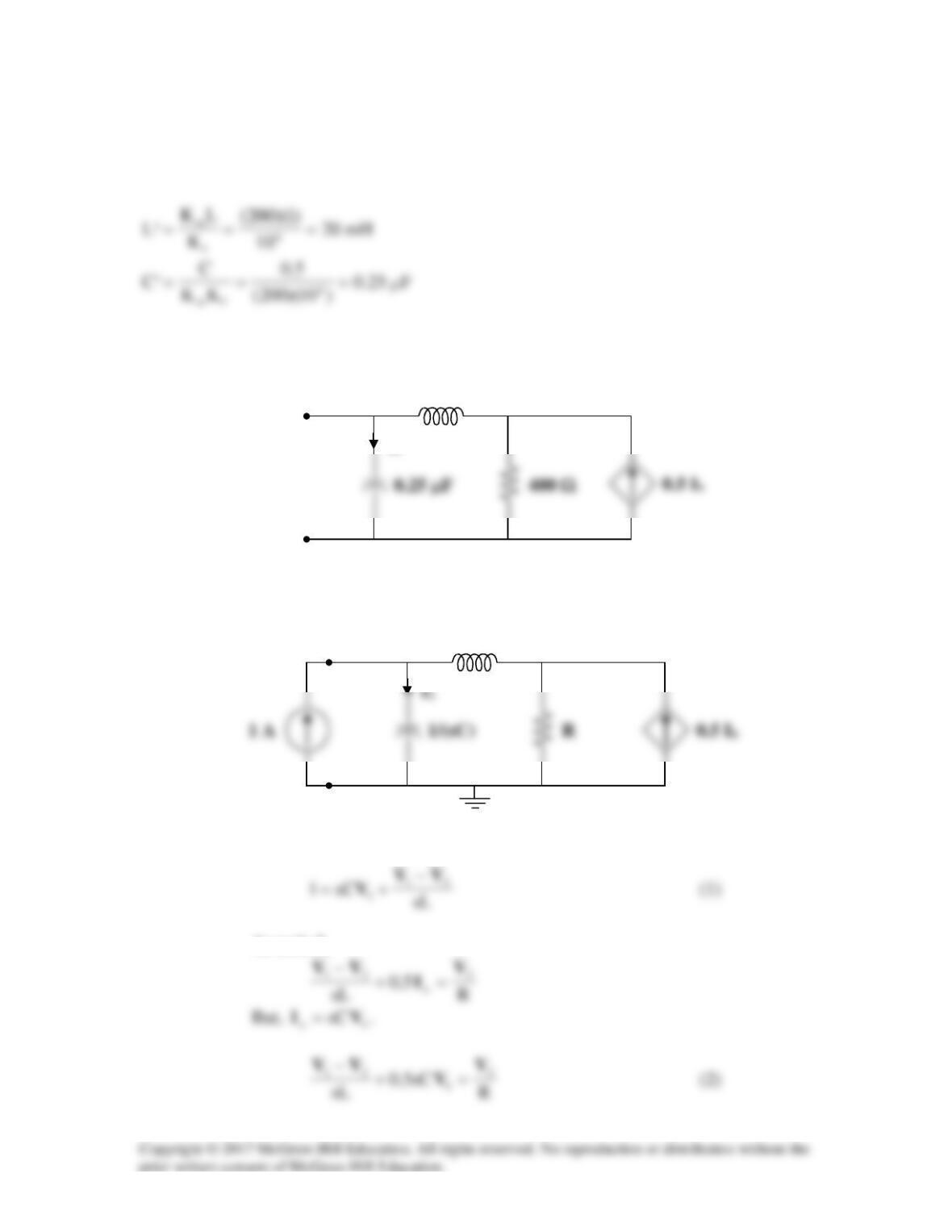
The new circuit is shown below.
(b) Insert a 1–A source at the terminals a-b.
At node 1,
At node 2,
I
x
20 mH
a
b
sL
a
b
V1
V2
Solving (1) and (2),
1sCR5.0LCs
RsL
2
1++
+
=V
Solution 14.81
(a)
RLj
Ztoleadswhich
1)LjR)(CjG(
1
1
+ω
=
+ω+ω+
We compare this with the given impedance:
Comparing (1) and (2) shows that
LR1 R/LmF, 1C1000
C
1=→==→=
Thus,
(b) By frequency-scaling, Kf =1000.
Solution 14.82
fm KK
C
C=
′
Solution 14.83
pF 1.0
10x100
10
C
KK
1
‘CF1 5
6
fm
===→µ
−
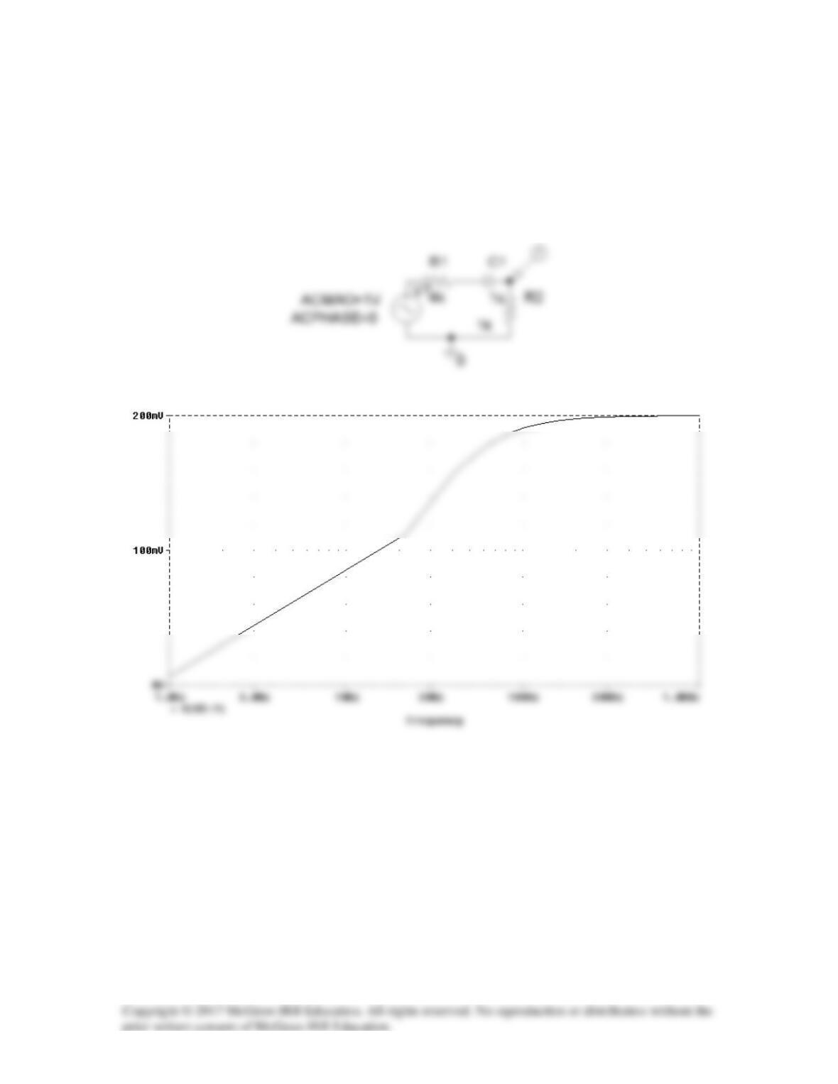
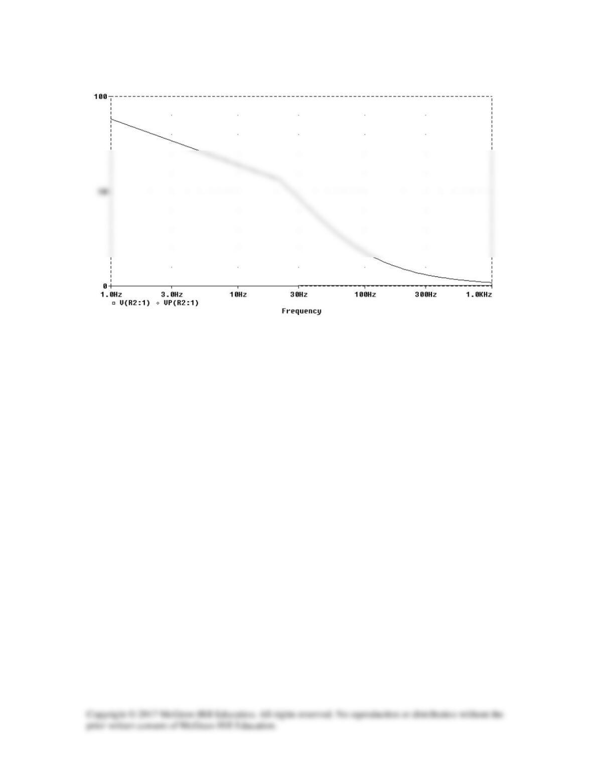
Solution 14.84
The schematic is shown below. A voltage marker is inserted to measure vo. In the AC
sweep box, we select Total Points = 50, Start Frequency = 1, and End Frequency = 1000.
After saving and simulation, we obtain the magnitude and phase plots in the probe menu
as shown below.
Solution 14.85
Solution 14.86
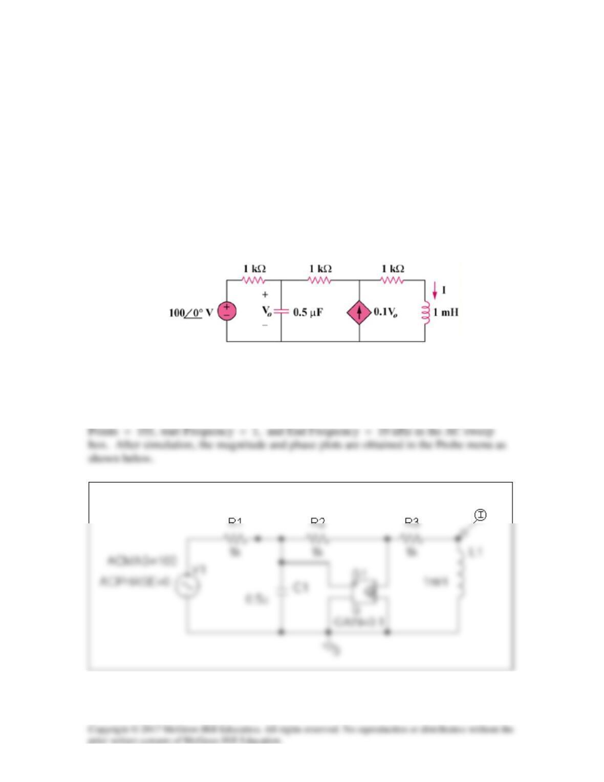
Using Fig. 14.103, design a problem to help other students to better understand how to
use PSpice to obtain the frequency response (magnitude and phase of I) in electrical
circuits.
Although there are many ways to solve this problem, this is an example based on the
same kind of problem asked in the third edition.
Problem
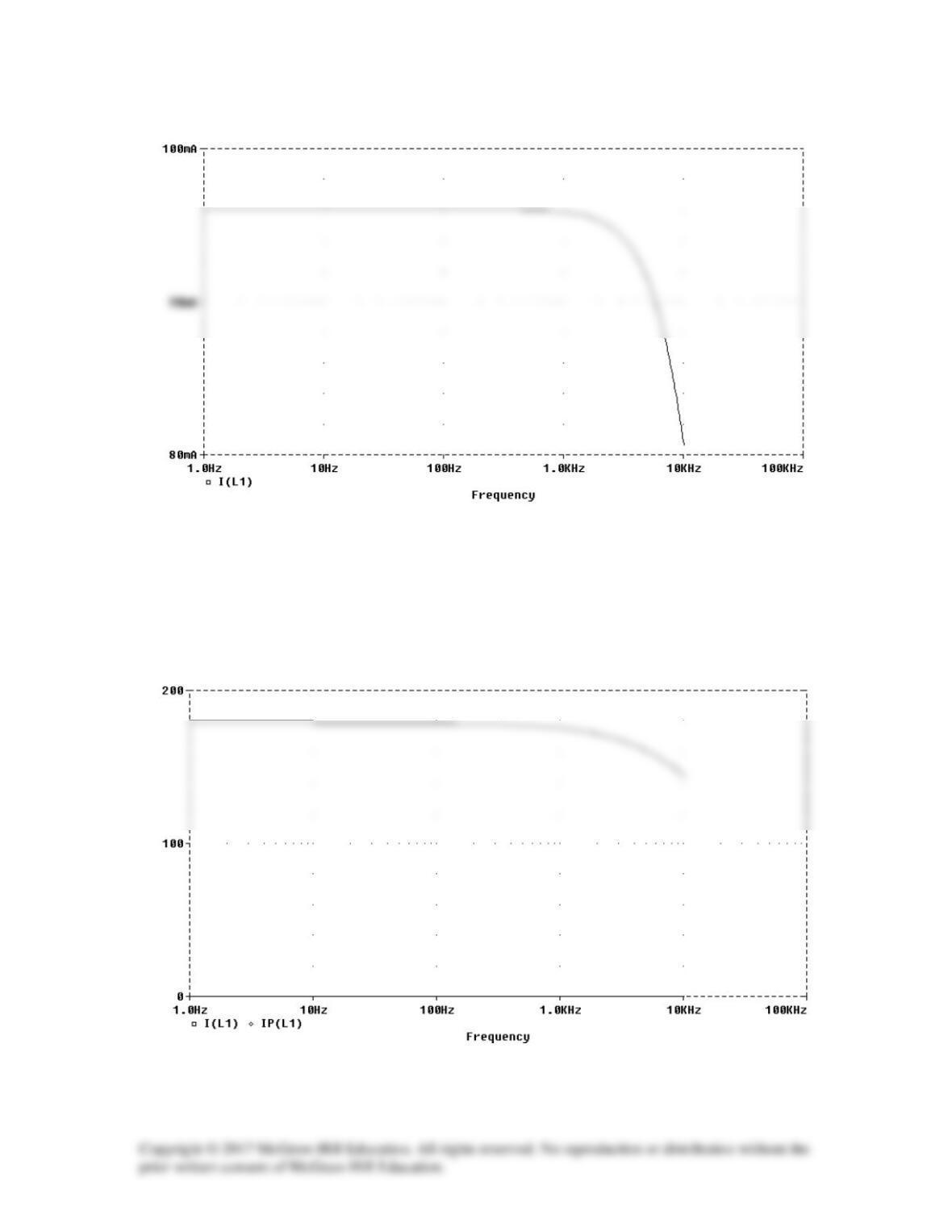
Use PSpice to provide the frequency response (magnitude and phase of i) of the circuit in
Fig. 14.103. Use linear frequency sweep from 1 to 10,000 Hz.
Figure 14.103
Solution
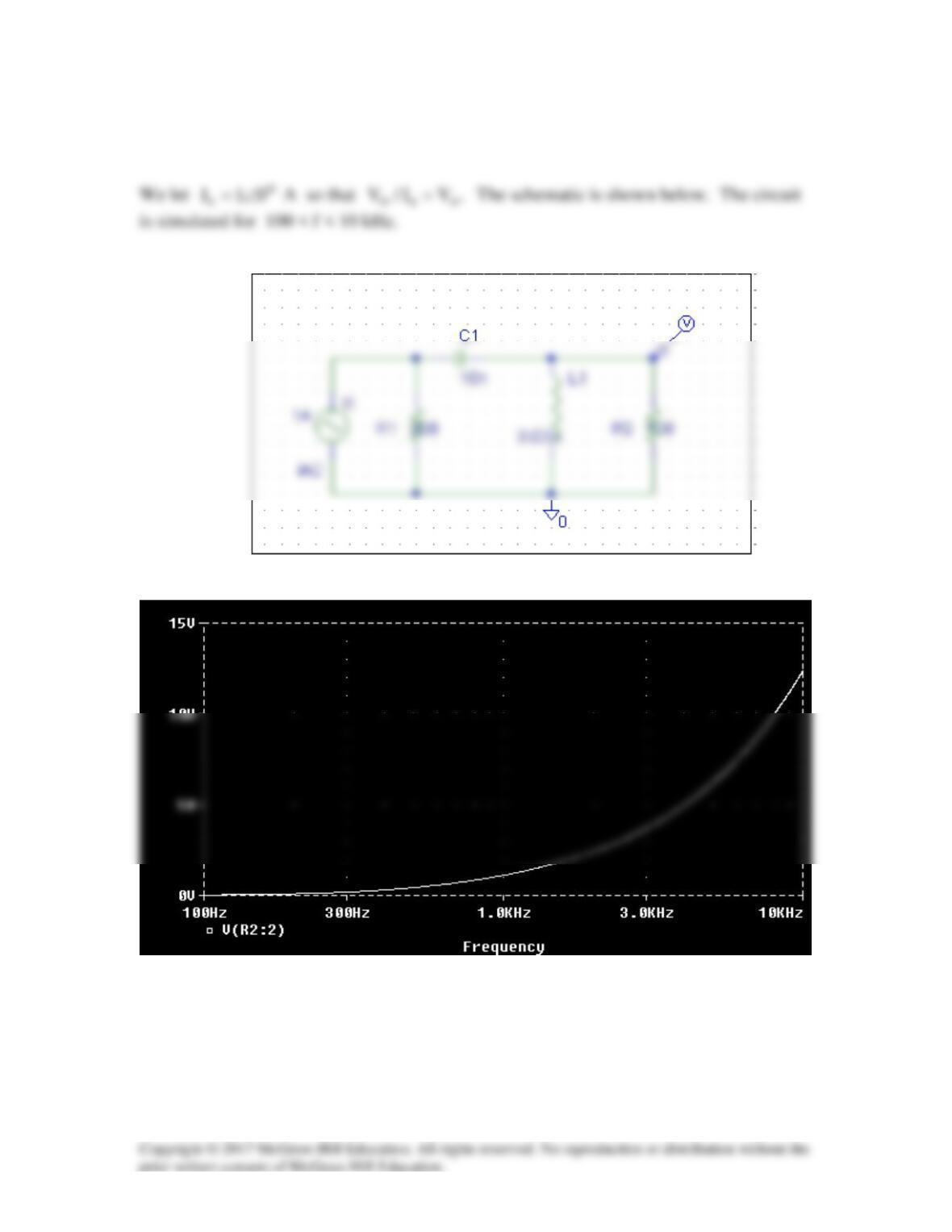
The schematic is shown below. A current marker is inserted to measure I. We set Total

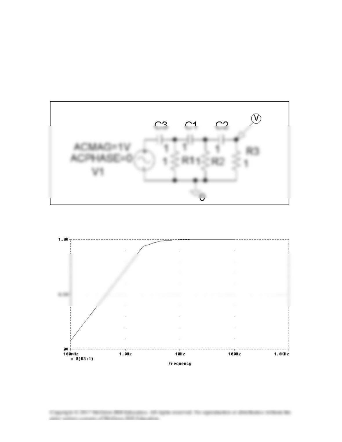
Solution 14.87
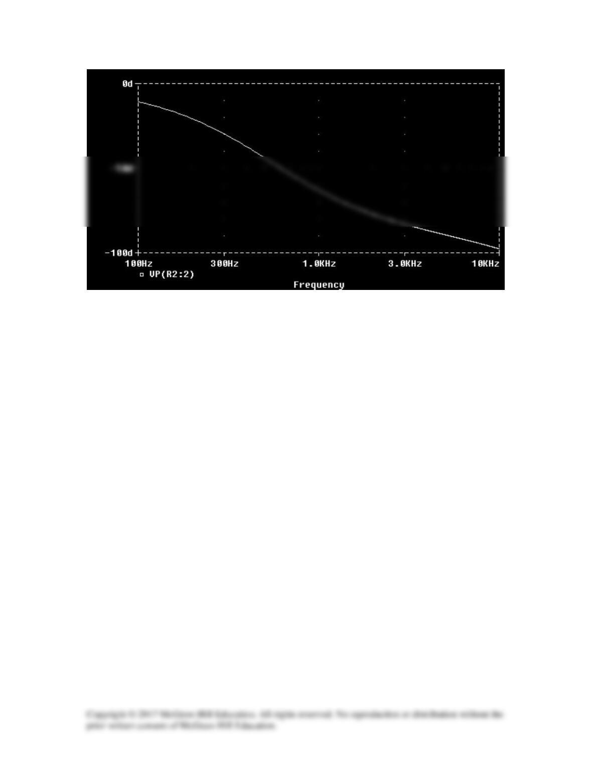
The schematic is shown below. In the AC Sweep box, we set Total Points = 50, Start
Frequency = 1, and End Frequency = 100. After simulation, we obtain the magnitude
response as shown below. It is evident from the response that the circuit represents a
high-pass filter.