Solution 10.1
We first determine the input impedance.
1 1 10 10H j L jx j
ω
→ = =
Solution 10.2
Using Fig. 10.51, design a problem to help other students better understand nodal
Problem
Solve for Vo in Fig. 10.51, using nodal analysis.
2 Ω
+
Figure 10.51 For Prob. 10.2.
Solution
Consider the circuit shown below.
2
Solution 10.3
4=ω
°∠→ 02)t4cos(2
The circuit is shown below.
Applying nodal analysis,
8j61
2
3j4
16j–
ooo
+
+=+
−
−VVV
j8 Ω
6 Ω
–j3 Ω
4 Ω
V
o
Solution 10.4
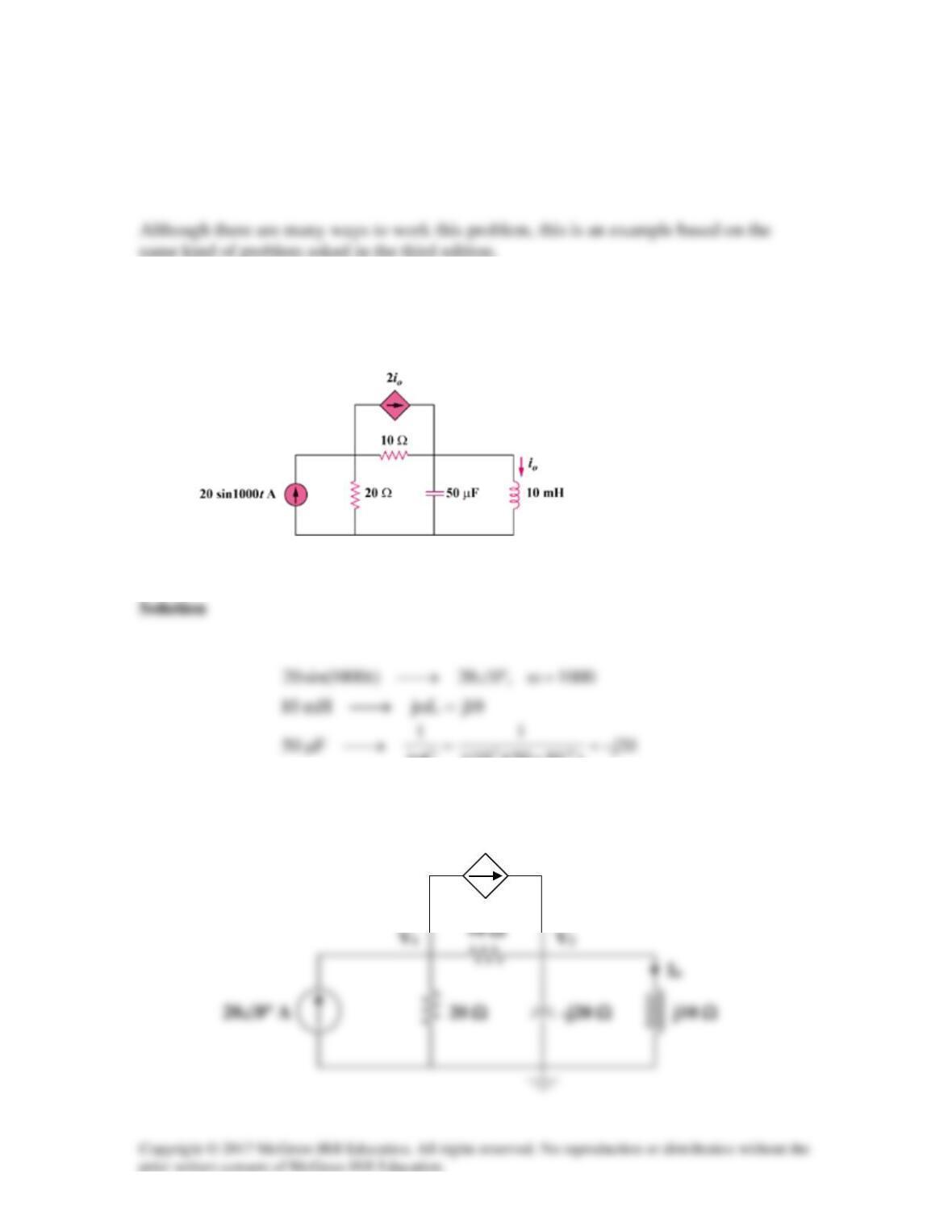
Compute vo(t) in the circuit of Fig. 10.53.
Figure 10.53
For Prob. 10.4.
Solution
Step 1. Convert the circuit into the frequency domain and solve for the node
voltage, V1, using nodal analysis. The find the current IC = V1/[1+(1/(j4x0.25)]
which then produces Vo = 1xIC. Finally, convert the capacitor voltage back into
Step 2. Now all we need to do is to solve our equations.
[(V1–24)/j] – [0.5j(V1–24] + [(V1–0)/(1–j)] = [–j–j0.5+0.5+j0.5]V1 +j24+j12 = 0
or
24cos(4t+45°) V
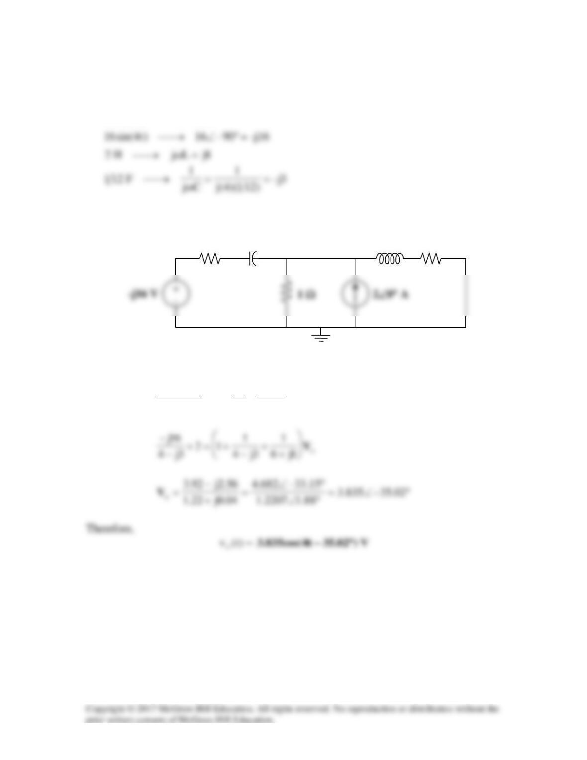
Solution 10.5
3
0.25 0.25 4 10 1000H jL j xx j
ω
→ = =
Consider the circuit as shown below.
Io 2000 Vo -j125
At node Vo,
I10V
0V
25V
oooo
−
−
−
=+−+
25V08.0j2jV)14j1(
oo
Now to solve for io,
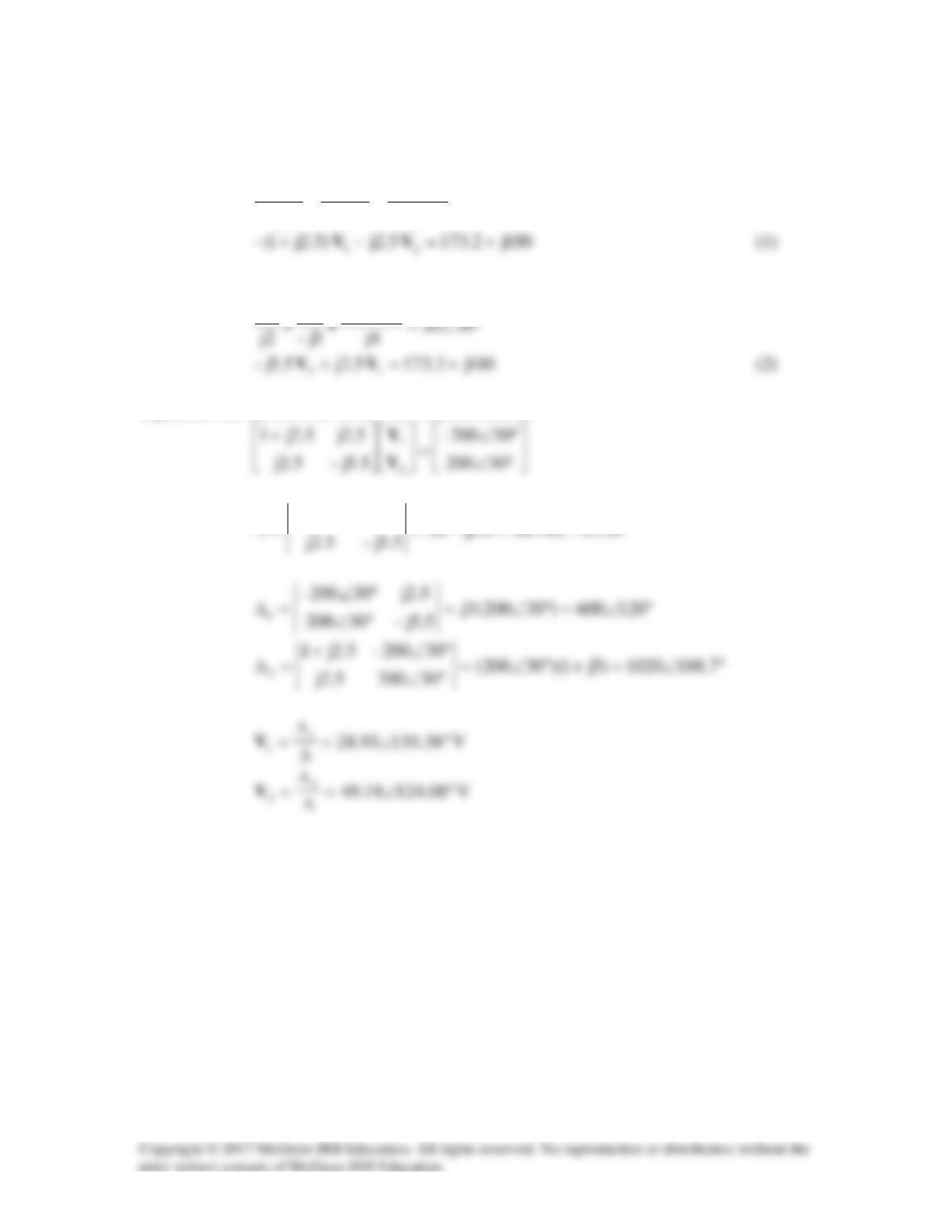
Problem 10.6
Determine Vx shown in Fig. 10.55
Figure 10.55
For Prob. 10.6.
Solution
Let Vo be the voltage across the dependent current source. Using nodal analysis we get:
+ −
Vx
20 Ω
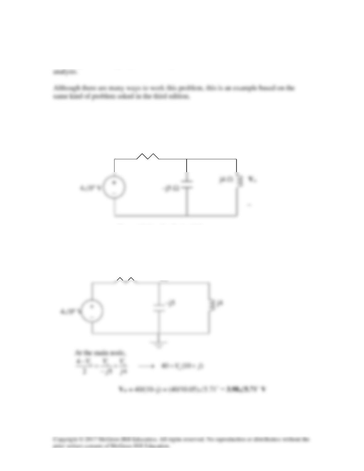
Solution 10.7
At the main node,
Solution 10.8
,200=ω
20j1.0x200jLjmH100 ==ω→
The frequency-domain version of the circuit is shown below.
0.1 Vo
At node 1,
VV
V
V
o−
At node 2,
From (1) and (2),
Using MATLAB,
leads to
09.1613.110,23.12763.70
21
jVjV +−=−−=
Solution 10.9
33
10,010)t10cos(10 =ω°∠→
Consider the circuit shown below.
At node 1,
10
2111
VVVV −
−
At node 2,
2121
−VVVV
1
V
Substituting (2) into (1)
)8.0j6.0)(j2(
++
j10 Ω
-j20 Ω
20 Ω
V1
V2
−
I
o
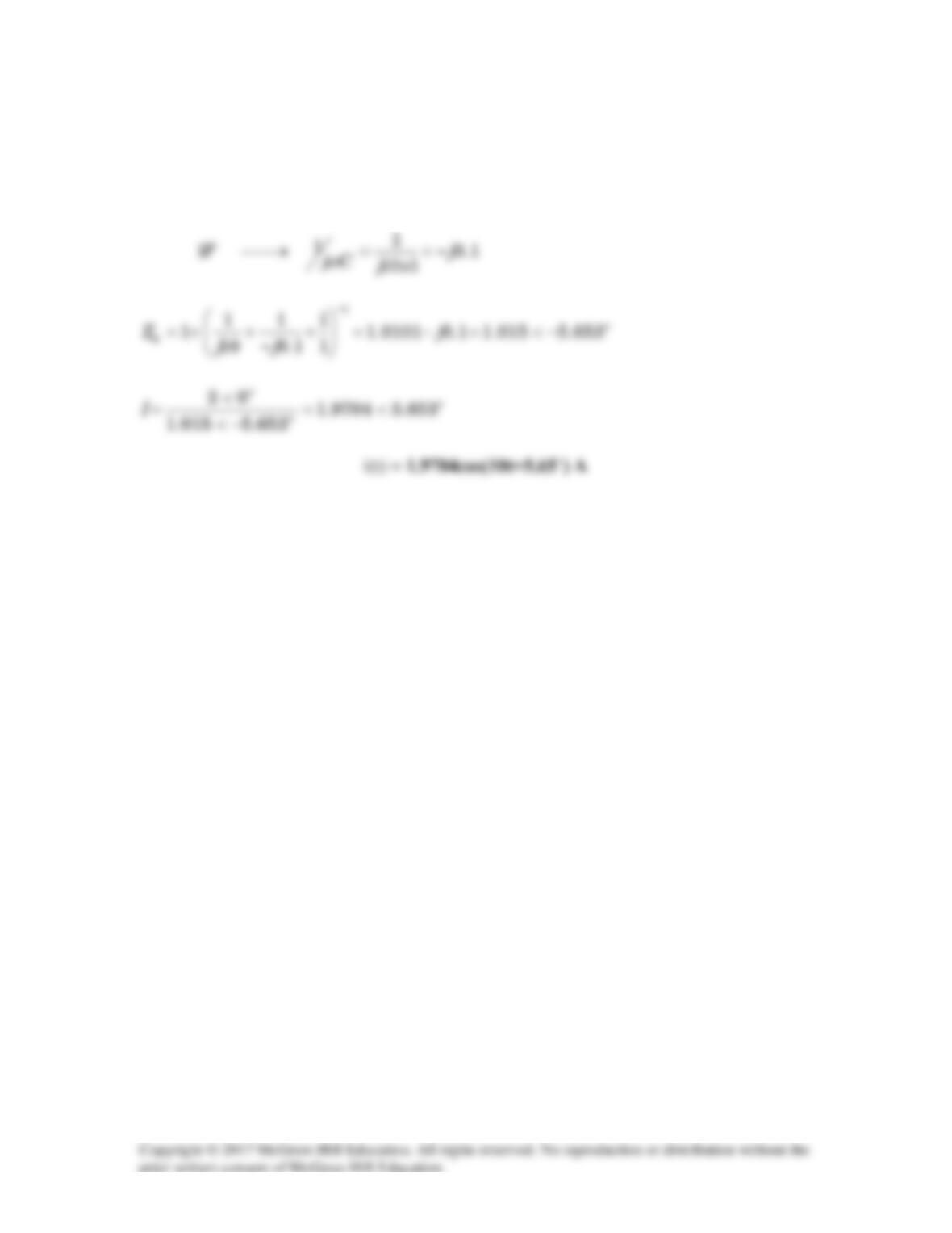
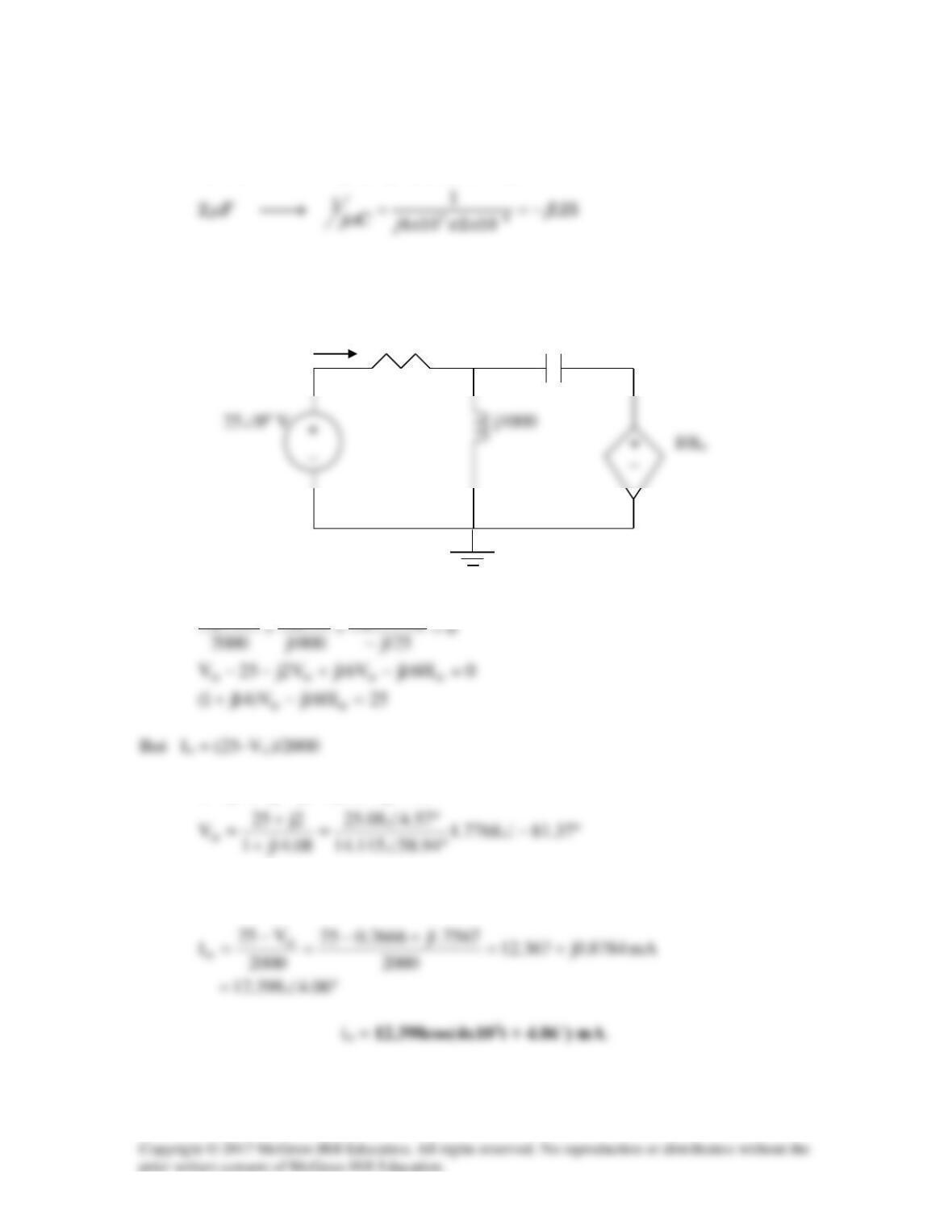
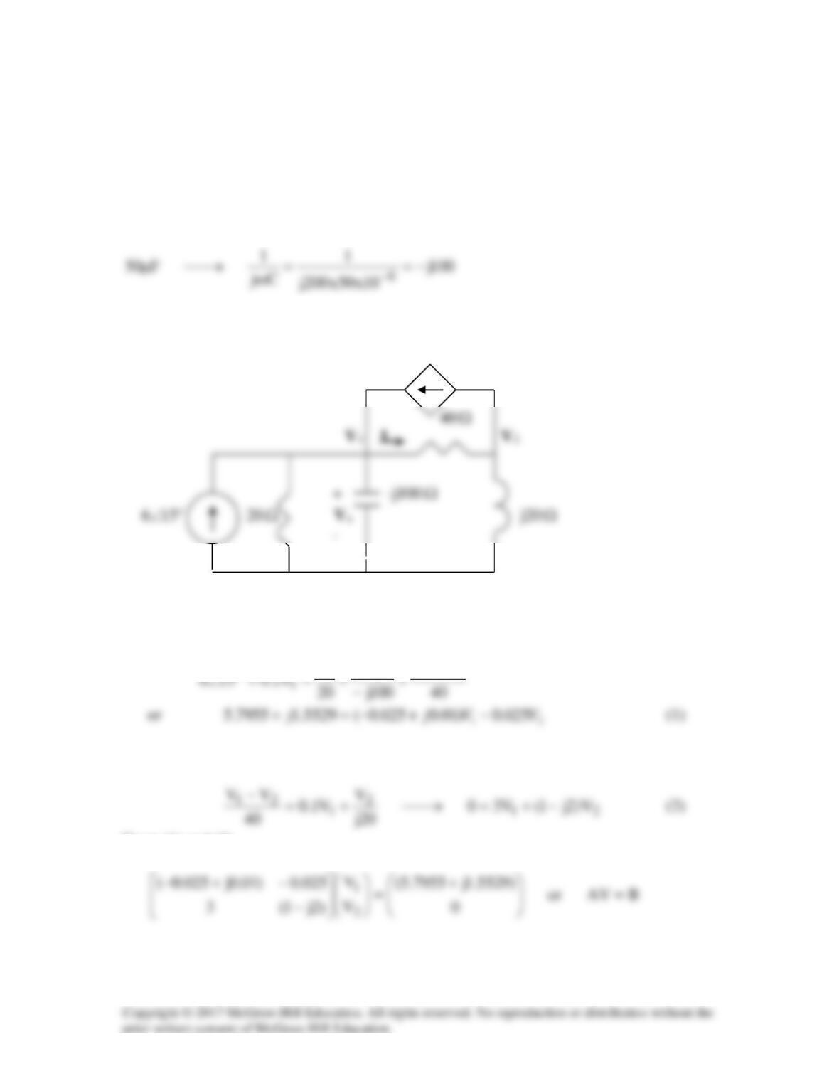
Solution 10.10
Consider the frequency-domain equivalent circuit below.
V1 -j250 V2
At node 1,
At node 2,
Solving (1) and (2) gives
o
2o
43.931.89515.893j6.535VV ∠=+−==
Solution 10.11
Consider the circuit as shown below.
Io –j5 Ω
At node 1,
0
2
VV
I2
2
4V
21
o
1
=
−
+−
−
Now the first node equation becomes,
At node 2,
0V
4V
VV
2212
−
−
−
Using MATLAB to solve this, we get,
Solution 10.12
Using Fig. 10.61, design a problem to help other students to better understand Nodal
analysis.
same kind of problem asked in the third edition.
Problem
By nodal analysis, find io in the circuit in Fig. 10.61.
Figure 10.61
)1050)(10(j
Cj
×
ω
The frequency-domain equivalent circuit is shown below.
2 Io
At node 1,
1020
220
211
o
VVV
I−
++=
, where
(1)
At node 2,
(2)
Substituting (2) into (1),
222
)5.0j1()4j2()5.4j3(400 VVV +=+−+=
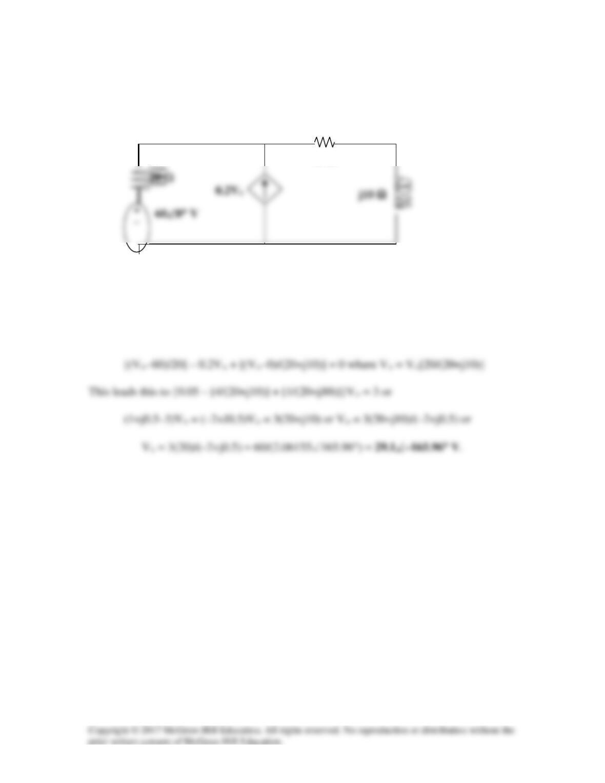
Solution 10.13
Nodal analysis is the best approach to use on this problem. We can make our work easier
by doing a source transformation on the right hand side of the circuit.
18 Ω
+
j6 Ω
–j2 Ω
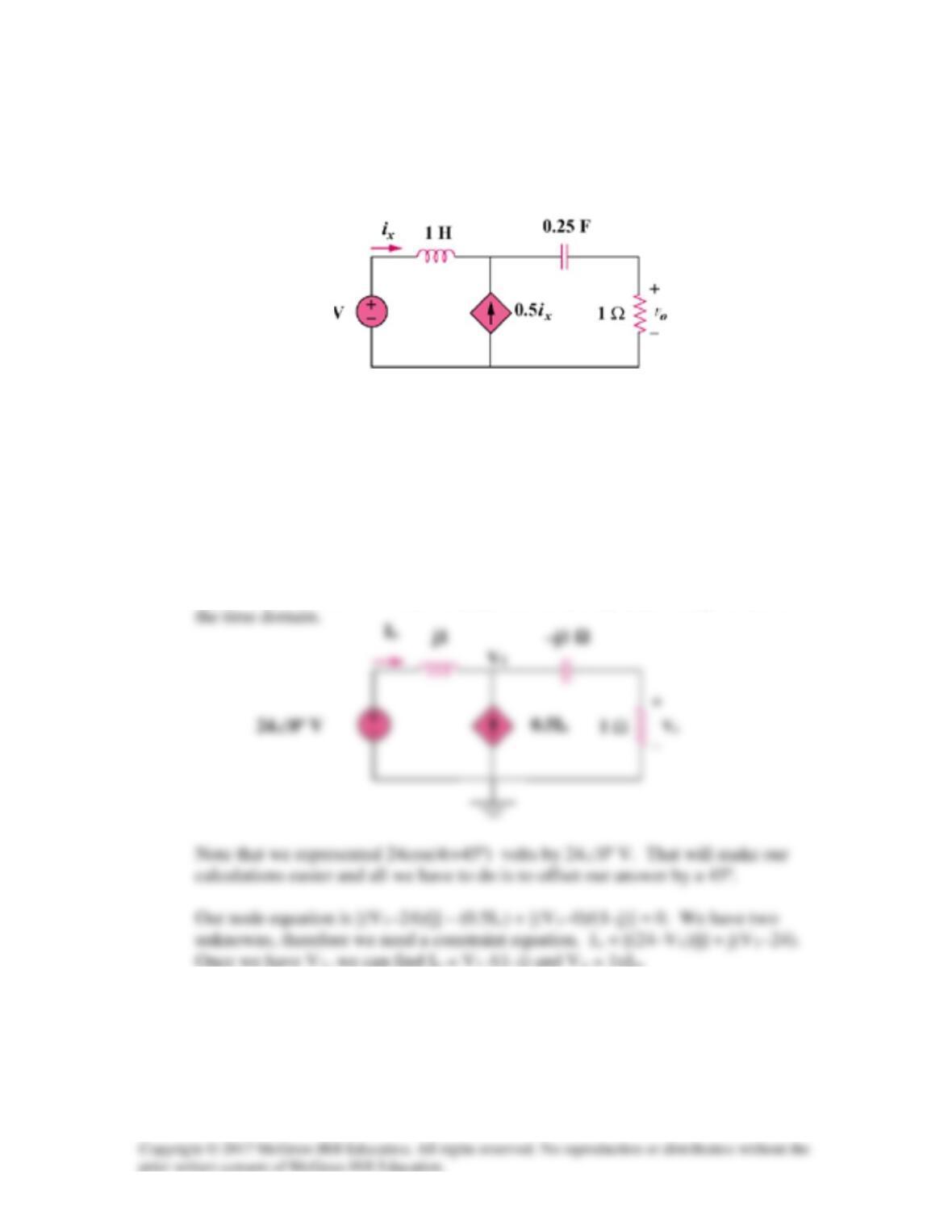
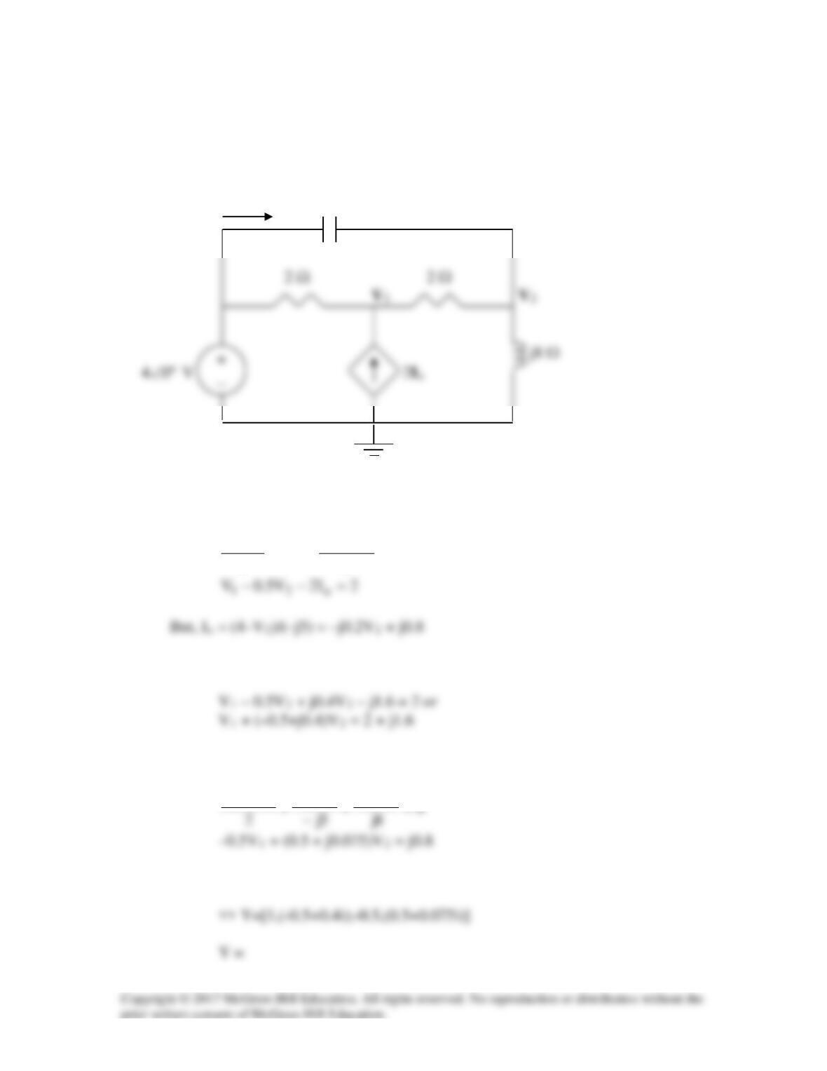
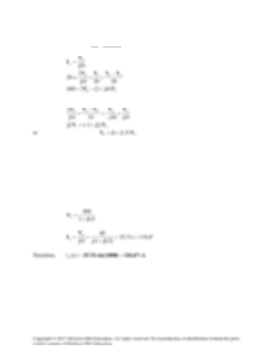
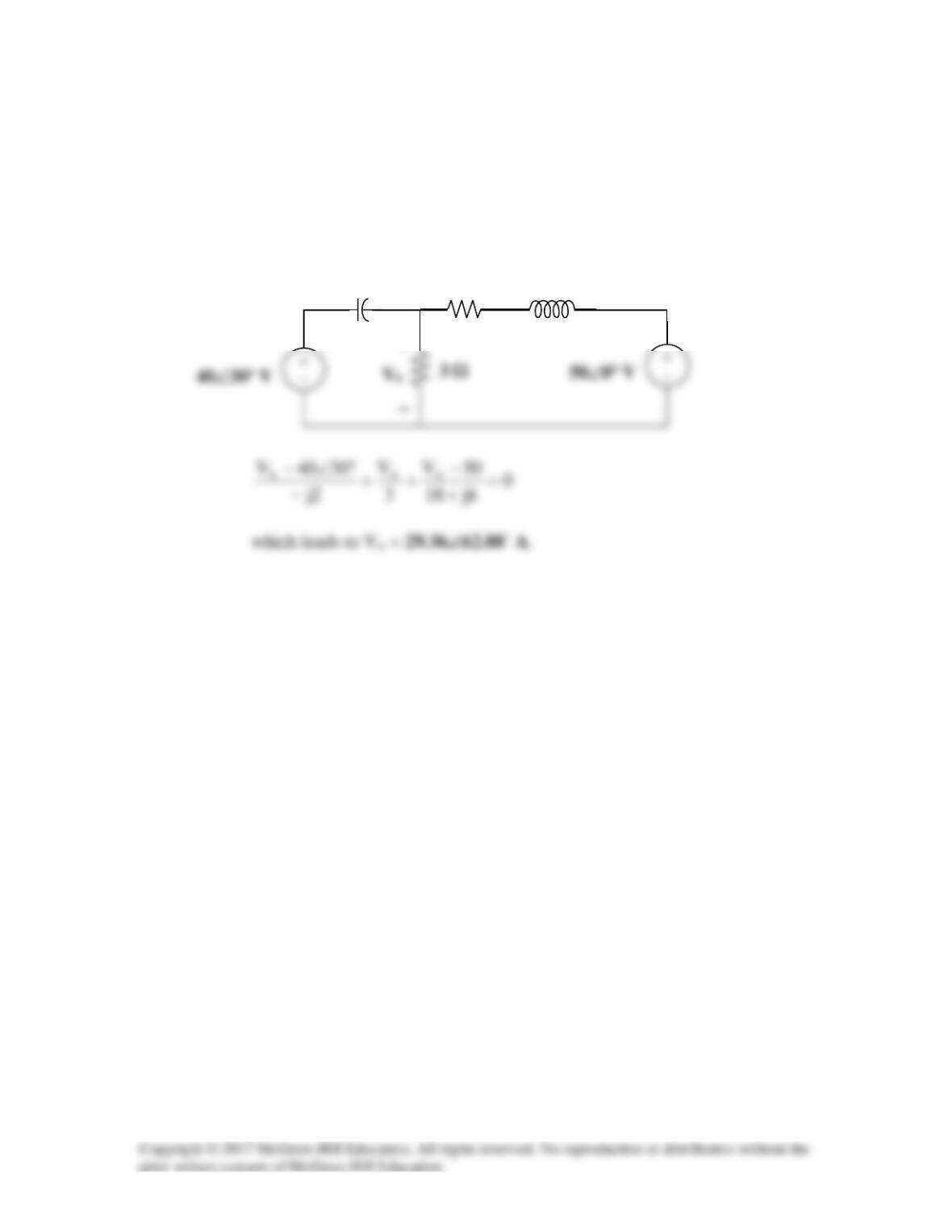
Solution 10.14
At node 1,
°∠=
−
+
−
+
−3020
4j10
0
2j–
0
1211
VVVV
At node 2,
−
1222
VVVV
Equations (1) and (2) can be cast into matrix form as
+
5.2j5.2j1
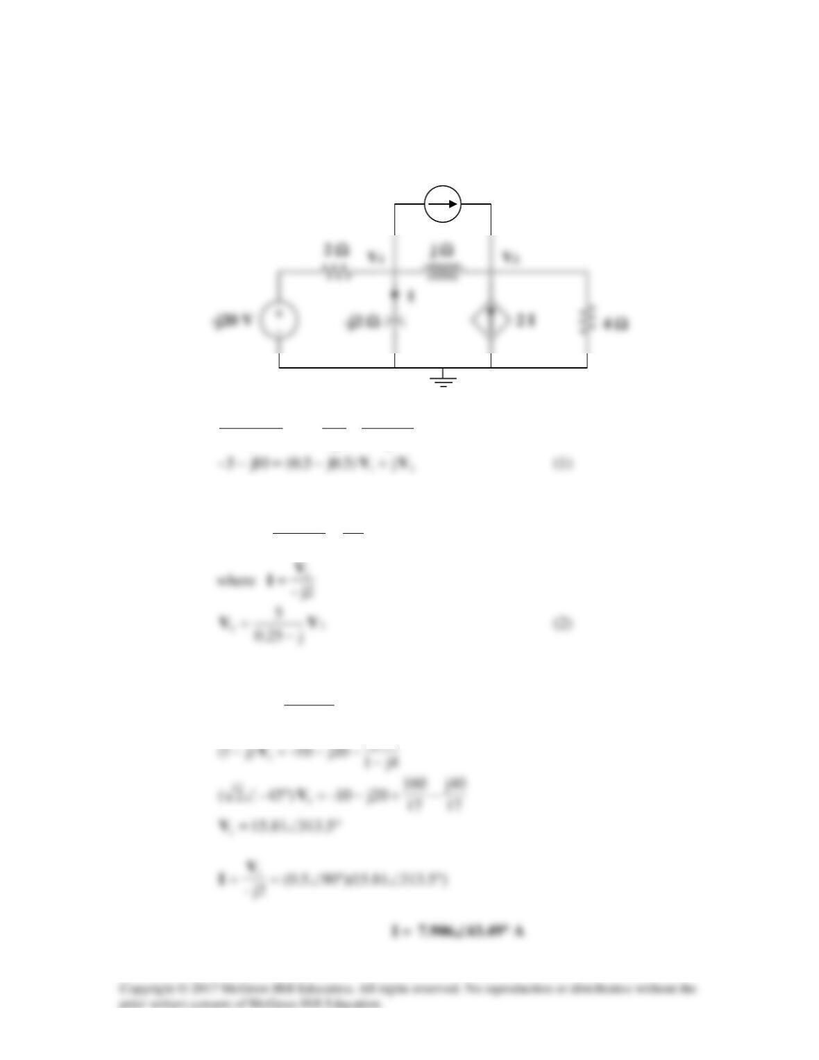
Solution 10.15
We apply nodal analysis to the circuit shown below.
At node 1,
j2j–
5
2
20j–
2111
VVVV −
++=
−
At node 2,
4j
25 221 VVV
I=
−
++
,
Substituting (2) into (1),
1
)j1(5.0
j25.0
5j
10j5– V−=
−
−−
40j
5 A
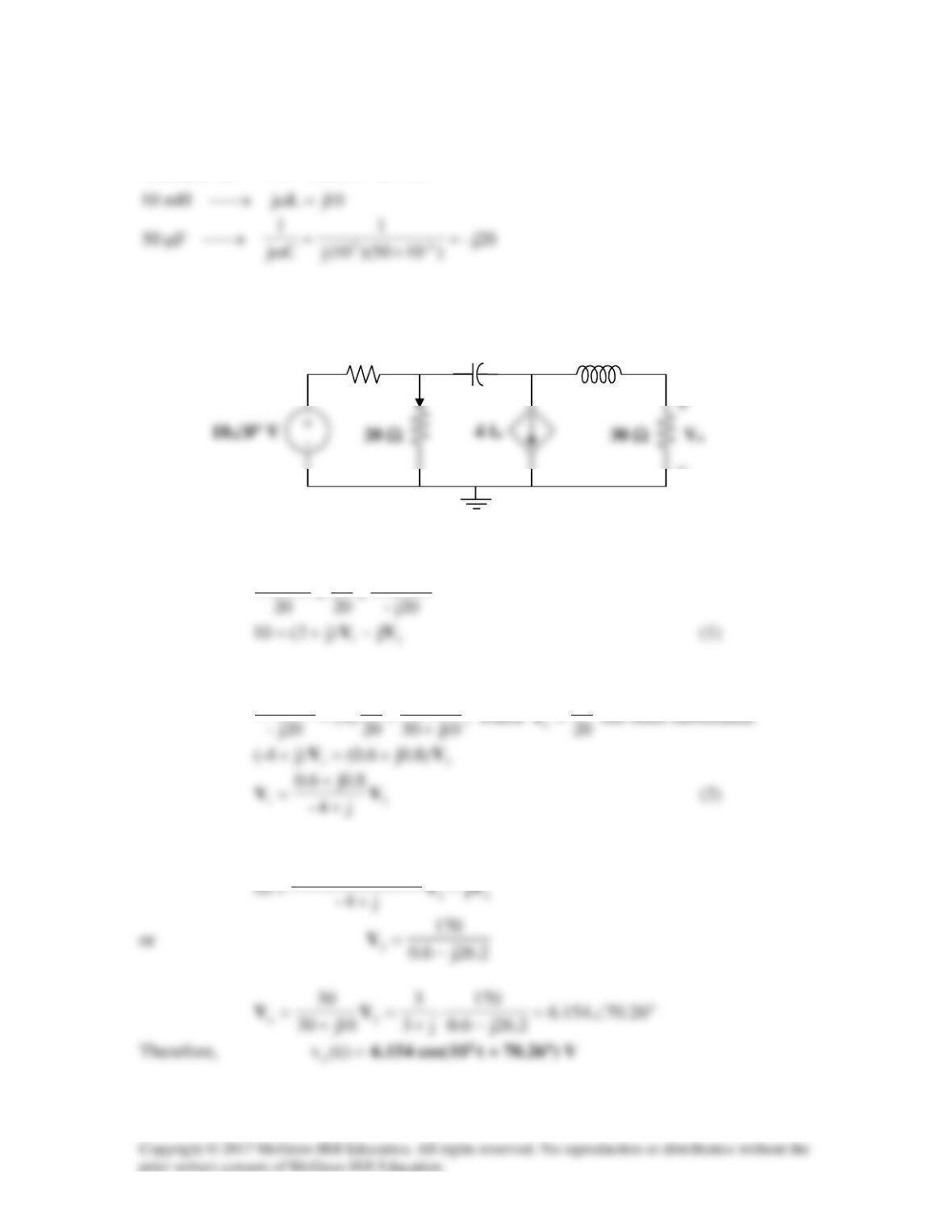
Solution 10.16
Consider the circuit as shown in the figure below.
V1 j4 Ω V2
At node 1,
0
4j
VV
5
0V
2
211
=
−
+
−
+−
(1)
At node 2,
0453
3j
0V
4j
VV
212
=°∠−
−
−
+
−
(2)
Solving this using MATLAB, we get,
>> Y=[(0.2-0.25i),0.25i;0.25i,0.08333i]