Solution 18.35
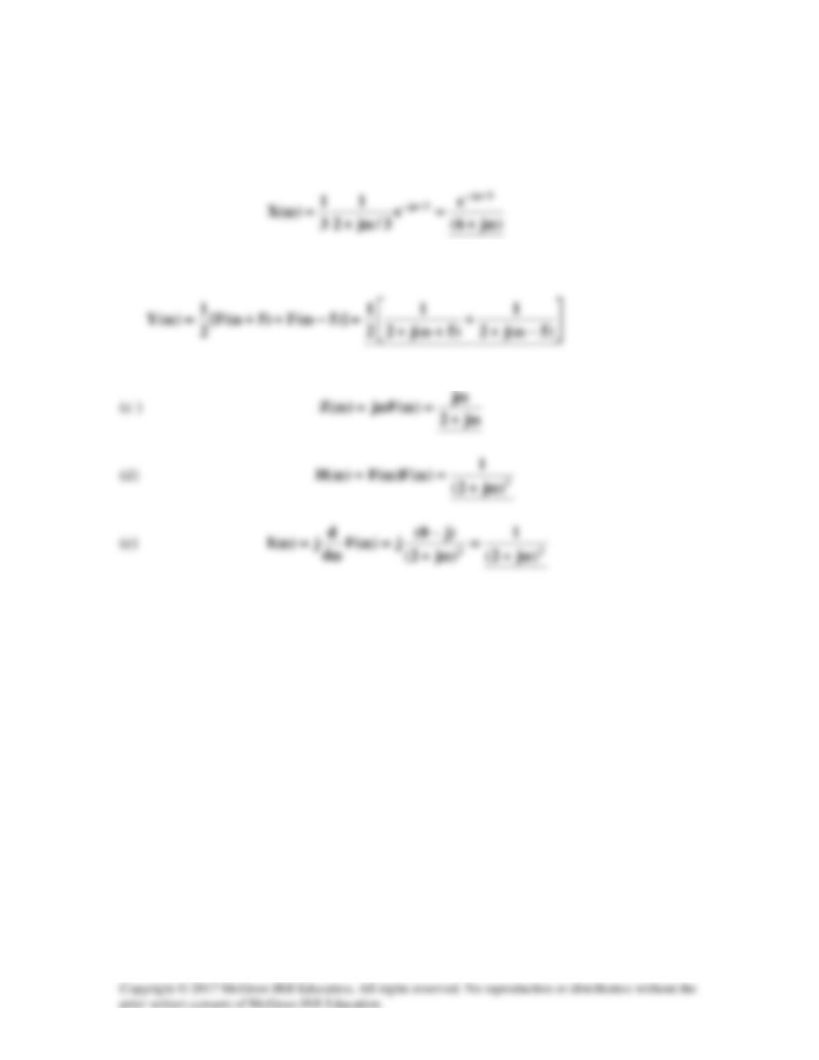
(a) x(t) = f[3(t-1/3)]. Using the scaling and time shifting properties,
(b) Using the modulation property,
Solution 18.36
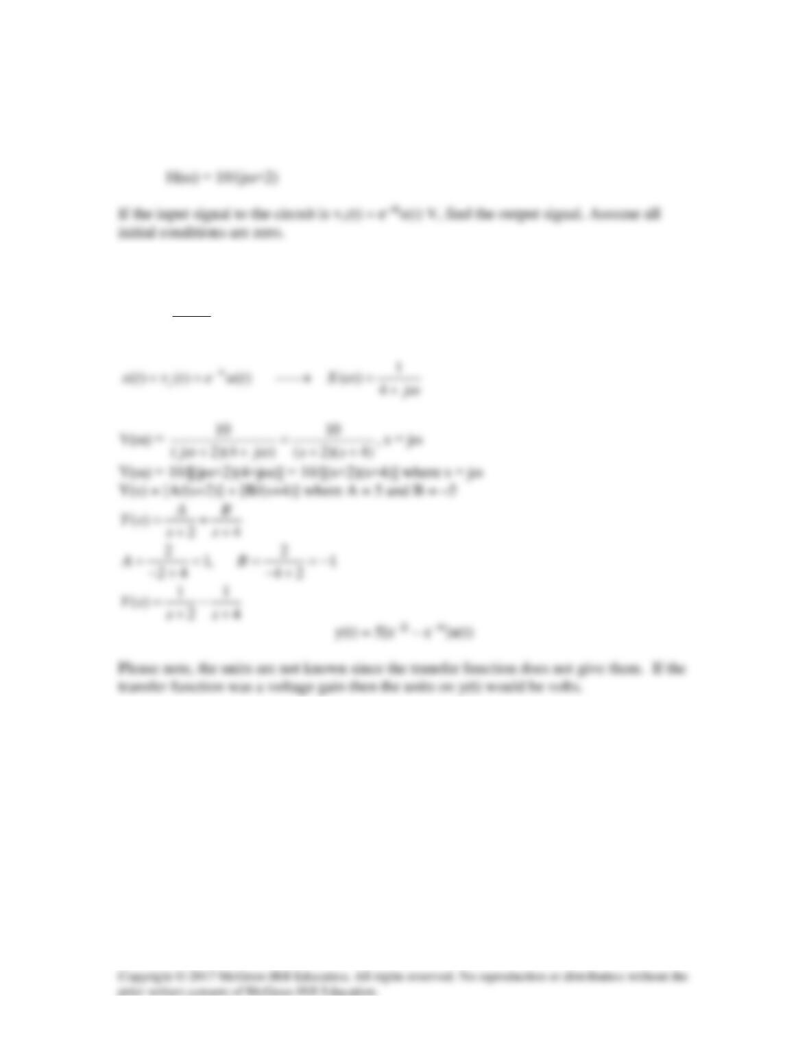
The transfer function of a circuit is
Solution
()
() () () ()
()
Y
H Y HX
X
ω
ω ω ωω
ω
= → =
Solution 18.37
By current division,
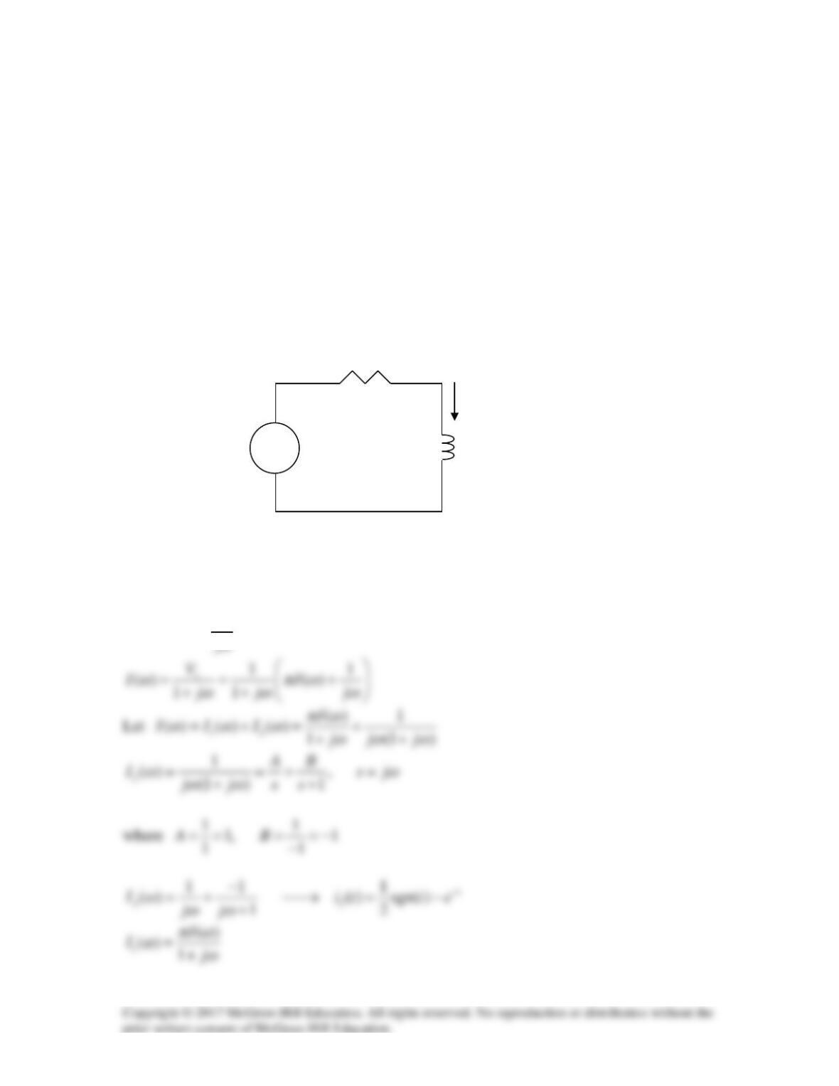
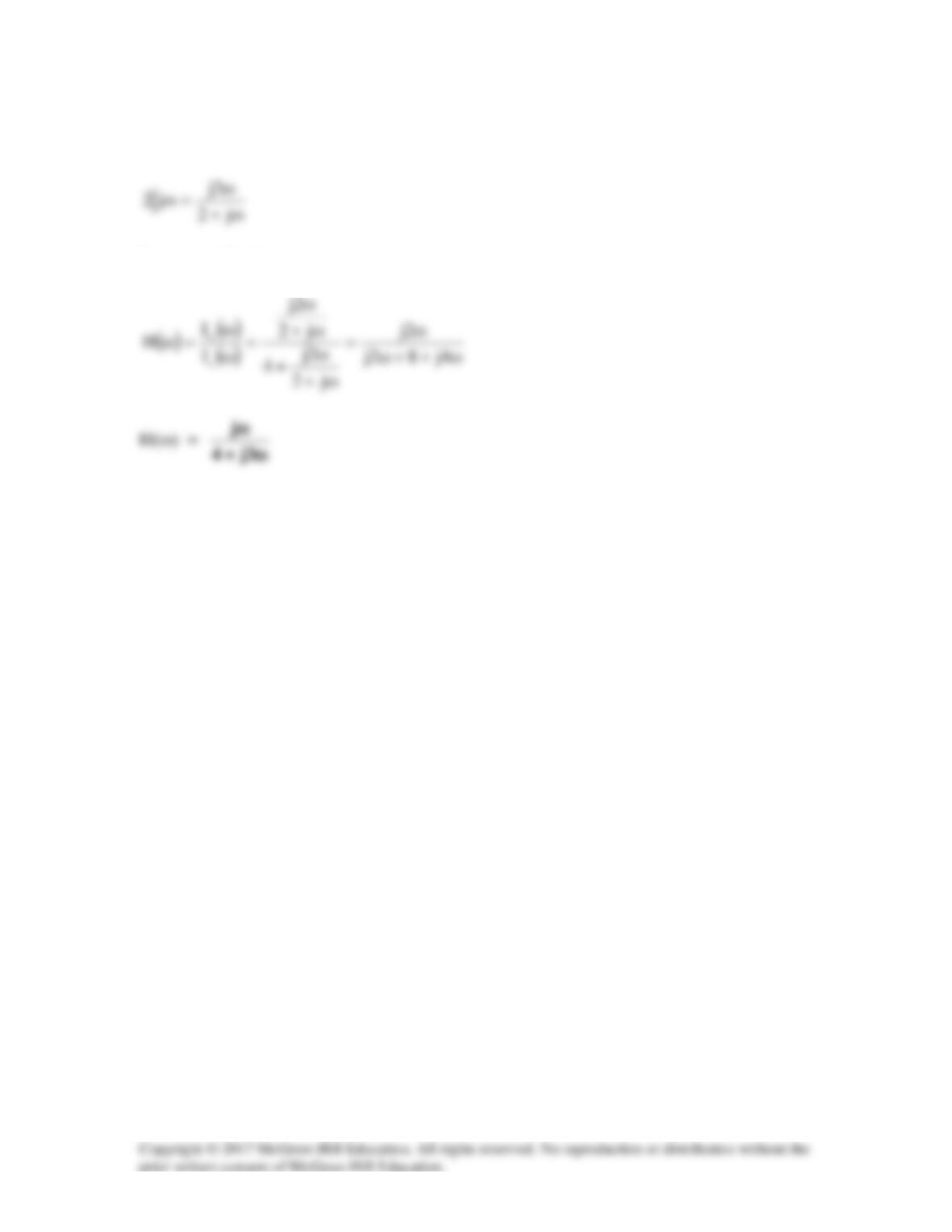
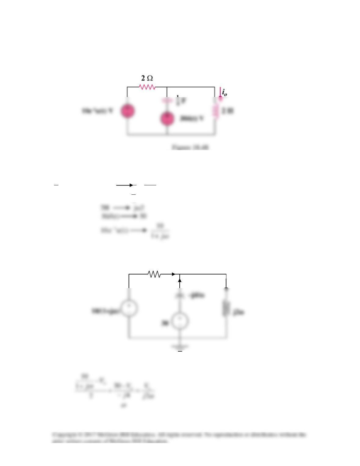
Solution 18.38
Using Fig. 18.40, design a problem to help other students to better understand using
Fourier transforms to do circuit analysis.
Although there are many ways to solve this problem, this is an example based on the
same kind of problem asked in the third edition.
Problem
Suppose vs(t) = u(t) for t>0. Determine i(t) in the circuit of Fig. 18.40 using Fourier
transform.
1 Ω
i
vs 1 H
Figure 18.40 For Prob. 18.38.
Solution
1
()
s
Vj
πδ ω ω
= +
+
_
Solution 18.39
Given the circuit in Fig. 18.41, with its excitation, determine the Fourier transform of i(t).
Figure 18.41
For Prob. 18.39.
Solution
ωω
jtj
−−
∞
555
Solution 18.40
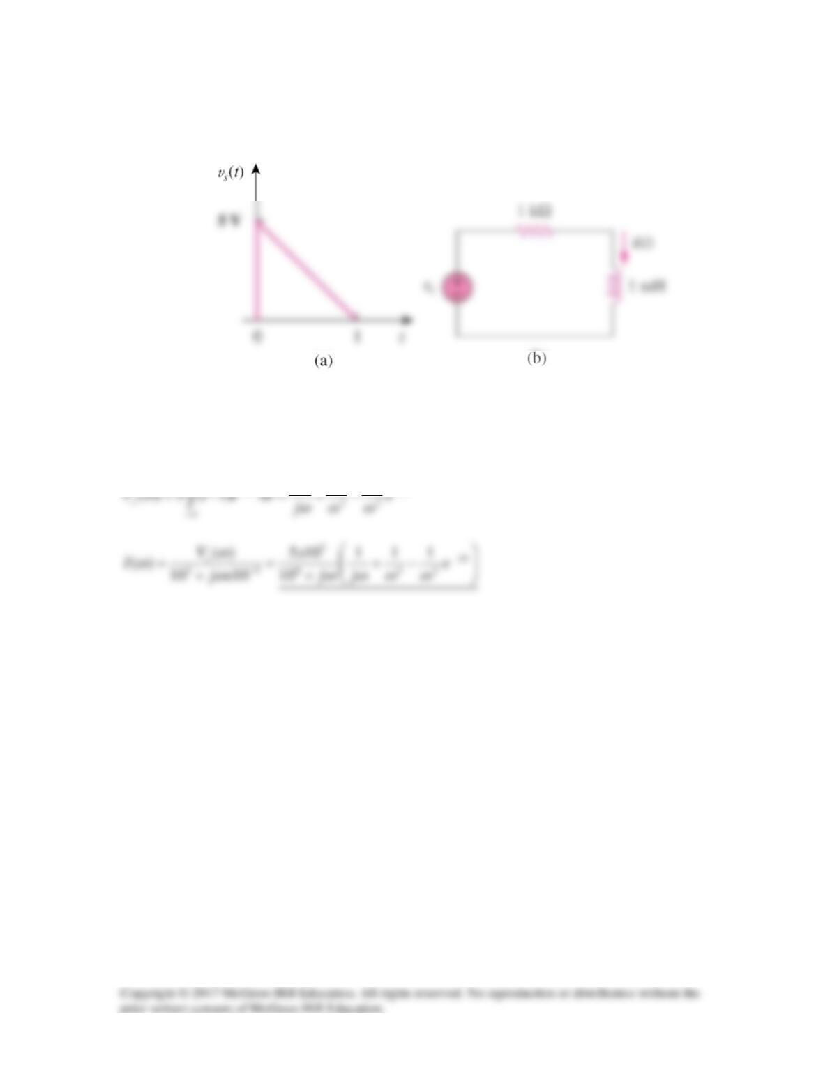
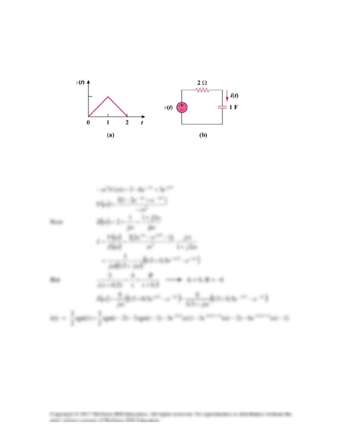
Determine the current i(t) in the circuit of Fig. 18.42(b), given the voltage source shown
in Fig. 18.42(a).
Figure 18.42
For Prob. 18.49.
Solution
)2(3)1(6)(3)( −+−−= tttt
v
δδδ
3 V
Solution 18.41
2
Solution 18.42
By current division,
( )
ω⋅
ω+
=I
j2
2
Io
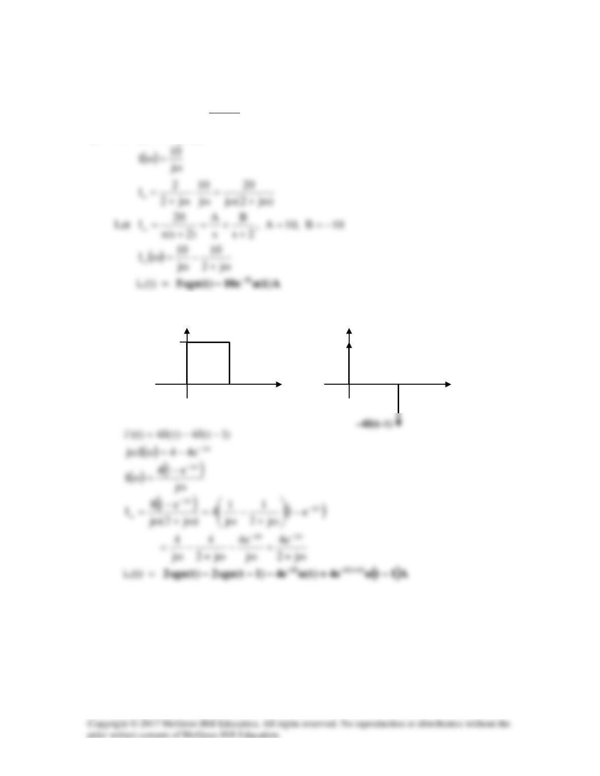
(a) For i(t) = 5 sgn (t),
(b)
1
t
i’(t)
4δ(t)
1
t
i(t)
4
Solution 18.43
ω+
=→=
ω
=
ω
=
ω
→ −
−j1
5
Ie5i,
j
50
10x20j
1
Cj
1
mF 20 s
t
s
3
Solution 18.44
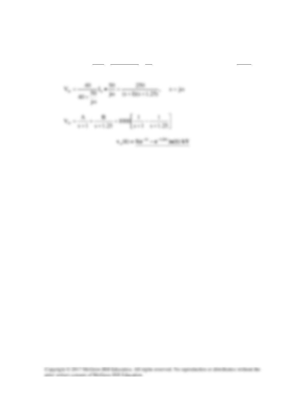
If the rectangular pulse in Fig. 18.46(a) is applied to the circuit in Fig. 18.46(b), find vo at
t = 1 s.
Figure 18.46
For Prob. 18.44.
Solution
1H jω
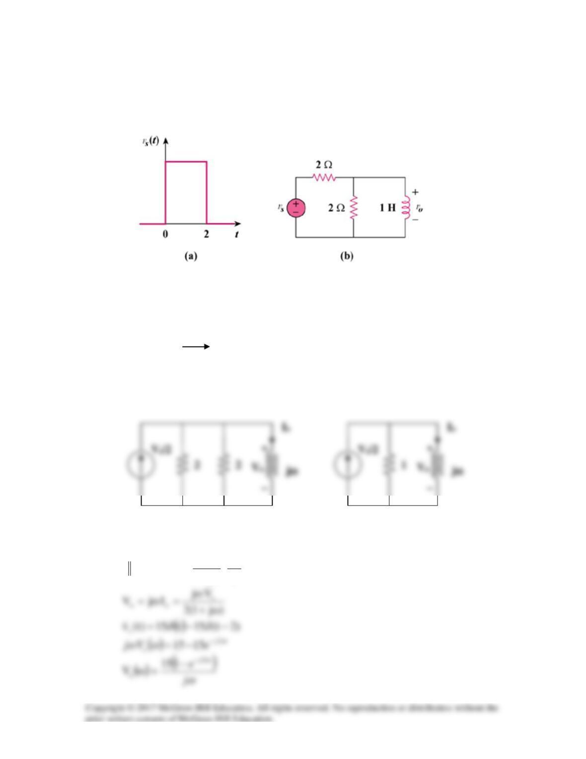
We transform the voltage source to a current source as shown in Fig. (a) and then
combine the two parallel 2Ω resistors, as shown in Fig. (b).
,122 Ω=
2
V
j1
1
Is
o⋅
ω+
=
(a)
(b)
15 V

( )
ω
ω
2
2
5.7
5.7
15.7
j
j
e
−
−
−
Solution 18.45
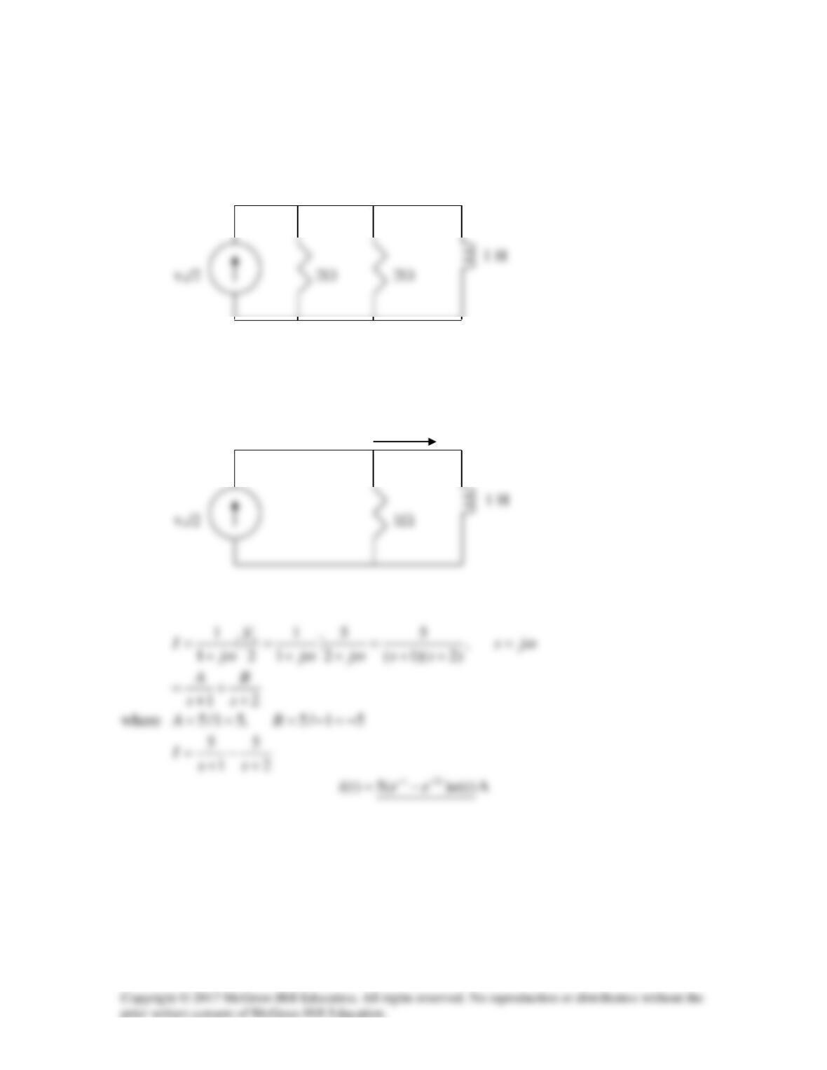
We may convert the voltage source to a current source as shown below.
Combining the two 2-Ω resistors gives 1 Ω. The circuit now becomes that shown
below.
I
Solution 18.46
Determine the Fourier transform of io(t) in the circuit of Fig. 18.48.
For Prob. 18.46.
Solution
F
4
1
ω
−
=
ω
4j
1
j
1
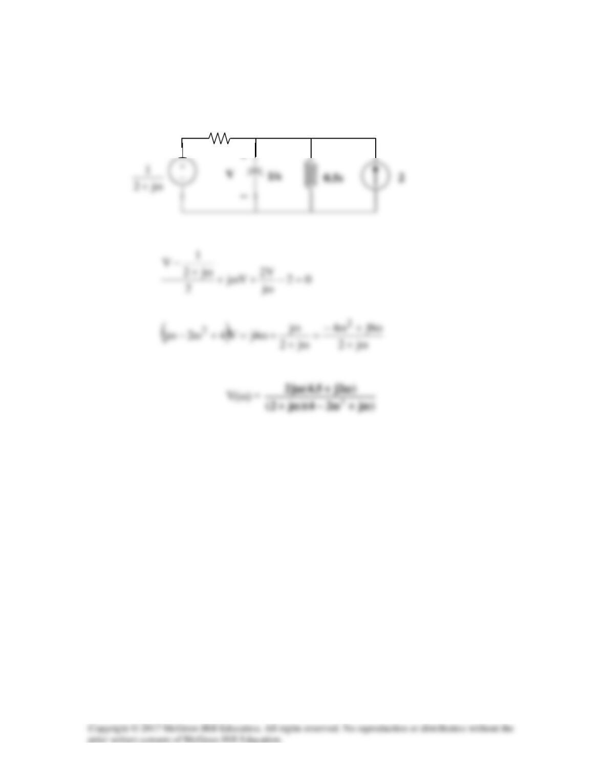
The circuit in the frequency domain is shown below:
At node Vo, KCL gives
Io(ω)
2 Ω
Vo
ωω
ωω
ω
ωω
)3j32(10
)3j32(10
j1
3030j20
V
2
2
2
o
−+
−+
+
−+
Solution 18.47
1 12
2FjC j
ωω
→ =
Solution 18.48
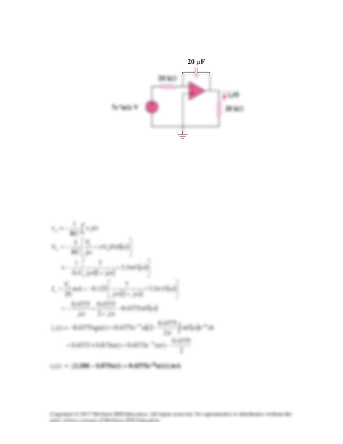
Find io(t) in the op amp circuit of Fig. 18.50.
Figure 18.50
For Prob. 18.48.
Solution
As an integrator,
4.010x20x10x20RC 63 == −
Solution 18.49
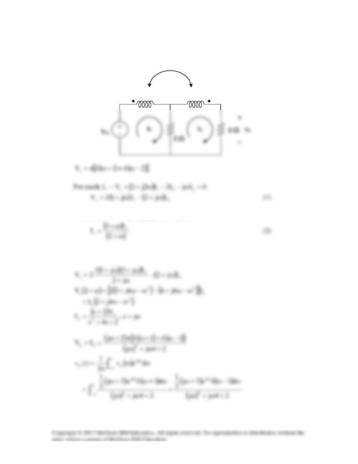
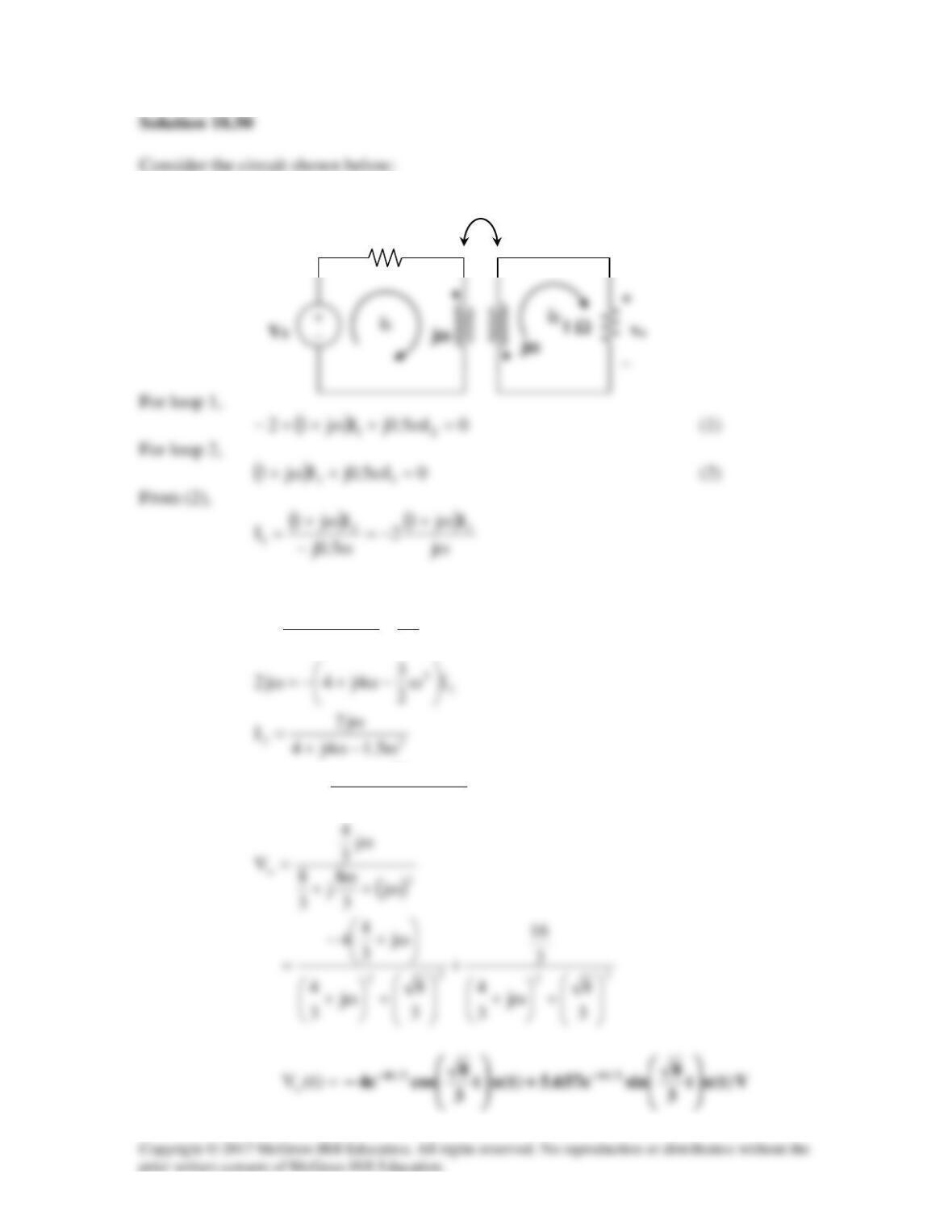
Consider the circuit shown below:
For mesh 2,
( )
112 IjI2Ij30 ω−−ω+=
Substituting (2) into (1) gives
jω
j2ω
jω
( ) ( )
e2j
1
e2j
1
jtjt
+
+−
Substituting this into (1),
( )
2
2
I
2
j
j
Ij12
2ω
+
ω
ω+−
=
( )
2
2o
j5.14j4
j2
IV ω+ω+
ω−
==
1 Ω
j0.5ω