Solution 12.56
Using Fig. 12.63, design a problem to help other students to better understand unbalanced
three–phase systems.
Although there are many ways to solve this problem, this is an example based on the
same kind of problem asked in the third edition.
Problem
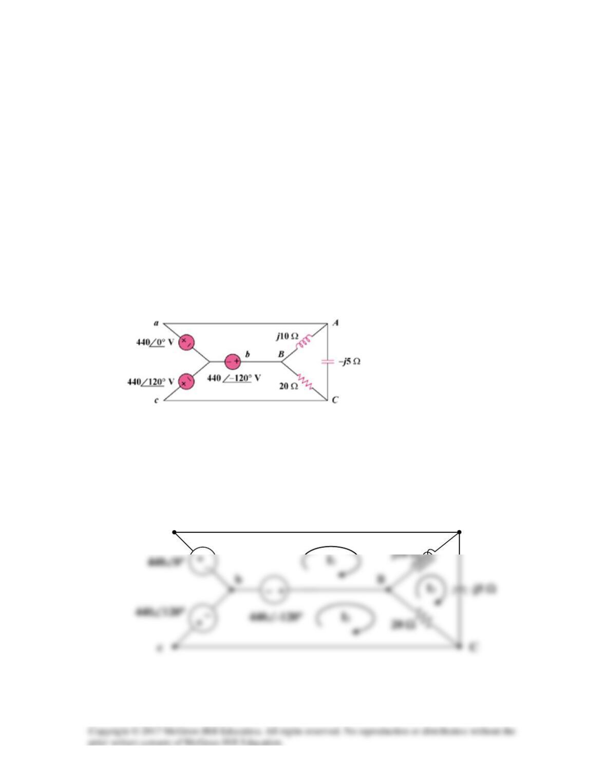
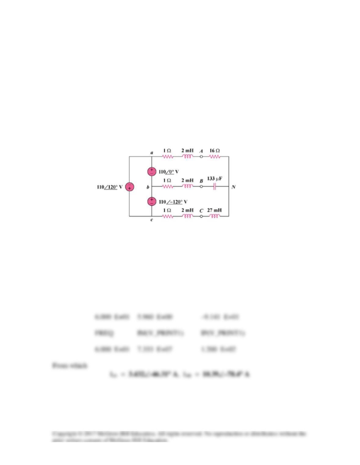
Refer to the unbalanced circuit of Fig. 12.63. Calculate:
(a) the line currents
(b) the real power absorbed by the load
(c) the total complex power supplied by the source
Figure 12.63
Solution
(a) Consider the circuit below.
C
B
b
c
A
a
For mesh 1,
0)(10j0440120–440 31 =−+°∠−°∠ II
For mesh 2,
0)(20120–440120440
32
=−+°∠−°∠ II
Substituting (1) and (2) into the equation for mesh 3 gives,
From (1),
==
1a
II
A30132 °∠
(b)
kVA08.58j)10j(
2
31AB =−= IIS
(c) Total complex supplied by the source is
Solution 12.57
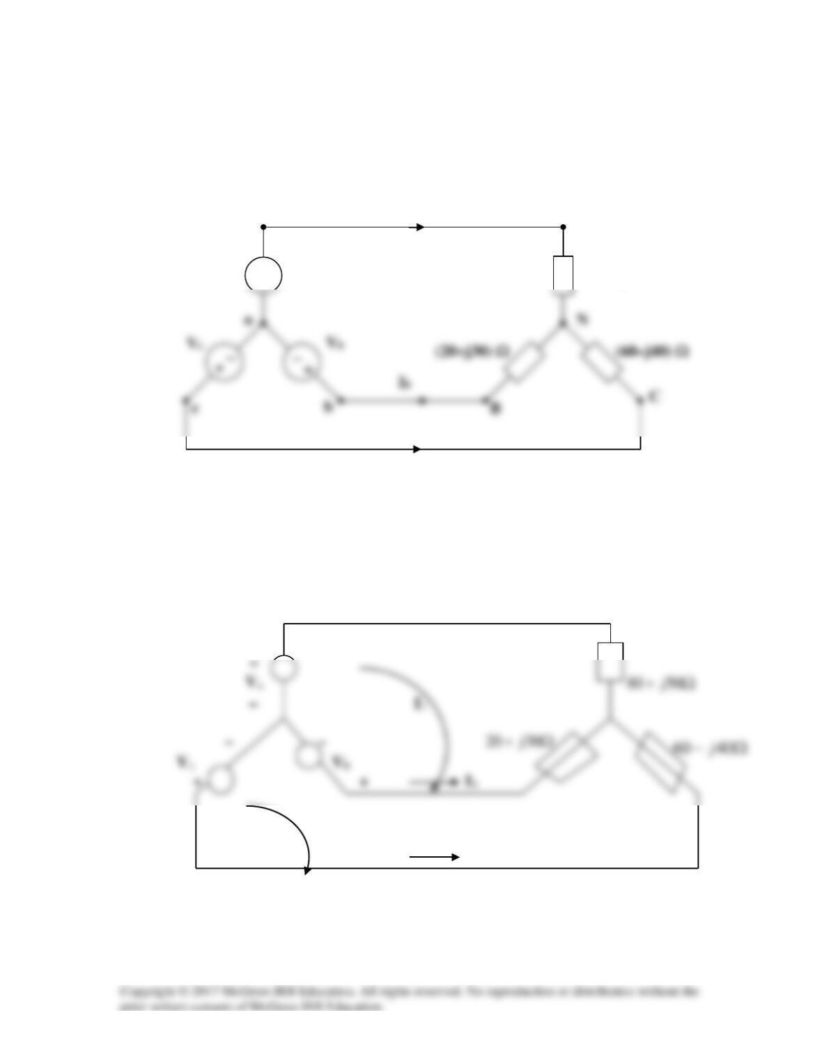
Determine the line currents for the three-phase circuit in Fig. 12.64.
Let Va =220∠0°, Vb = 220∠–120°, Vc = 220∠120° V.
b
N
Ib
Figure 12.64
For Prob. 12.57.
Solution
We apply mesh analysis to the circuit shown below.
Ia
I2
Ic
Ia
(80+ j60) Ω
A
Ic
+
Va
a
Va = 220 V, Vb = (–110 – j190.53) V, Vc = (–110 + j190.53) V
Solving (1) and (2) using MATLAB gives,
V =
1.0e+02 *
I =
3.7233 – 1.2170i
1.8178 – 3.4445i or
Solution 12.58
The schematic is shown below. IPRINT is inserted in the neutral line to measure the
current through the line. In the AC Sweep box, we select Total Ptss = 1,
Start Freq. = 0.1592, and End Freq. = 0.1592. After simulation, the output file
includes
FREQ IM(V_PRINT4) IP(V_PRINT4)
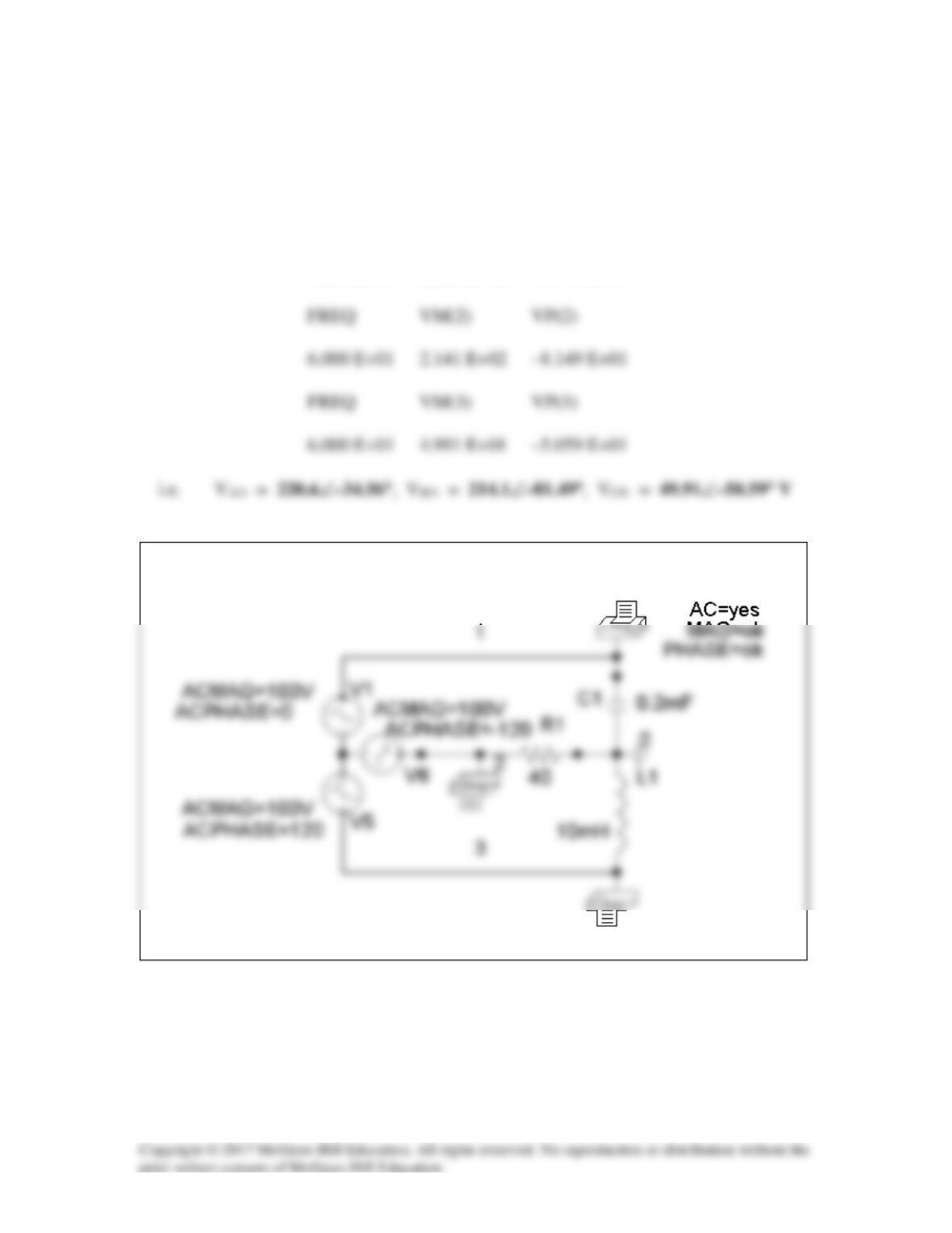
Solution 12.59
The schematic is shown below. In the AC Sweep box, we set Total Pts = 1, Start Freq
= 60, and End Freq = 60. After simulation, we obtain an output file which includes
FREQ VM(1) VP(1)
6.000 E+01 2.206 E+02 –3.456 E+01
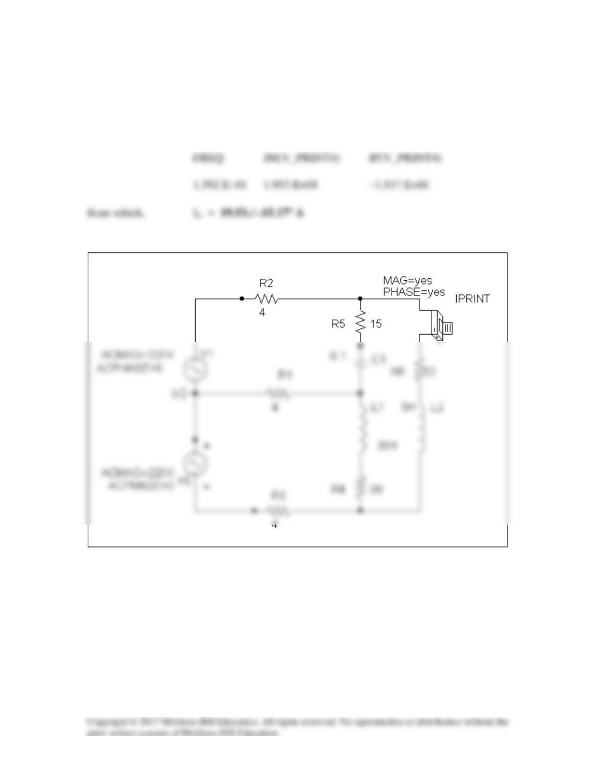
Solution 12.60
The schematic is shown below. IPRINT is inserted to give Io. We select Total Pts = 1,
Start Freq = 0.1592, and End Freq = 0.1592 in the AC Sweep box. Upon simulation,
the output file includes
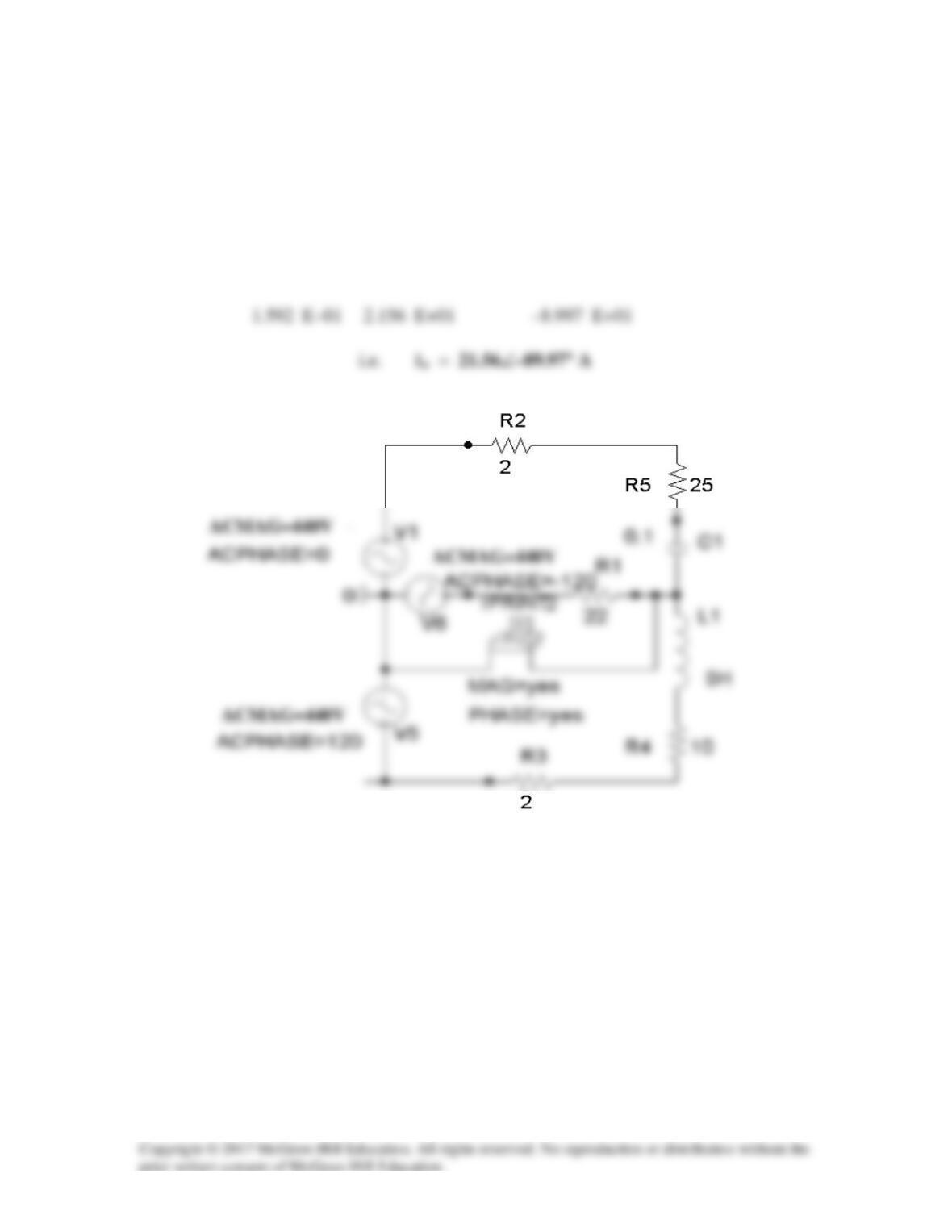
Solution 12.61
The schematic is shown below. Pseudo-components IPRINT and PRINT are inserted to
measure IaA and VBN. In the AC Sweep box, we set Total Pts = 1, Start Freq = 0.1592,
and End Freq = 0.1592. Once the circuit is simulated, we get an output file which
includes
FREQ VM(2) VP(2)
from which
Solution 12.62
Using Fig. 12.68, design a problem to help other students to better understand how to use
PSpice to analyze three–phase circuits.
Although there are many ways to solve this problem, this is an example based on the
same kind of problem asked in the third edition.
Problem
The circuit in Fig. 12.68 operates at 60 Hz. Use PSpice to find the source current Iab and
the line current IbB.
Figure 12.68
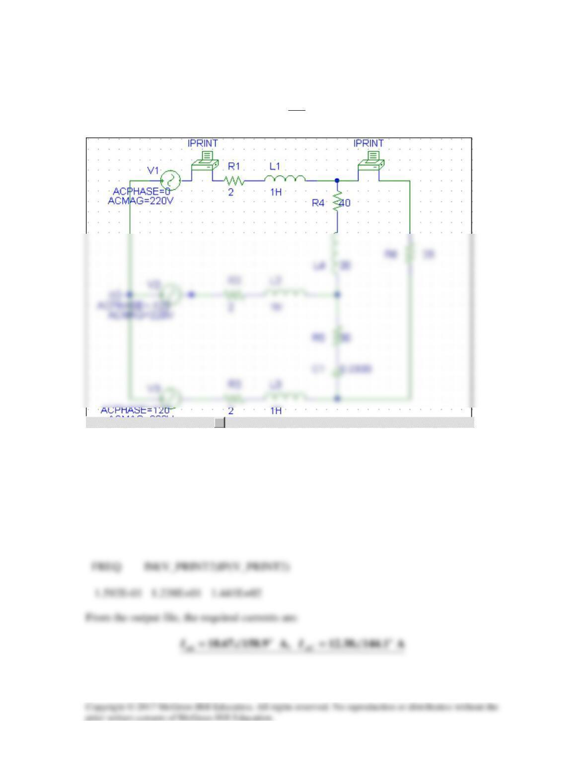
Solution
Because of the delta-connected source involved, we follow Example 12.12. In the AC
Sweep box, we type Total Pts = 1, Start Freq = 60, and End Freq = 60. After
simulation, the output file includes
FREQ IM(V_PRINT2) IP(V_PRINT2)
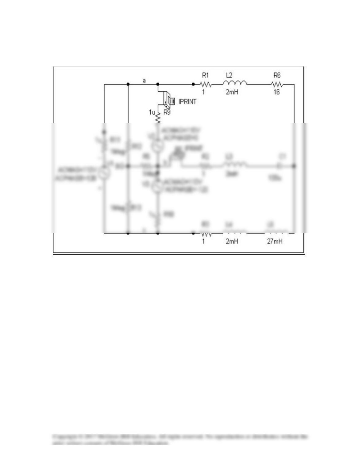
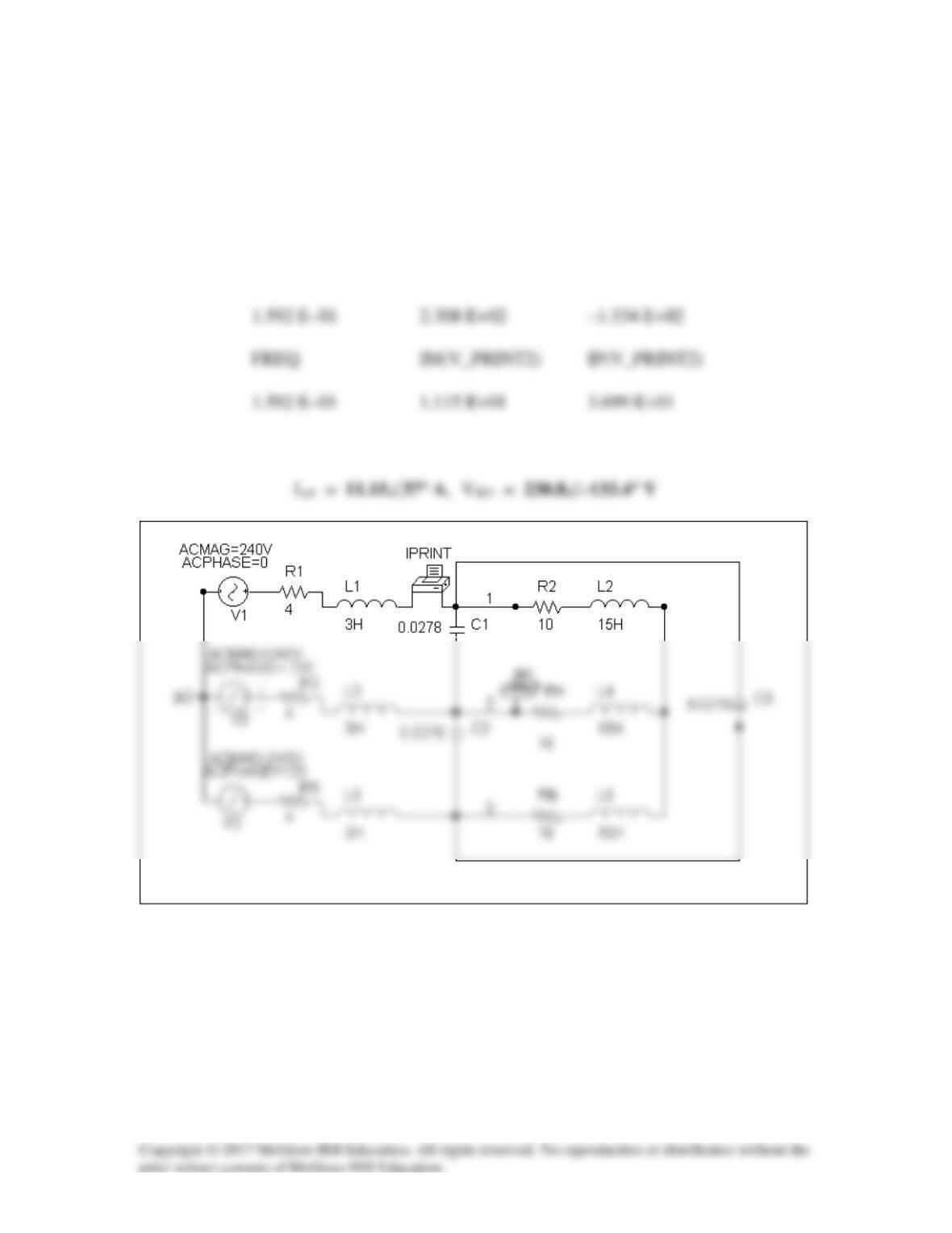
Solution 12.63
Let
F 0333.0
X
1
C and H, 20X/ L that so 1 =====
ω
ωω
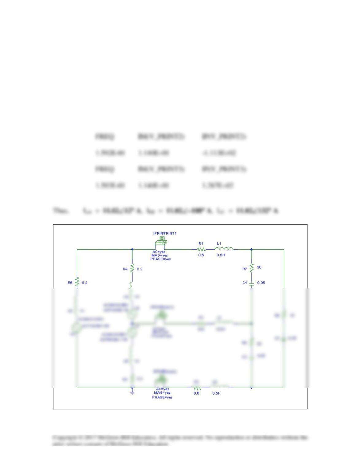
The schematic is shown below..
.
When the file is saved and run, we obtain an output file which includes the following:
FREQ IM(V_PRINT1)IP(V_PRINT1)
1.592E-01 1.867E+01 1.589E+02
Solution 12.64
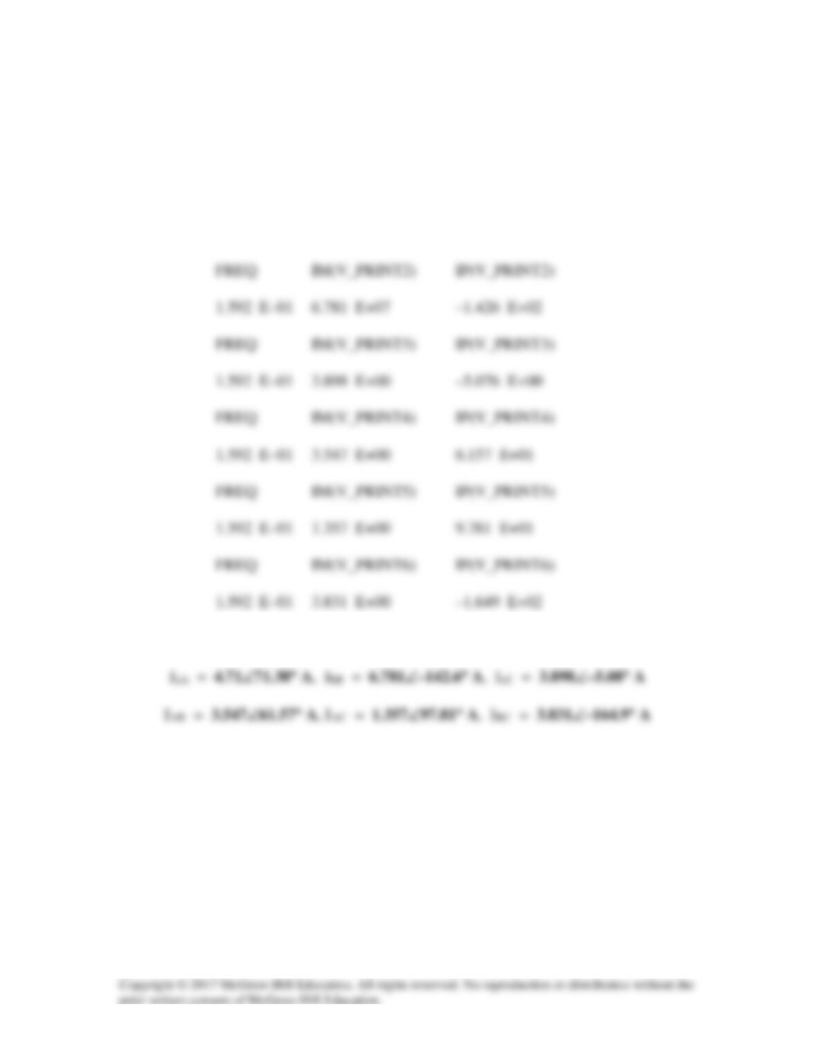
We follow Example 12.12. In the AC Sweep box we type Total Pts = 1,
Start Freq = 0.1592, and End Freq = 0.1592. After simulation the output file includes
FREQ IM(V_PRINT1) IP(V_PRINT1)
1.592 E–01 4.710 E+00 7.138 E+01
from this we obtain
Solution 12.65
Due to the delta-connected source, we follow Example 12.12. We type Total Pts = 1,
Start Freq = 0.1592, and End Freq = 0.1592. The schematic is shown below. After it
is saved and simulated, we obtain an output file which includes
FREQ IM(V_PRINT1) IP(V_PRINT1)
1.592E-01 1.140E+01 8.664E+00
Since this is a balanced circuit, we can perform a quick check. The load resistance is
large compared to the line and source impedances so we will ignore them (although it
would not be difficult to include them).
Converting the sources to a Y configuration we get:
Van = 138.56 ∠–20˚ Vrms
and
Solution 12.66
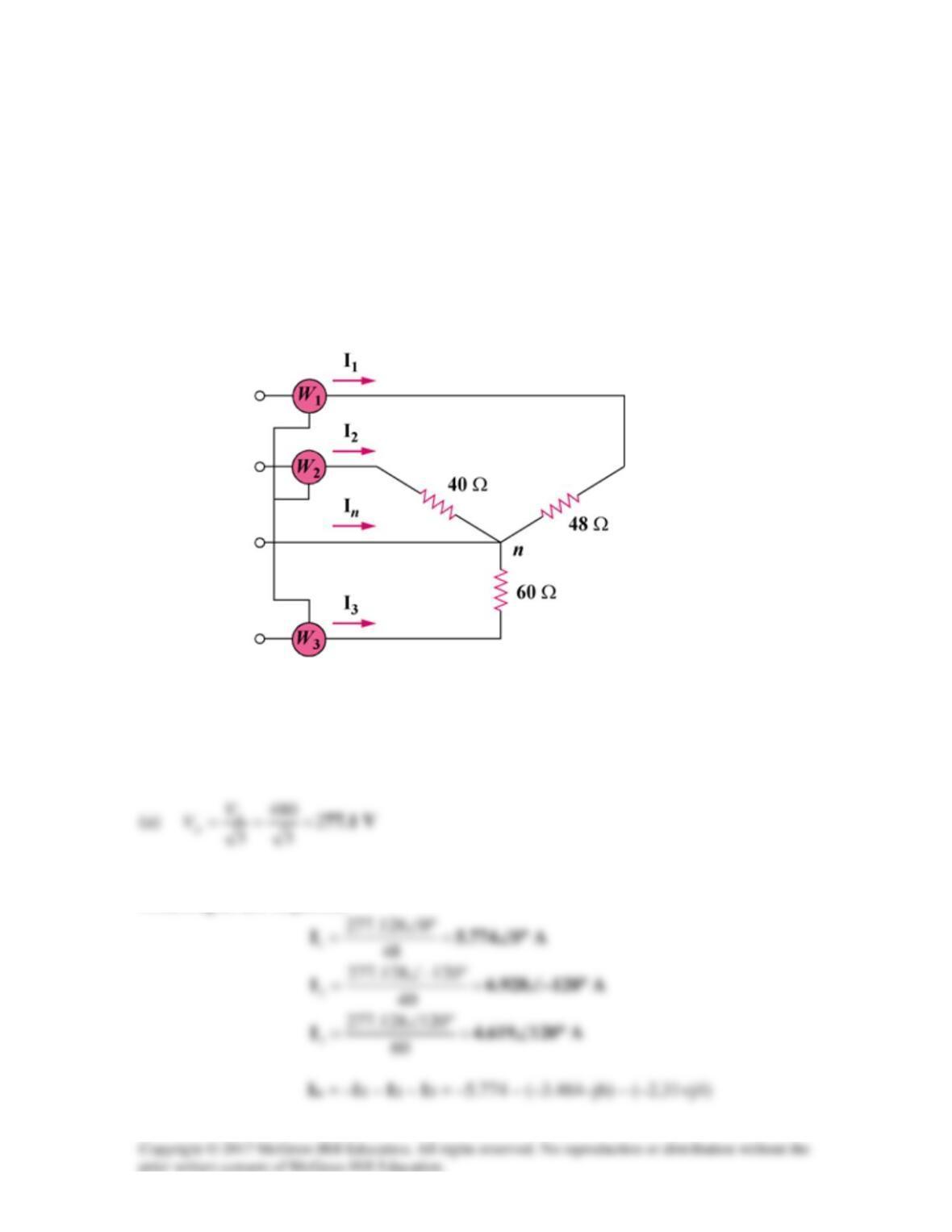
A three-phase, four-wire system operating with a 480-V line voltage is shown in
Fig. 12.71. The source voltages are balanced. The power absorbed by the resistive wye-
connected load is measured by the three–wattmeter method. Calculate:
(a) the voltage to neutral
(b) the currents I1, I2, I3, and In
(c) the readings of the wattmeters
(d) the total power absorbed by the load
Figure 12.71
For Prob. 12.66.
Solution
(b) Because the load is unbalanced, we have an unbalanced three–phase system.
Assuming an abc sequence,
(c)
=== )48()774.5(
2
1
2
11
RIP
1.6003 kW
Solution 12.67
The motor power per phase is
Hence, the wattmeter readings are as follows:
=+= 2467.73Wa
kW67.97
kW67.88
(b) The motor load is balanced so that
0I
N
=
.
For the lighting loads,
A200
000,24
Ia==
If we let
A02000I
aa
°∠=°∠=I
Solution 12.68
(b)
S
P
cospfcosSP =θ=→θ=
Solution 12.69
For load 1,
11 11 1
cos sinS S jS
θθ
= +
Therefore,