Solution 19.1
Obtain the z parameters for the network in Fig. 19.65.
10 Ω
Figure 19.65
For Prob. 19.1.
Solution
Step 1. Label the circuit to allow us to determine the z–parameters.
10 Ω
10 Ω
10 Ω
10 Ω
I1
+
+
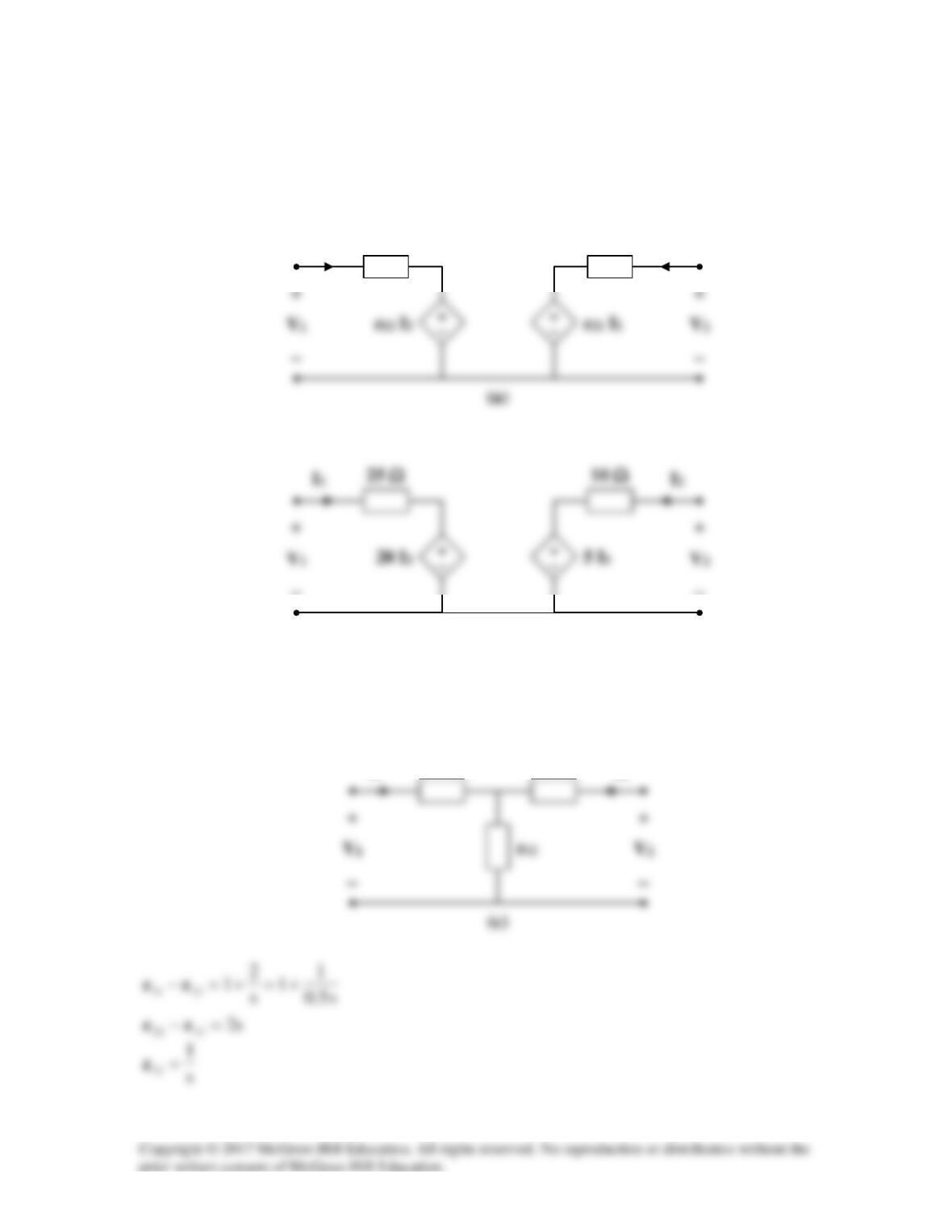
Solution 19.2
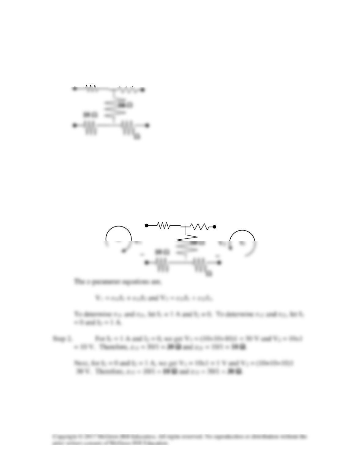
Consider the circuit in Fig. (a) to get
11
z
and
21
z
.
])12(||12[||12
1
1
11 +++== I
V
z
I2 = 0
1 Ω
+
1 Ω
(a)
Io
+
1 Ω
Io‘
1 Ω
To get
22
z
, consider the circuit in Fig. (b).
1 Ω
1 Ω
(b)
1 Ω
1 Ω
I1 = 0
Solution 19.3
Find the z parameters of the circuit in Fig. 19.67.
Figure 19.67
For Prob. 19.3.
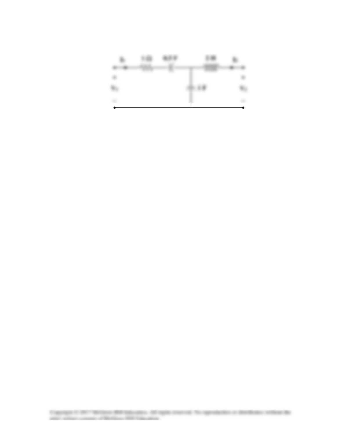
Solution
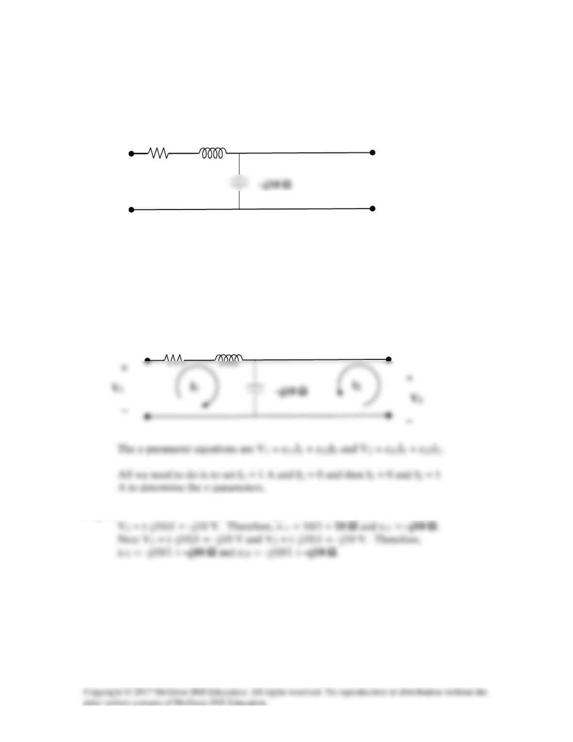
Step 1. All we need to do is to set up the circuit description and solve for the z-
parameters.
Step 2. For I1 = 1 A and I2 = 0 we get V1 = (10+j10–j10)1 = 10 V and
j10 Ω
10 Ω
j10 Ω
10 Ω
Solution 19.4
Using Fig. 19.68, design a problem to help other students to better understand how to
determine z parameters from an electrical circuit.
Although there are many ways to solve this problem, this is an example based on the
same kind of problem asked in the third edition.
Problem
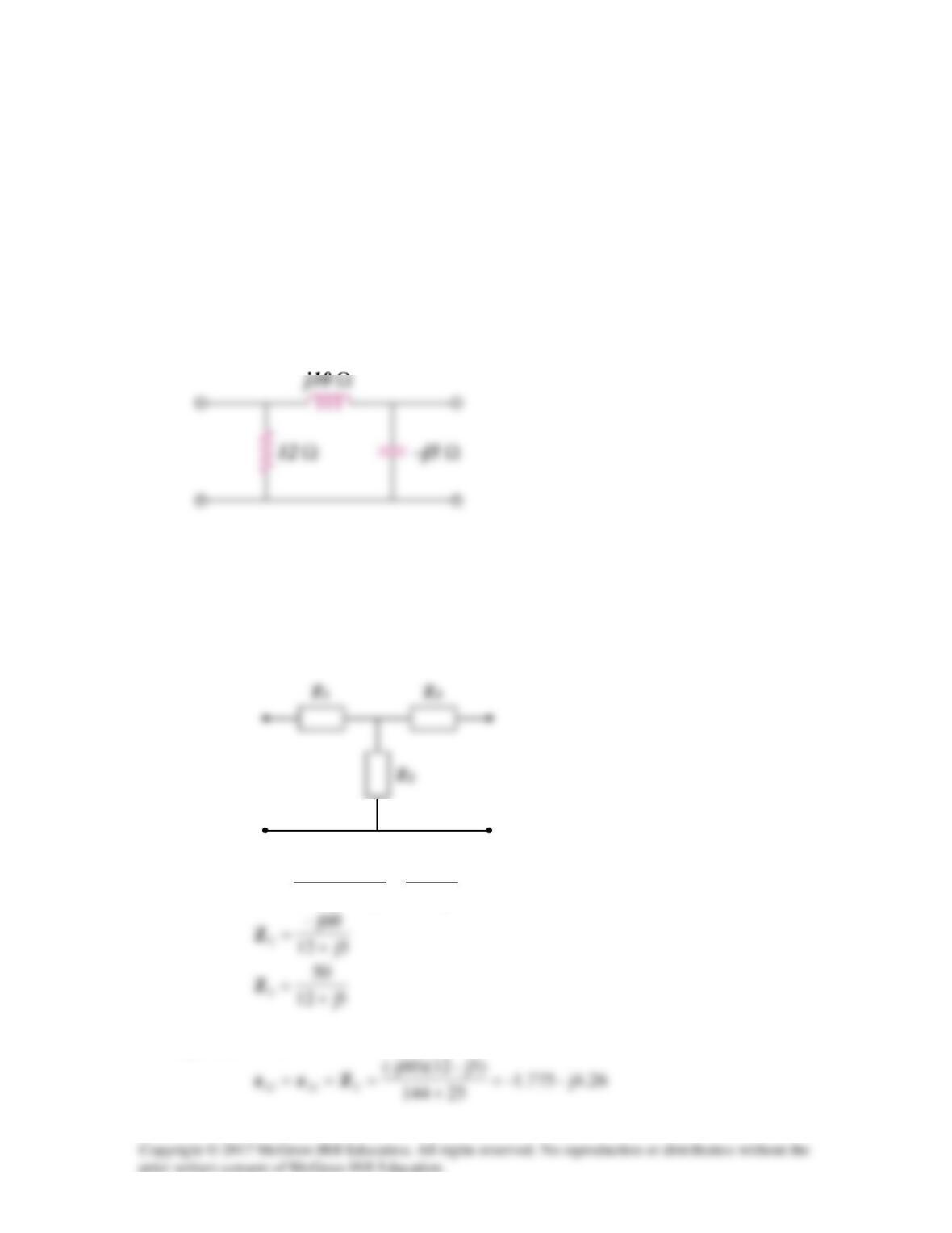
Calculate the z parameters for the circuit in Fig.19.68.
Figure 19.68
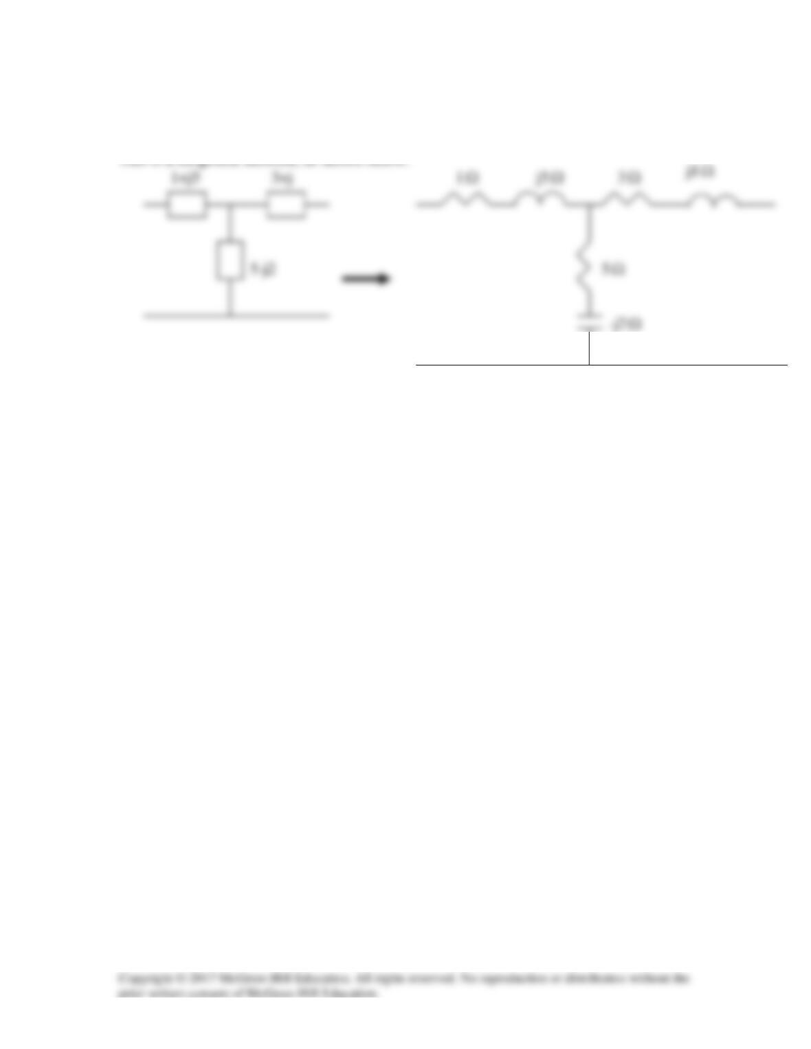
Solution
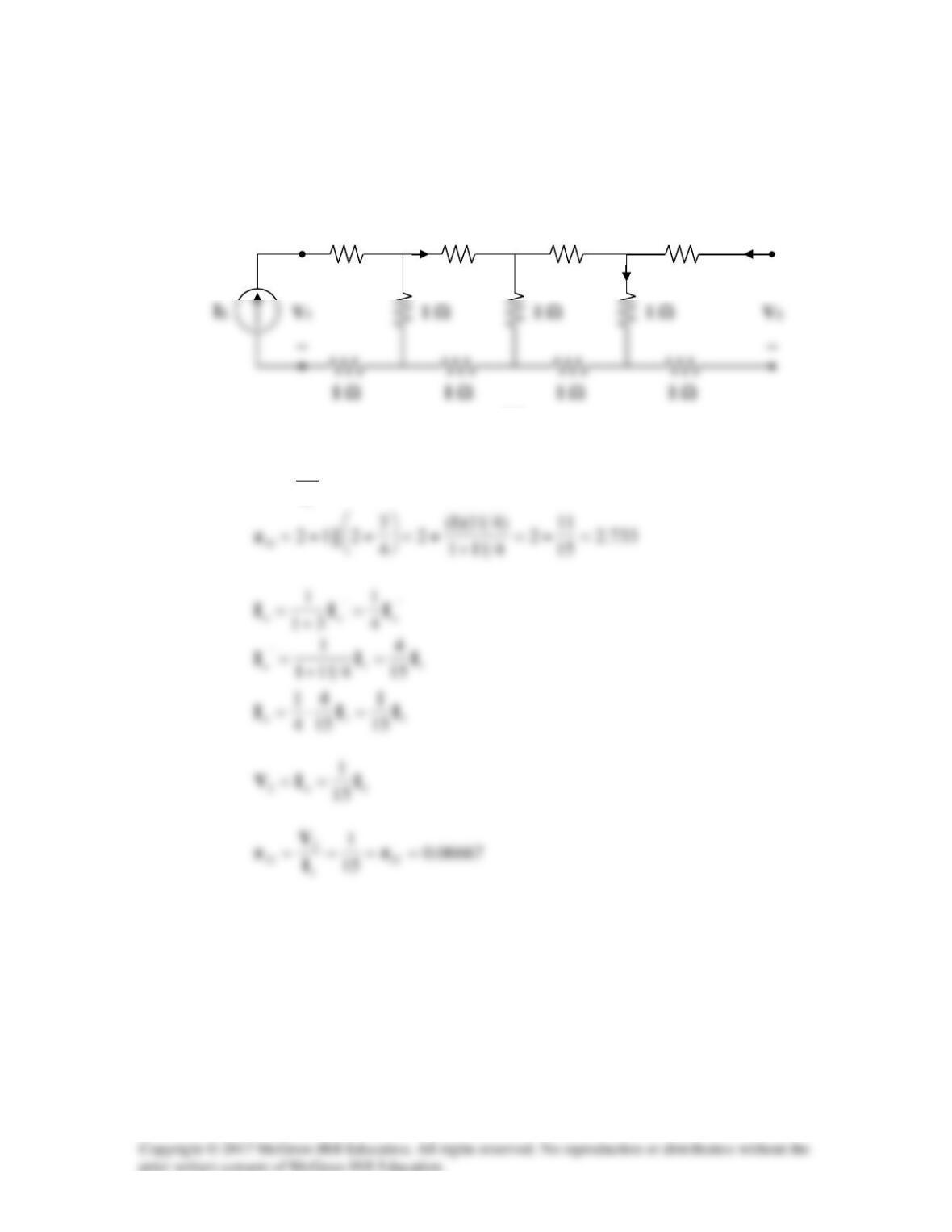
Transform the Π network to a T network.
5j12
120j
5j10j12
)10j)(12(
1+
=
−+
=Z
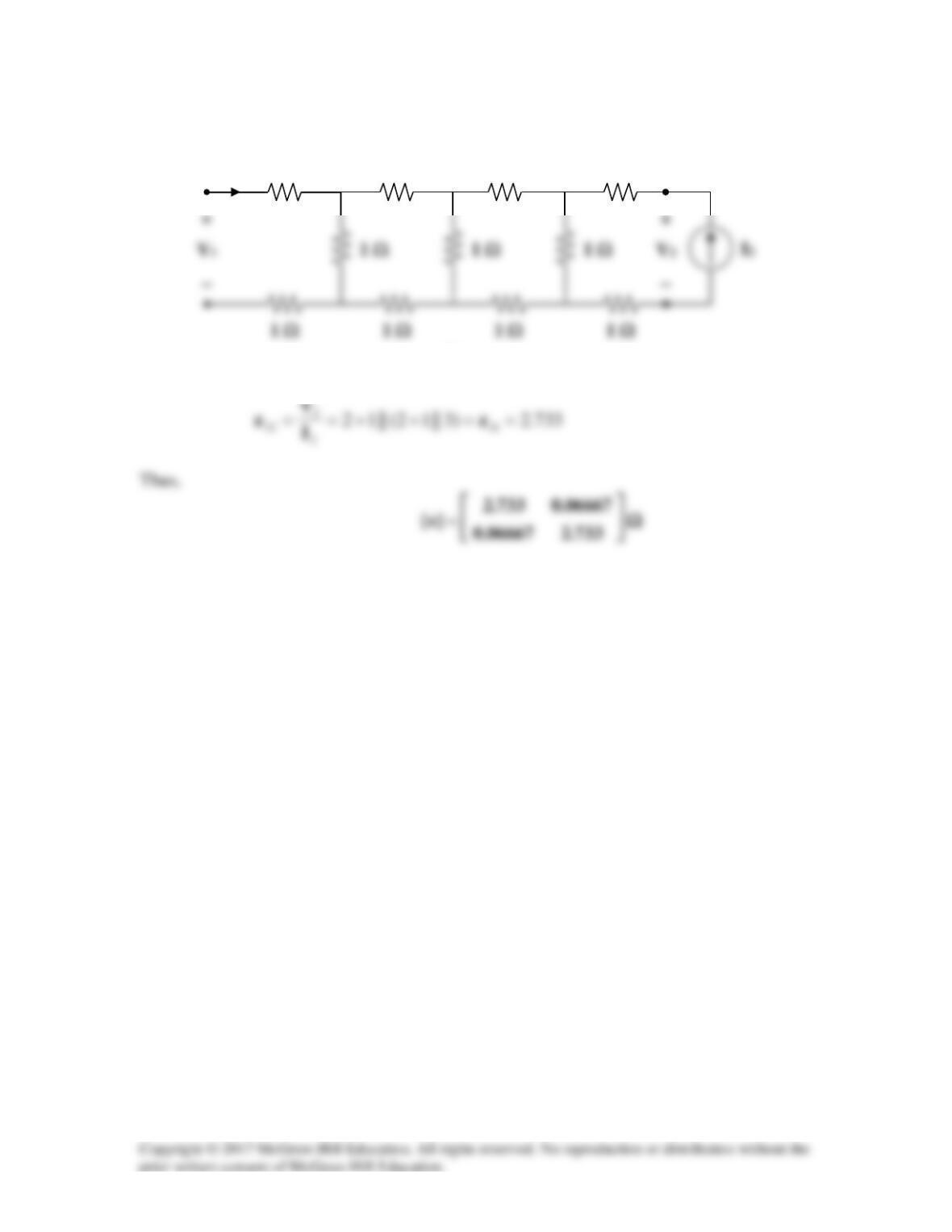
The z parameters are
Solution 19.5
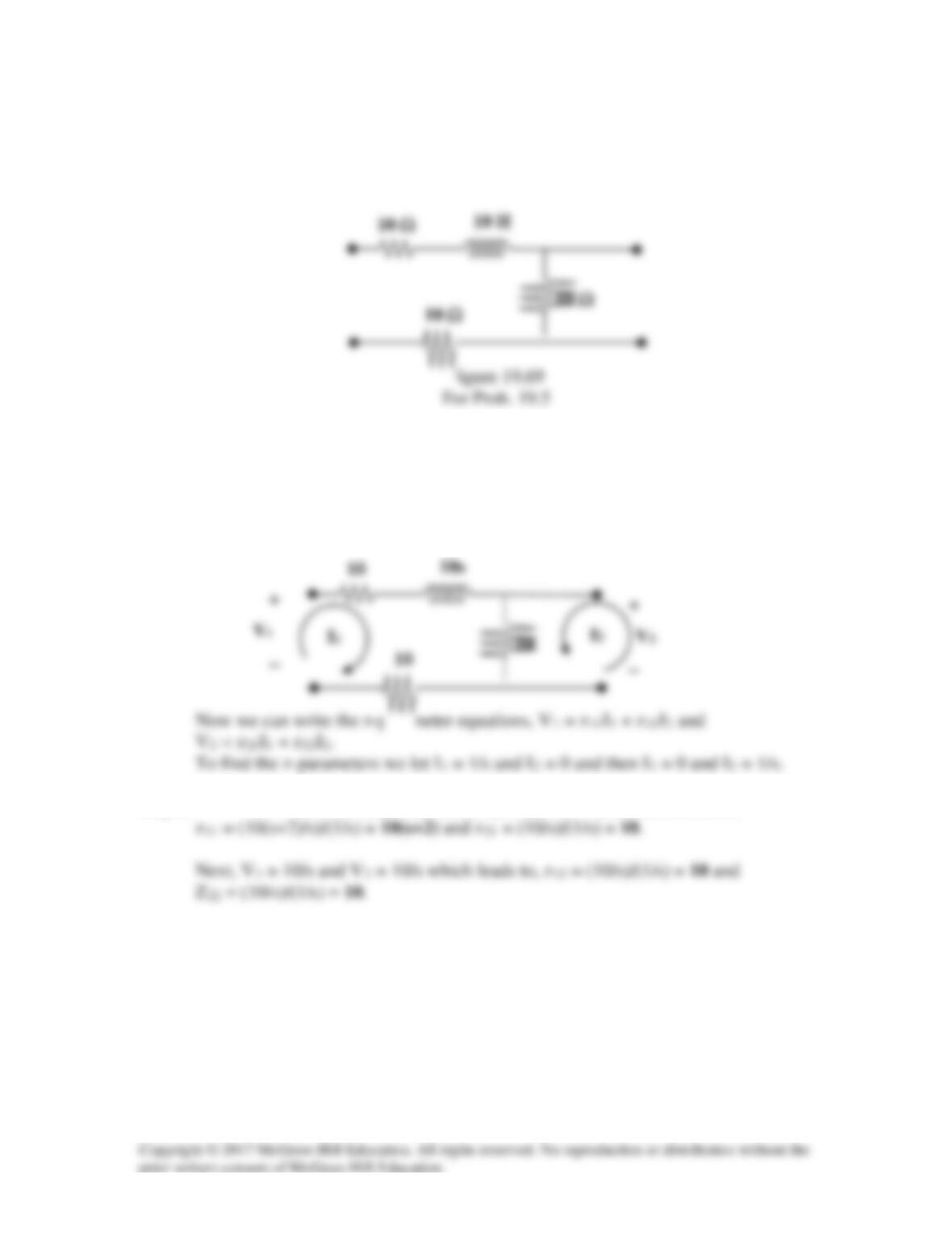
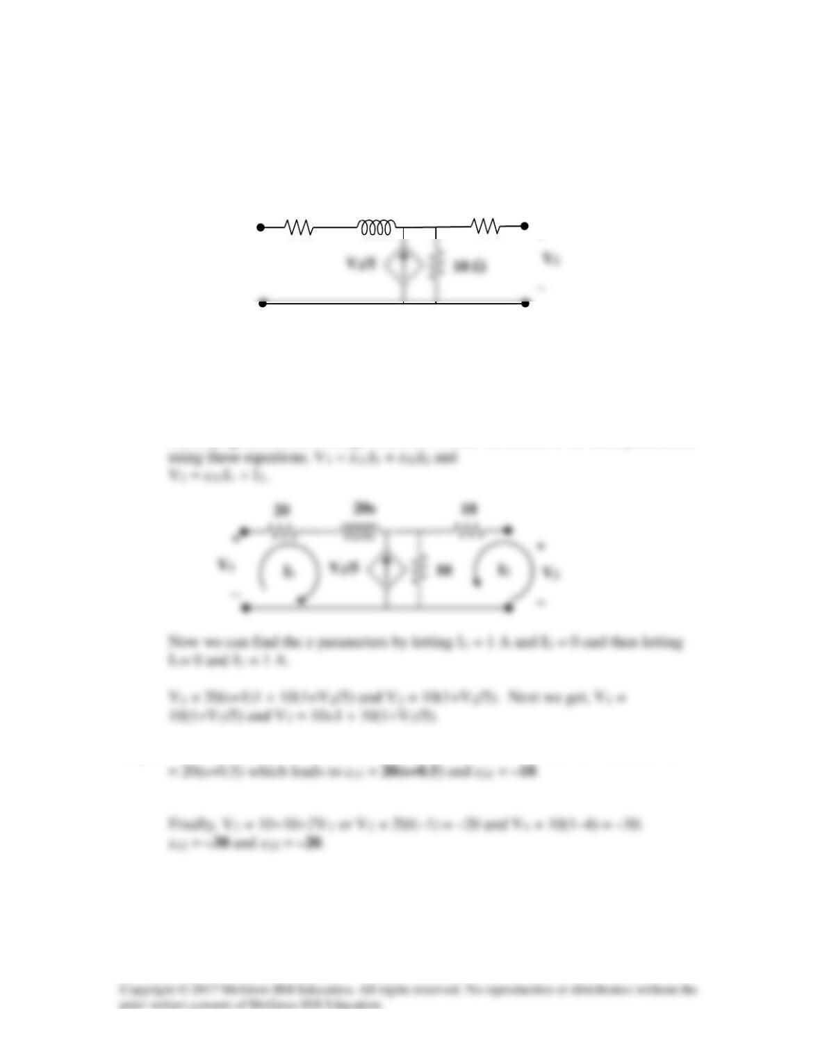
Obtain the z parameters for the network in Fig.19.69 as functions of s.
Solution
Step 1. We start by transforming the circuit into the s-domain and labeling the
currents and voltages so that we can use the mesh equations to solve for the z-
parameters.
Step 2. V1 = (10+10s+10)(1/s) = 10(s+2)/s and V2 = 10/s which leads to,
Solution 19.6
Compute the z parameters of the circuit in Fig. 19.70.
Figure 19.70
For Prob. 19.6 and 19.73.
Solution
Step 1. First we label the circuit so that we can find the z–parameters.
10 Ω
−
10 Ω
Solution 19.7
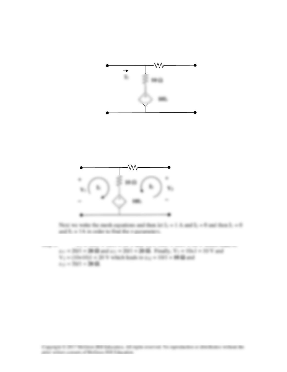
Calculate the impedance-parameter equivalent of the circuit in Fig. 19.71.
Figure 19.71
For Prob. 19.7.
Solution
Step 1. First we convert the circuit into the s-domain and then adding the
identifying current and voltage notations so that we can solve for the z parameters
Step 2. (1–2)V2 = 10 or V2 = –10 V and V1 = 20s + 20 + 10(1–2) = 20s+20–10
+
20 H
20 Ω
10 Ω
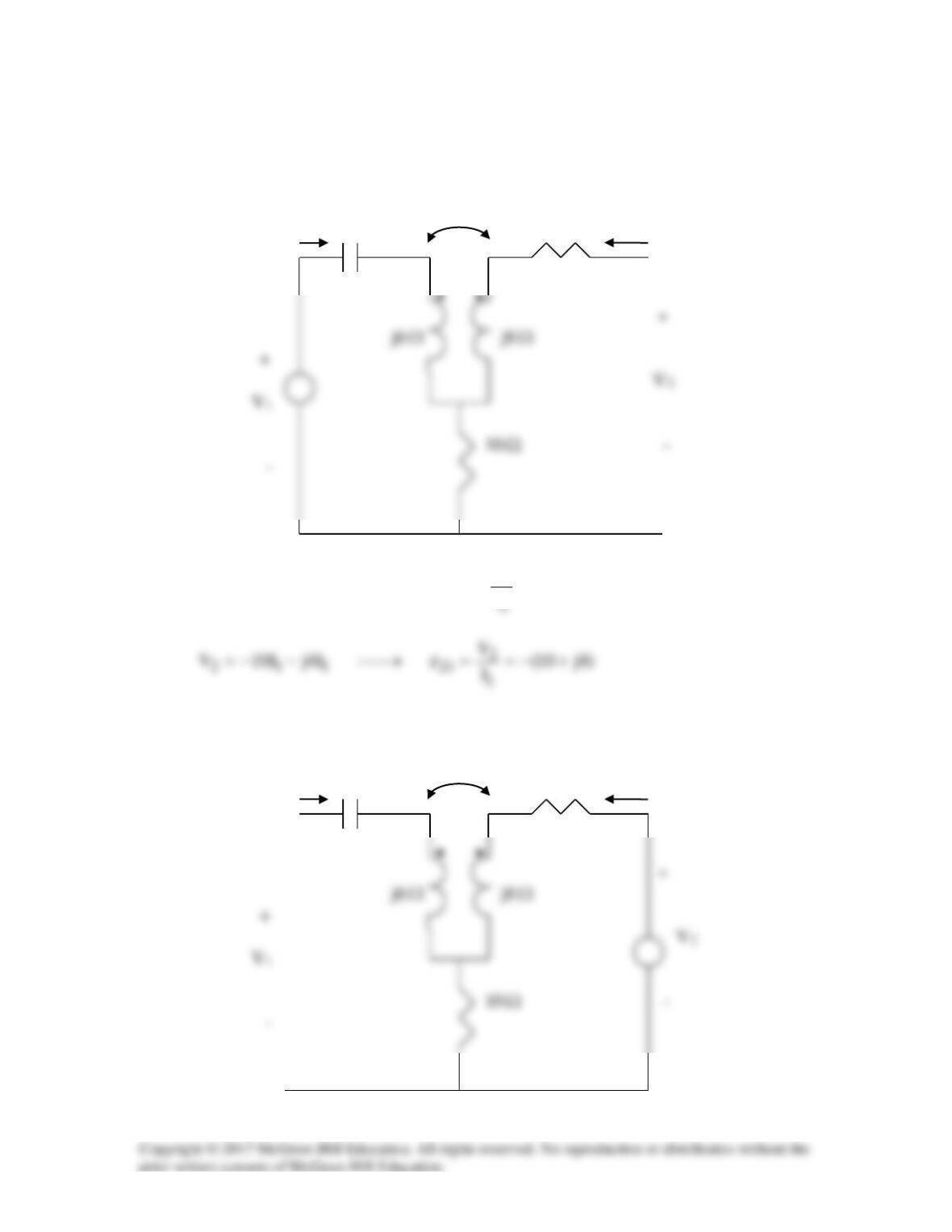
Solution 19.8
To get z11 and z21, consider the circuit below.
j4
Ω
I1 –j2
Ω
5
Ω
I2 =0
Ω
Ω
Ω
4j10
I
V
zI)6j2j10(V
1
1111
+==→+−=
To get z22 and z12, consider the circuit below.
j4
Ω
I1=0 –j2
Ω
5
Ω
I2
Ω
Ω
Ω
Thus,
Solution 19.9
16.02.02.04.05.0
21122211
=−=−=∆ xxyyyy
y
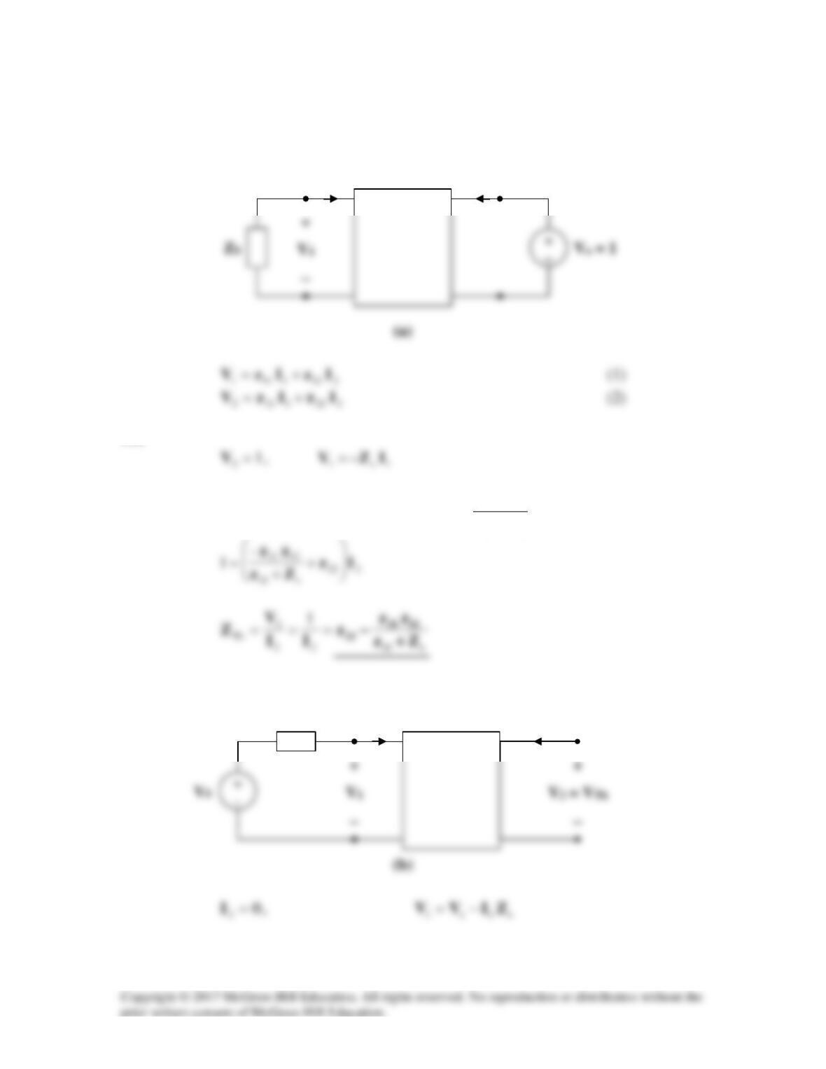
Solution 19.10
(a) This is a non-reciprocal circuit so that the two–port looks like the one shown in
Figs. (a) and (b).
(a)
−
−
I1
I2
(b) This is a reciprocal network and the two–port look like the one shown in Figs.
(c) and (d).
−
−
z11
z22
I1
I2
(b)
−
−
z11 – z12
z22 – z12
I1
I2
(d)
Solution 19.11
Solution 19.12
For the circuit shown in Fig. 19.73, let
10 6
[]
4 12
z−
= Ω
−
Find I1, I2, V1, and V2.
2Ω I1 I2
+
+
7.5 A 4Ω V1 10 Ω
V2
– –
Figure 19.73
For Prob. 19.12.
Solution
1 12
10 6V II= −
(1)
If we convert the current source to a voltage source, that portion of the circuit becomes
what is shown below. Now we write an mesh equation.
4Ω 2 Ω I1
Substituting (3) and (4) into (1) and (2), we get
[z]
Solution 19.13
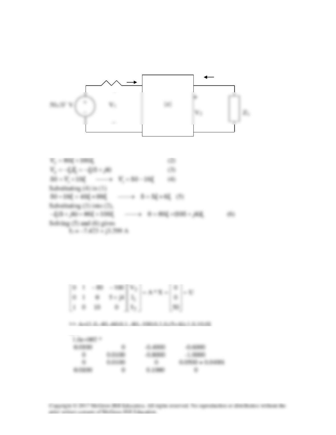
Consider the circuit as shown below.
10 Ω I1 I2
+
–
1 12
40 60VII= +
(1)
We can check the answer using MATLAB.
First we need to rewrite equations 1-4 as follows,
0
V
604001
1
−−
>> A=[1,0,-40,-60;0,1,-80,-100;0,1,0,(5+4i);1,0,10,0]
A =
U =
0
0
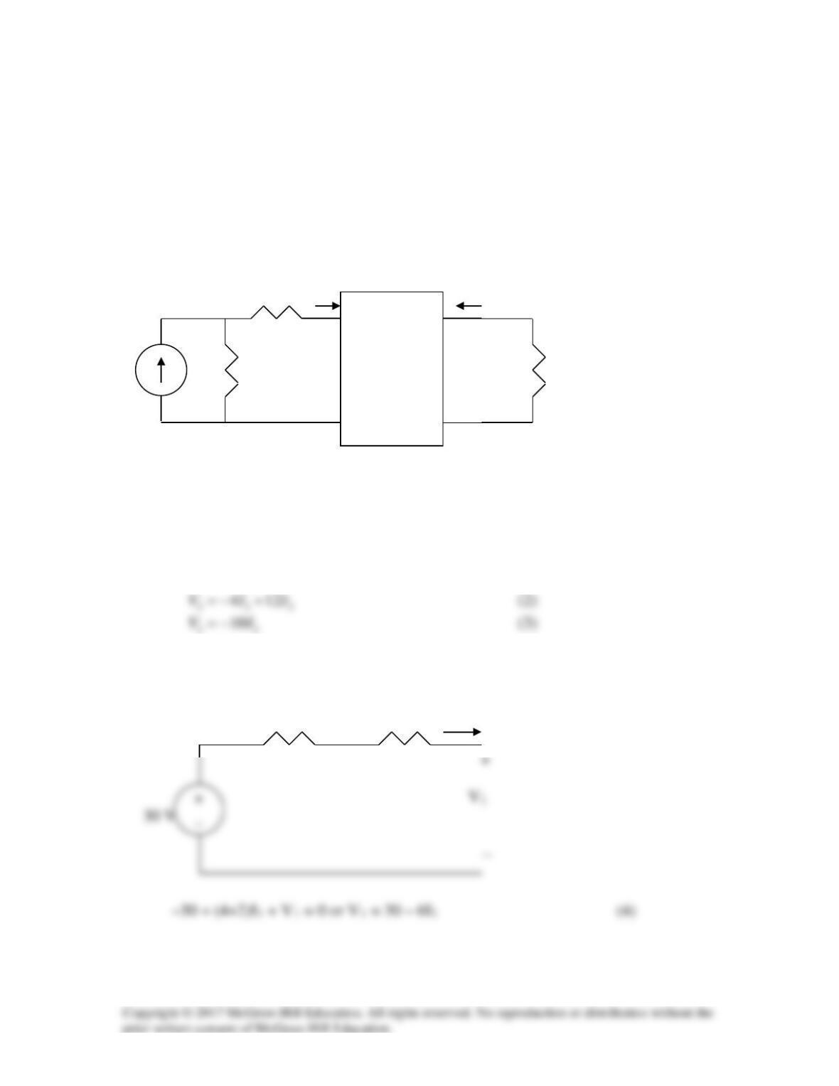
Solution 19.14
To find
Th
Z
, consider the circuit in Fig. (a).
But
Hence,
2
s11
12
12121s11
–
)(0 I
Zz
z
IIzIZz +
=→++=
To find
Th
V
, consider the circuit in Fig. (b).
I1
I2
I1
ZS
I2 = 0