Solution 13.77
(a) This is a single phase transformer. V1 = 13.2 kV, V2 = 120 V
(b) P = VI or I = P/V = 100/120 = 0.8333 A
Solution 13.78
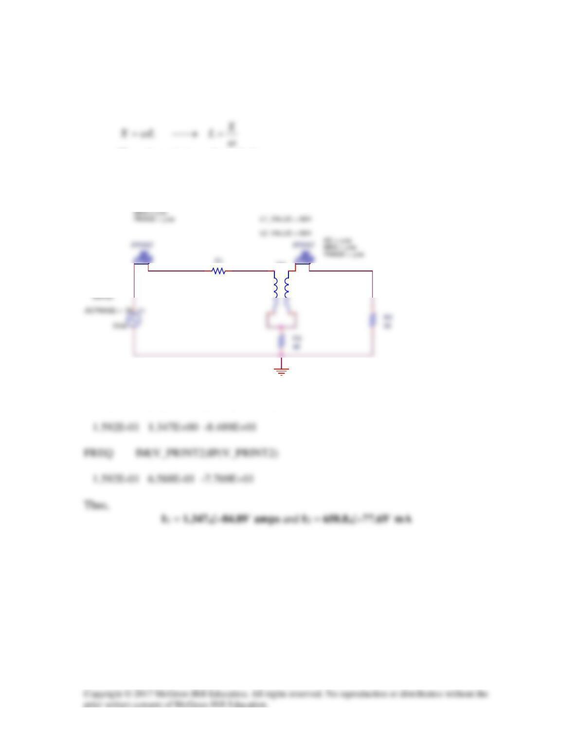
We convert the reactances to their inductive values.
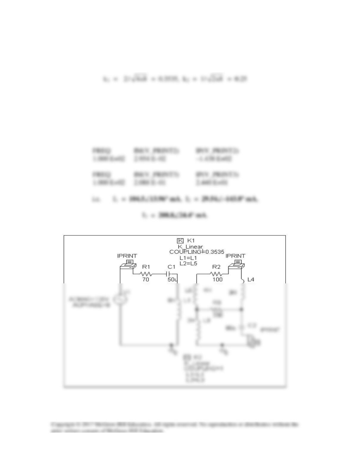
The schematic is as shown below.
FREQ IM(V_PRINT1)IP(V_PRINT1)
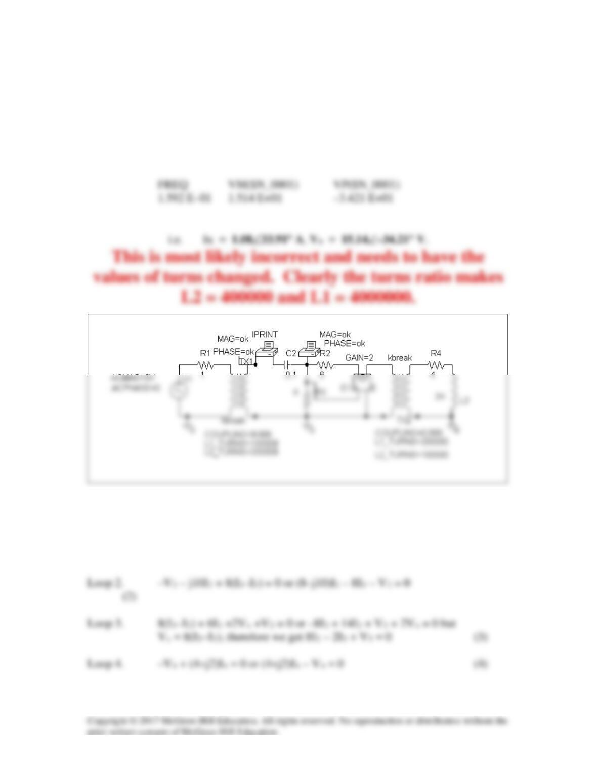
TX1
COUPLING = 0.5
R1
20
0
AC = y es
Solution 13.79
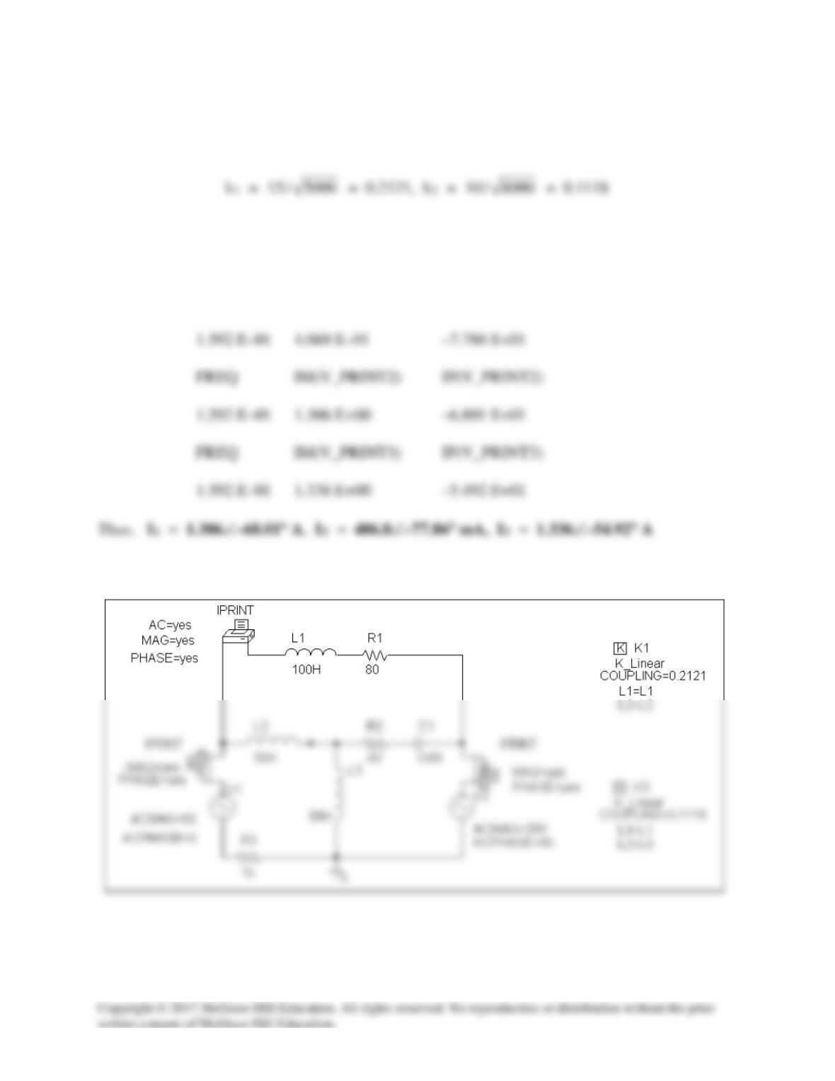
The schematic is shown below.
In the AC Sweep box, we type Total Pts = 1, Start Freq = 0.1592, and End Freq = 0.1592.
After the circuit is saved and simulated, the output includes
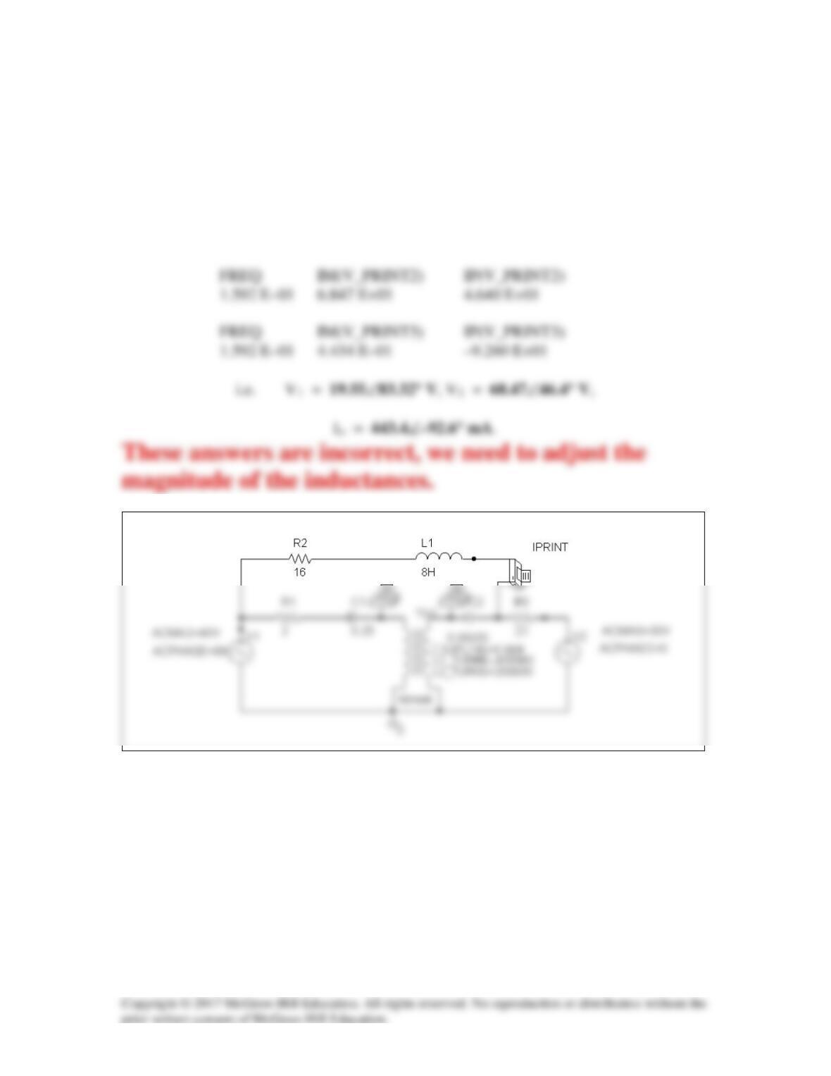
FREQ IM(V_PRINT1) IP(V_PRINT1)
Solution 13.80
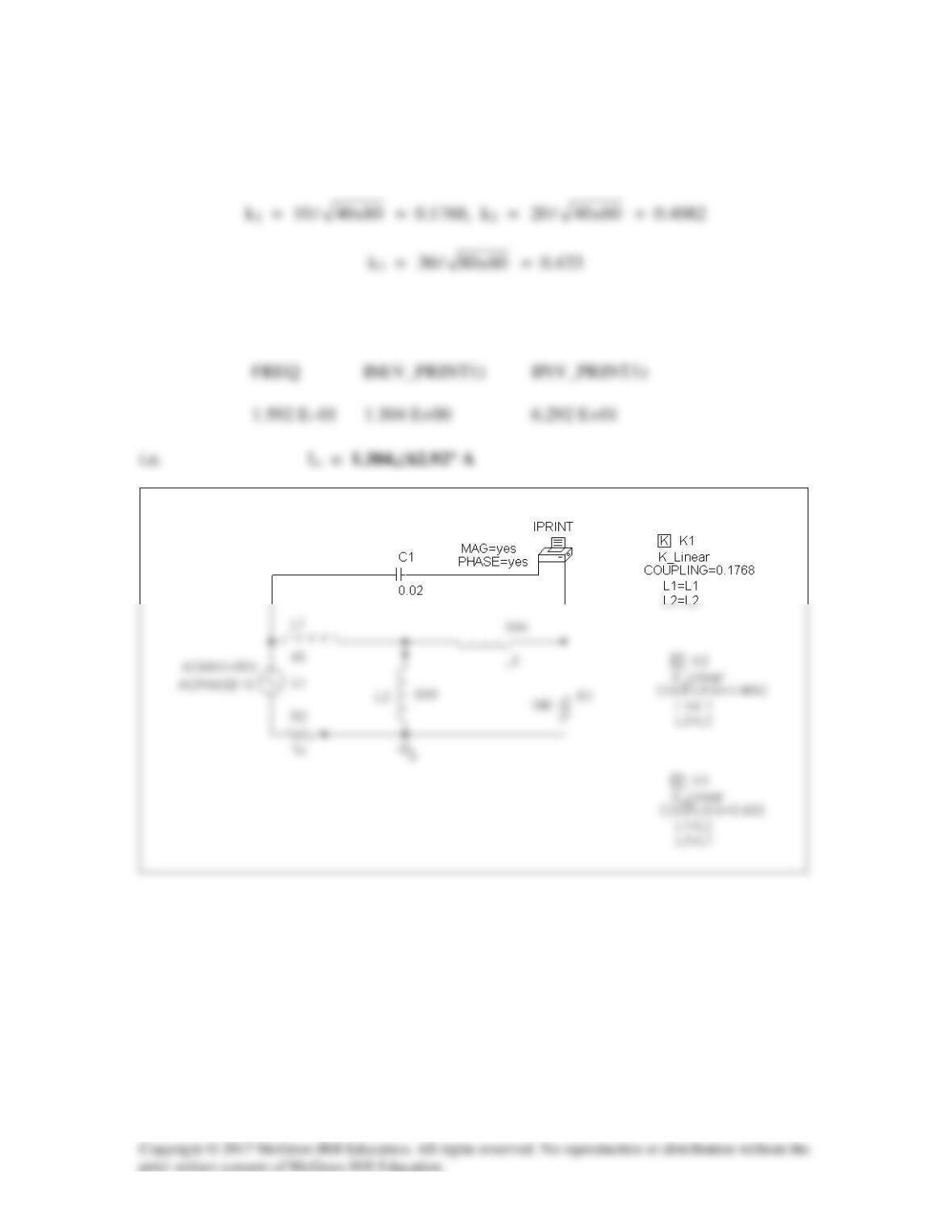
The schematic is shown below.
In the AC Sweep box, we set Total Pts = 1, Start Freq = 0.1592, and
End Freq = 0.1592. After the simulation, we obtain the output file which includes
Solution 13.81
The schematic is shown below.
In the AC Sweep box, we let Total Pts = 1, Start Freq = 100, and End Freq = 100.
After simulation, the output file includes
FREQ IM(V_PRINT1) IP(V_PRINT1)
1.000 E+02 1.0448 E–01 1.396 E+01
Solution 13.82
The schematic is shown below. In the AC Sweep box, we type Total Pts = 1,
Start Freq = 0.1592, and End Freq = 0.1592. After simulation, we obtain the output
file which includes
FREQ IM(V_PRINT1) IP(V_PRINT1)
1.592 E–01 1.955 E+01 8.332 E+01
Solution 13.83
The schematic is shown below. In the AC Sweep box, we set Total Pts = 1,
Start Freq = 0.1592, and End Freq = 0.1592. After simulation, the output file includes
FREQ IM(V_PRINT1) IP(V_PRINT1)
1.592 E–01 1.080 E+00 3.391 E+01
Checking with hand calculations.
Loop 1. –6 + 1I1 + V1 = 0 or I1 + V1 = 6 (1)
We also need the constraint equations, V2 = 2V1, I1 = 2I2, V3 = 2V4, and I4 = 2I3.
We can eliminate the voltages from the equations (we only need I2 and I3 to obtain the
required answers) by,
Next we use I1 = 2I2 and I4 = 2I3 to end up with the following equations,
This leads to (6–j5)(–1.75–j)I3 – 4I3 = (–10.5–5–4+j(8.75–6))I3 = (–19.5+j2.75)I3 = 6
or
I3 = 6/(19.69296∠171.973°) = 0.304677∠–171.973° amps
Therefore,
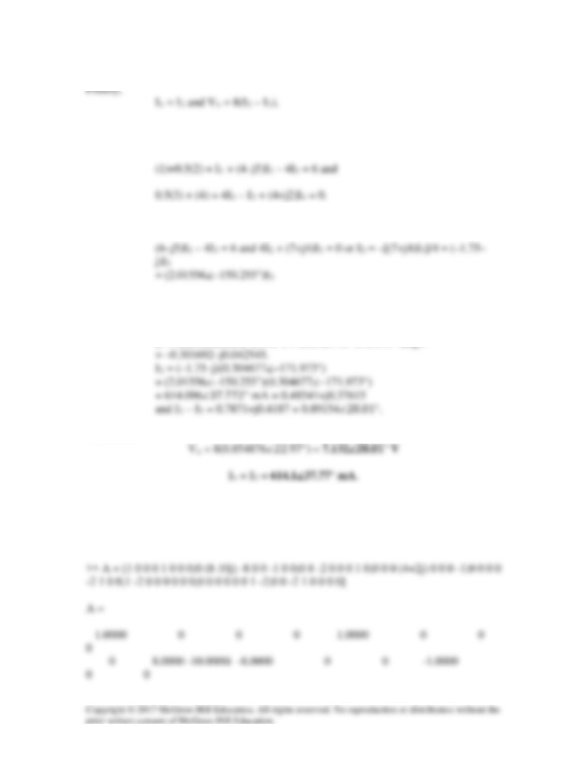
Checking with MATLAB we get A and X from equations (1) – (4) and the four constraint
equations.
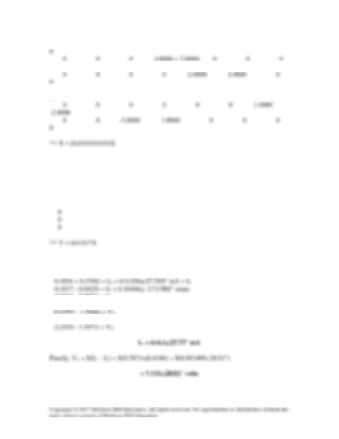
0 8.0000 -2.0000 0 0 0 1.0000
-1.0000
1.0000 -2.0000 0 0 0 0 0
0
X =
6
0
0
0
0
Y =
0.9708 + 0.7523i = I1 = 1.2817∠37.773° amps
-0.6034 – 0.0851i = I4
5.0292 – 0.7523i = V1
-4.4867 – 3.0943i = V3
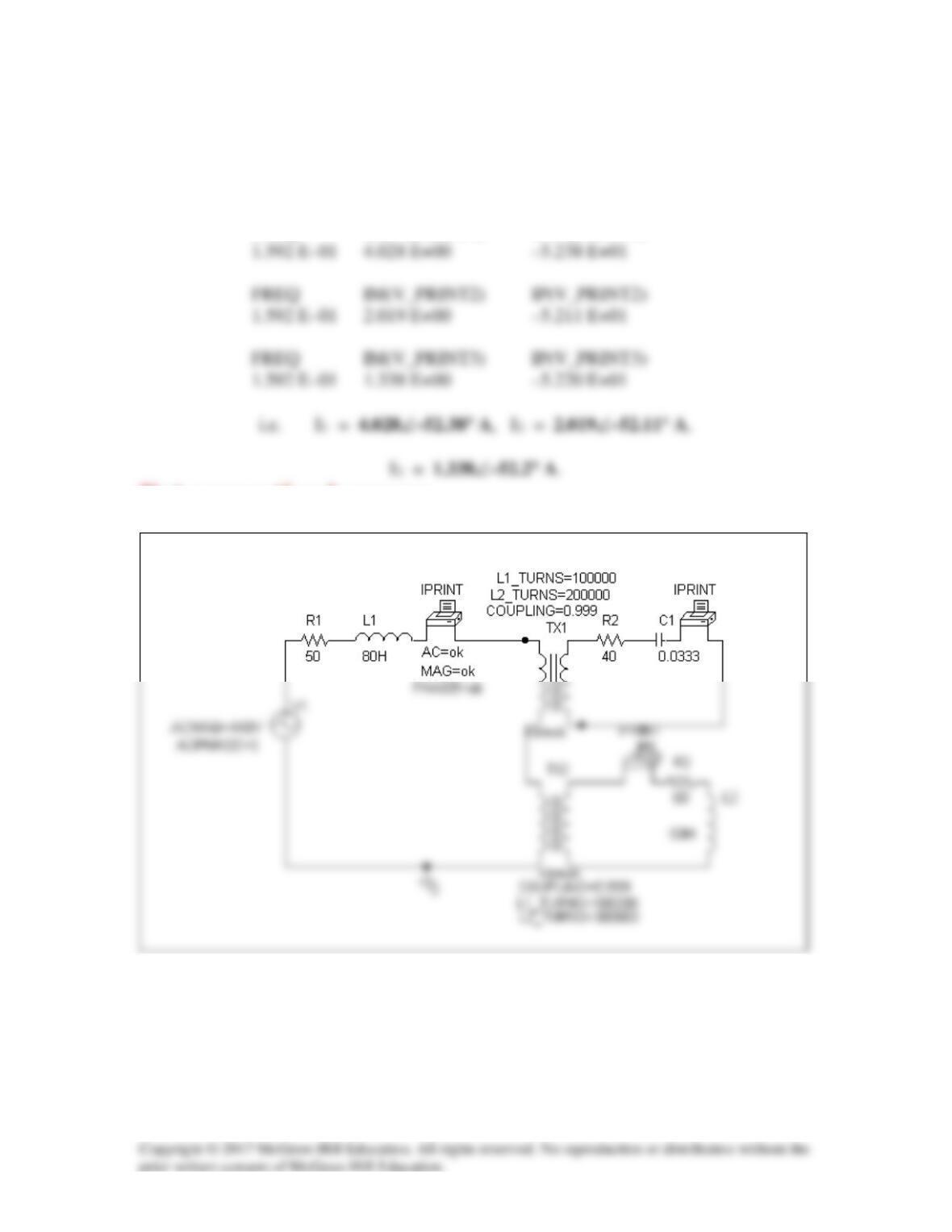
Solution 13.84
The schematic is shown below. we set Total Pts = 1, Start Freq = 0.1592, and End
Freq = 0.1592. After simulation, the output file includes
FREQ IM(V_PRINT1) IP(V_PRINT1)
Dot convention is wrong.
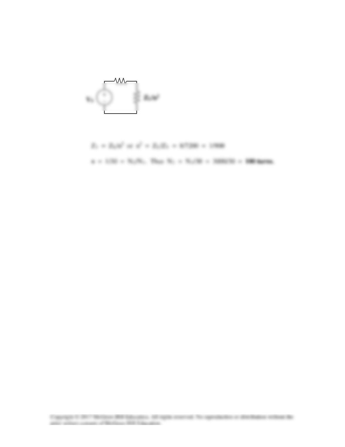
Solution 13.85
For maximum power transfer,
Z1
Solution 13.86