Thus,
v(t) = Ldi/dt = [1.323(–Asin1.323t + Bcos1.323t)e–0.5t] +
Solution 8.46
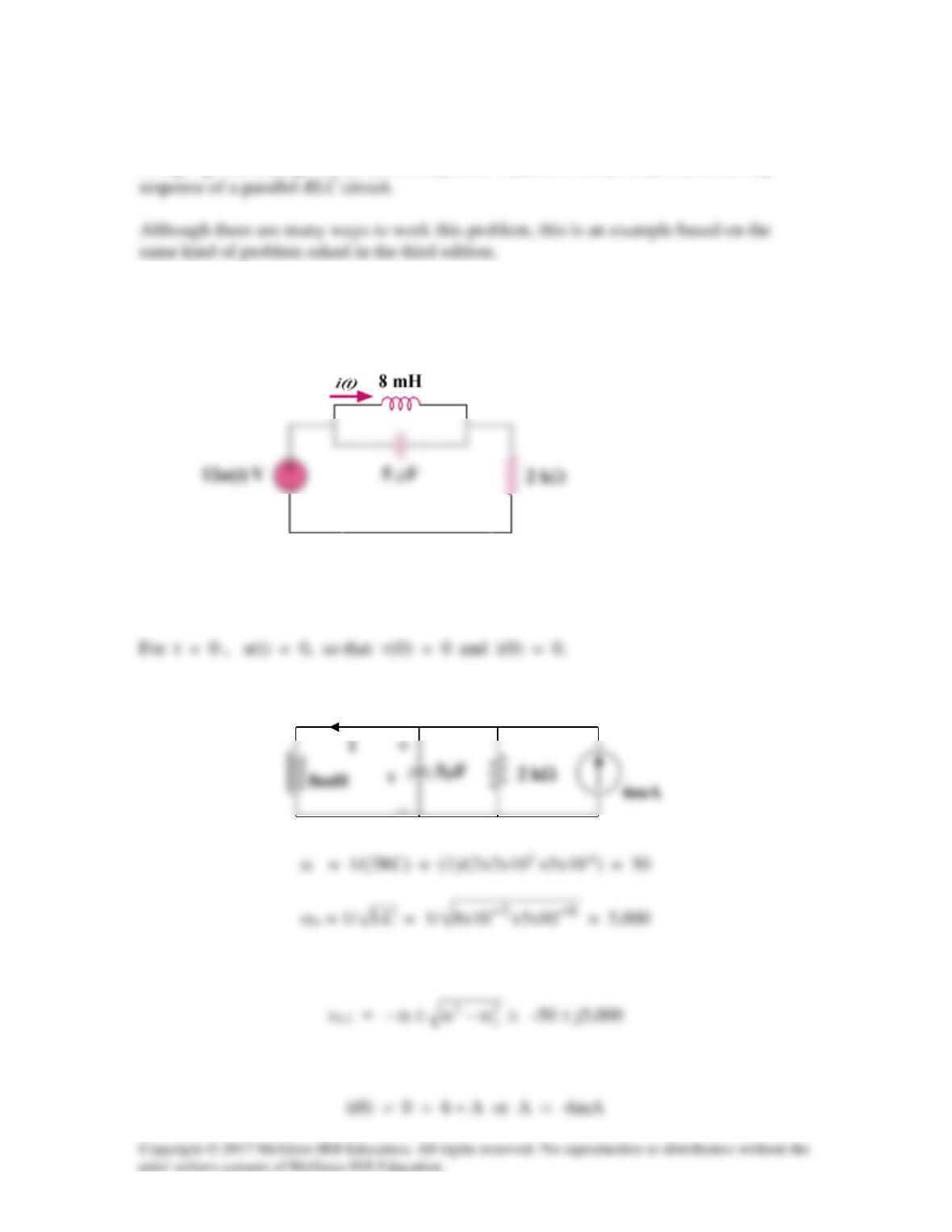
Using Fig. 8.93, design a problem to help other students to better understand the step
Problem
Find i(t) for t > 0 in the circuit in Fig. 8.93.
Figure 8.93
Solution
For t > 0, we have a parallel RLC circuit with a step input, as shown below.
Since α < ωo, we have an underdamped response.
Thus, i(t) = Is + [(Acos5,000t + Bsin5,000t)e–50t], Is = 6mA
−
Solution 8.47
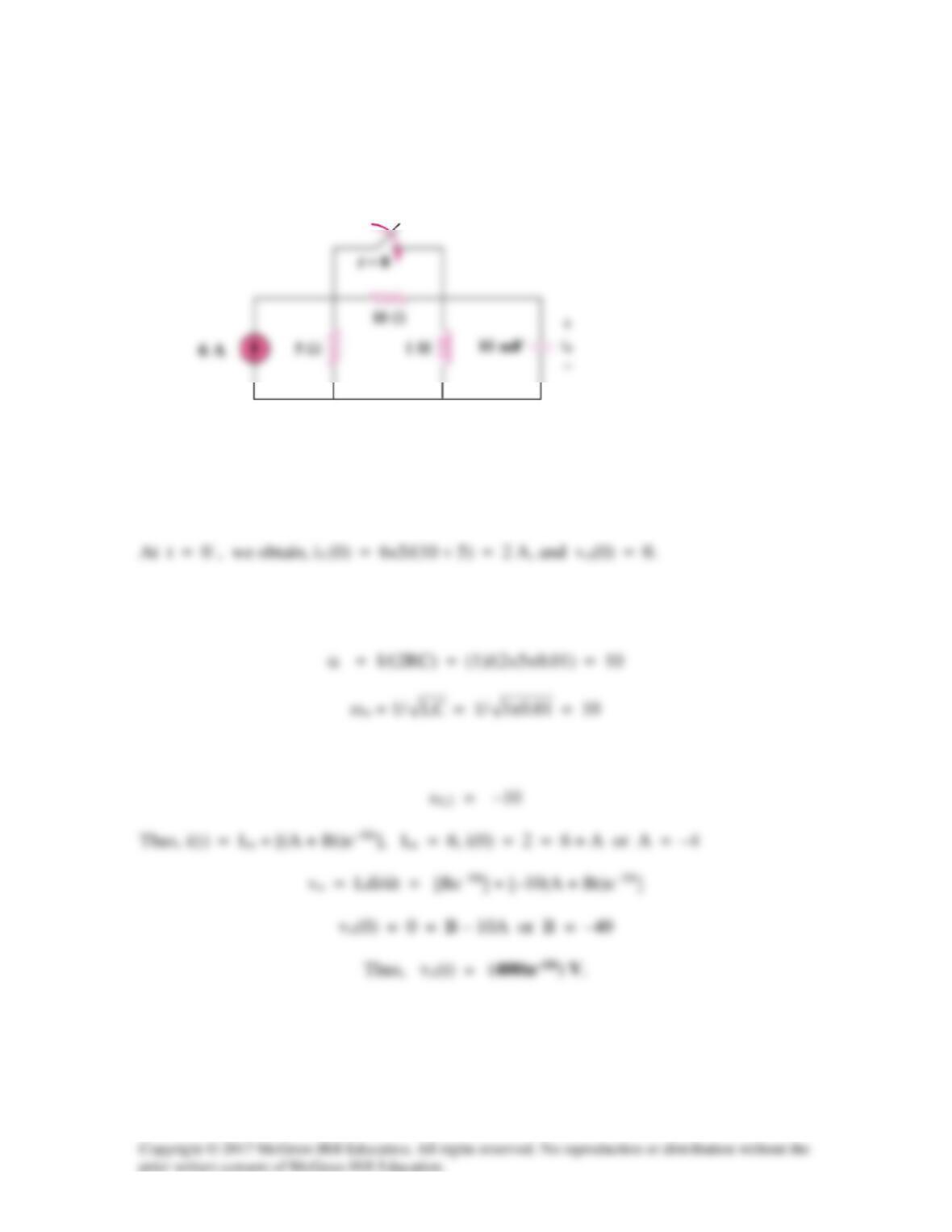
Find the output voltage vo(t) in the circuit of Fig. 8.94.
Figure 8.94
For Prob. 8.47.
Solution
For t > 0, the 10-ohm resistor is short-circuited and we have a parallel RLC circuit with
a step input.
Since α = ωo, we have a critically damped response.
Solution 8.48
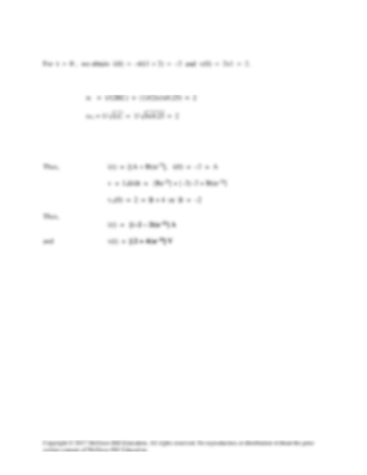
For t > 0, the voltage is short-circuited and we have a source–free parallel RLC circuit.
Since α = ωo, we have a critically damped response.
s1,2 = –2
Solution 8.49
Determine i(t) for t > 0 in the circuit of Fig. 8.96.
Figure 8.96
For Prob. 8.49.
Solution
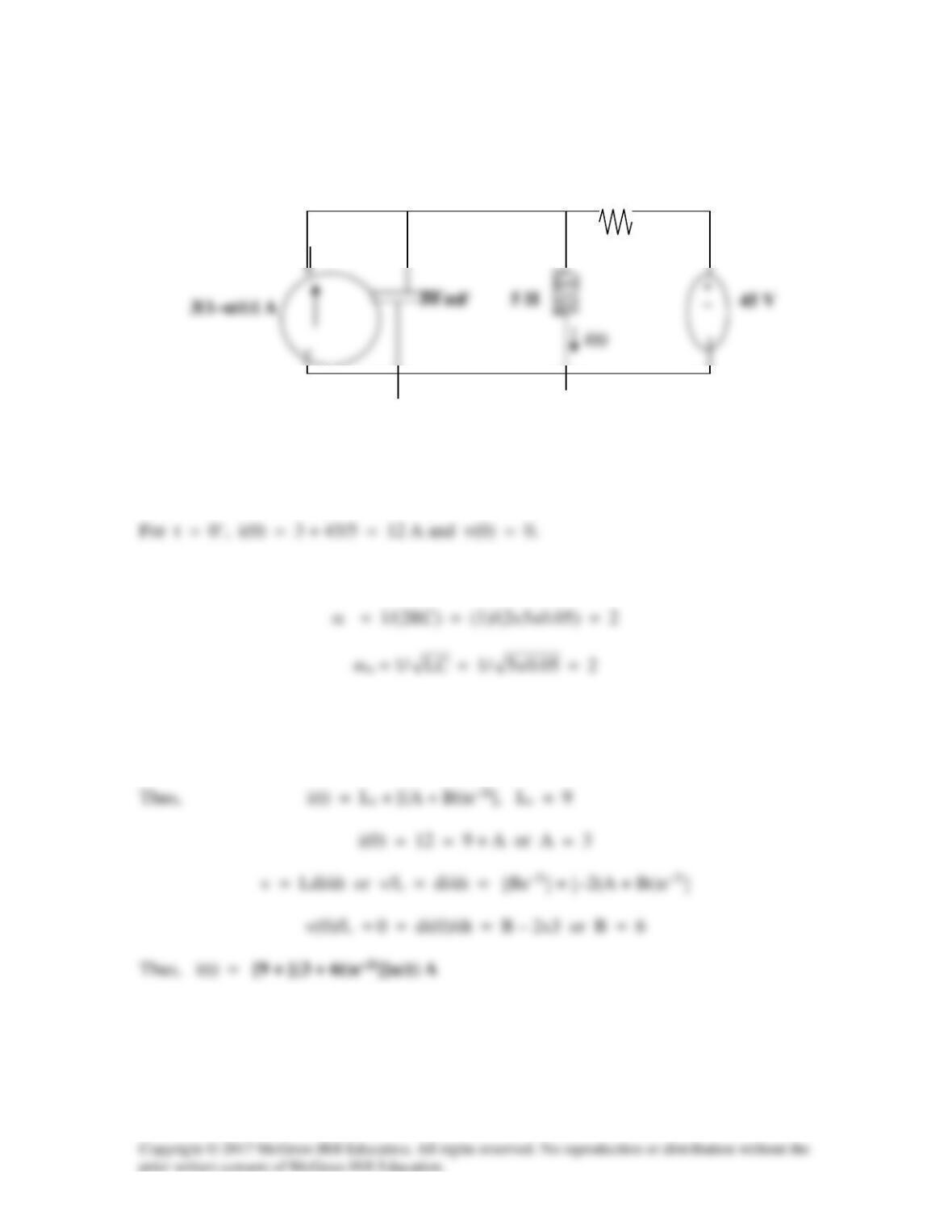
For t > 0, we have a parallel RLC circuit with a step change in the input.
Since α = ωo, we have a critically damped response.
s1,2 = –2
5
Ω
Solution 8.50
For the circuit in Fig. 8.97, find i(t) for t > 0.
Figure 8.97
For Prob. 8.50.
Solution
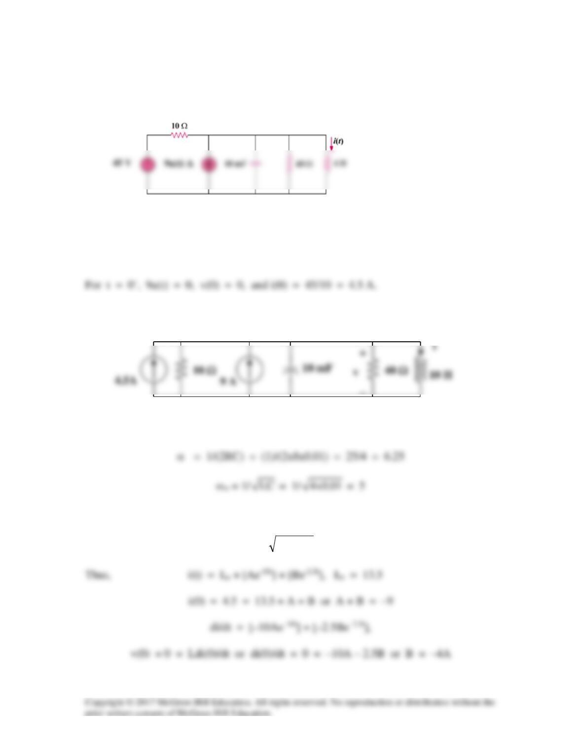
For t > 0, we have a parallel RLC circuit.
Iss = 4.5 + 9 = 13.5 A and R = 10||40 = 8 ohms
Since α > ωo, we have a overdamped response.
s1,2 =
=ω−α±α− 2
o
2
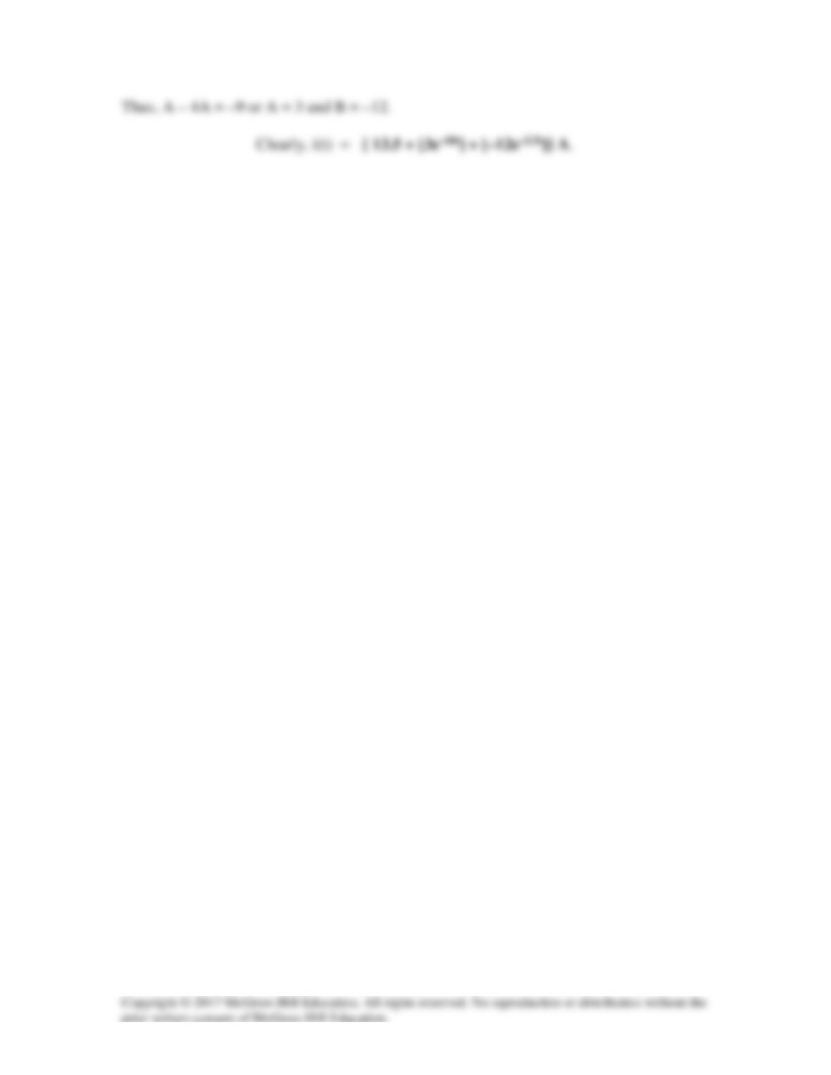
–10, –2.5
−
Solution 8.51
Let i = inductor current and v = capacitor voltage.
For t > 0, we have a parallel, source–free LC circuit (R = ∞).
α = 1/(2RC) = 0 and ωo = 1/
LC
which leads to s1,2 = ± jωo
Solution 8.52
The step response of a parallel RLC circuit is
Solution
RC2
1
300 ==
α
(1)
Solution 8.53
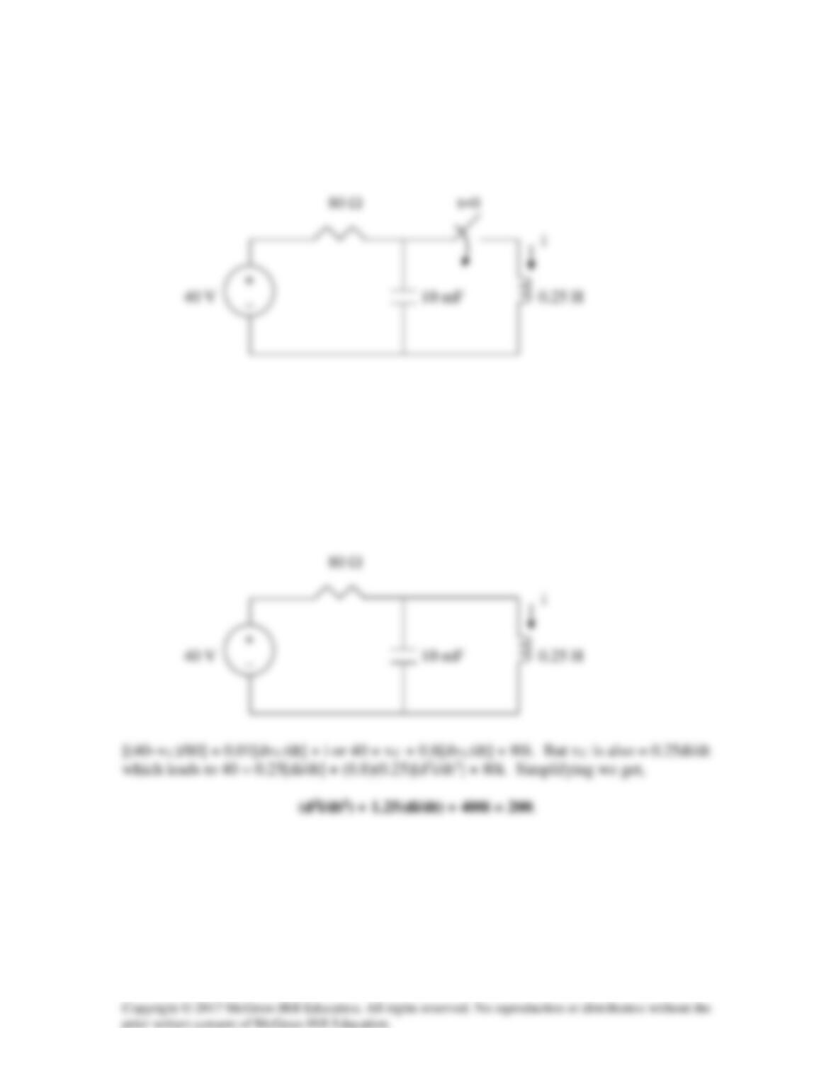
After being open for a day, the switch in the circuit of Fig. 8.99 is closed at t=0. Find the
differential equation describing i(t), t >0.
Figure 8.99
For Prob. 8.53.
Solution
For t < 0, i(0) = 0 and vC(0) = 40.
For t > 0, we have the circuit as shown below.
Solution 8.54
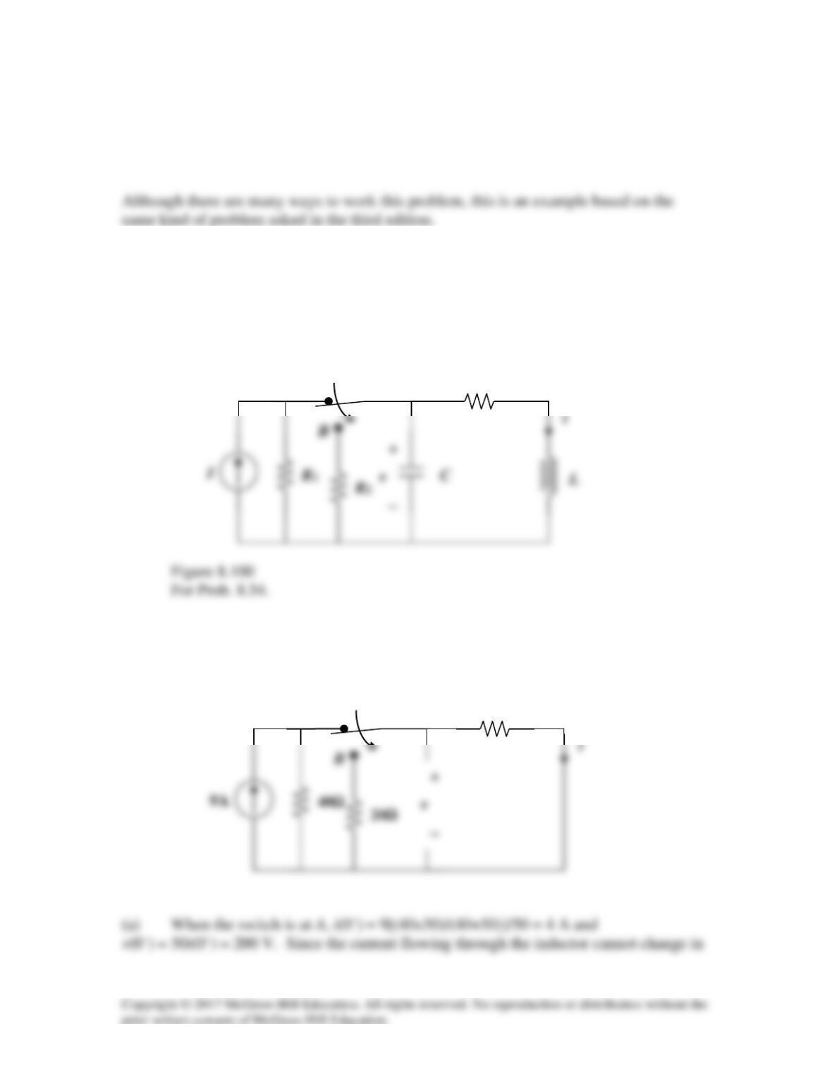
Using Fig. 8.100, design a problem to help other students better understand general
second–order circuits.
Problem
For the circuit in Fig. 8.100, let I = 9A, R1 = 40 Ω, R2 = 20 Ω, C = 10 mF, R3 = 50 Ω,
and L = 20 mH. Determine: (a) i(0+) and v(0+), (b) di(0+)/dt and dv(0+)/dt, (c) i(∞) and
v(∞).
i
L
C
B
Solution
(a) When the switch is at A, the circuit has reached steady state. Under this condition,
the circuit is as shown below.
B
i
t = 0
R3
A
t = 0
A
50Ω
(b) For the inductor, vL = L(di/dt) or di(0+)/dt = vL(0+)/0.02.
For the capacitor, iC = C(dv/dt) or dv(0+)/dt = iC(0+)/0.01.
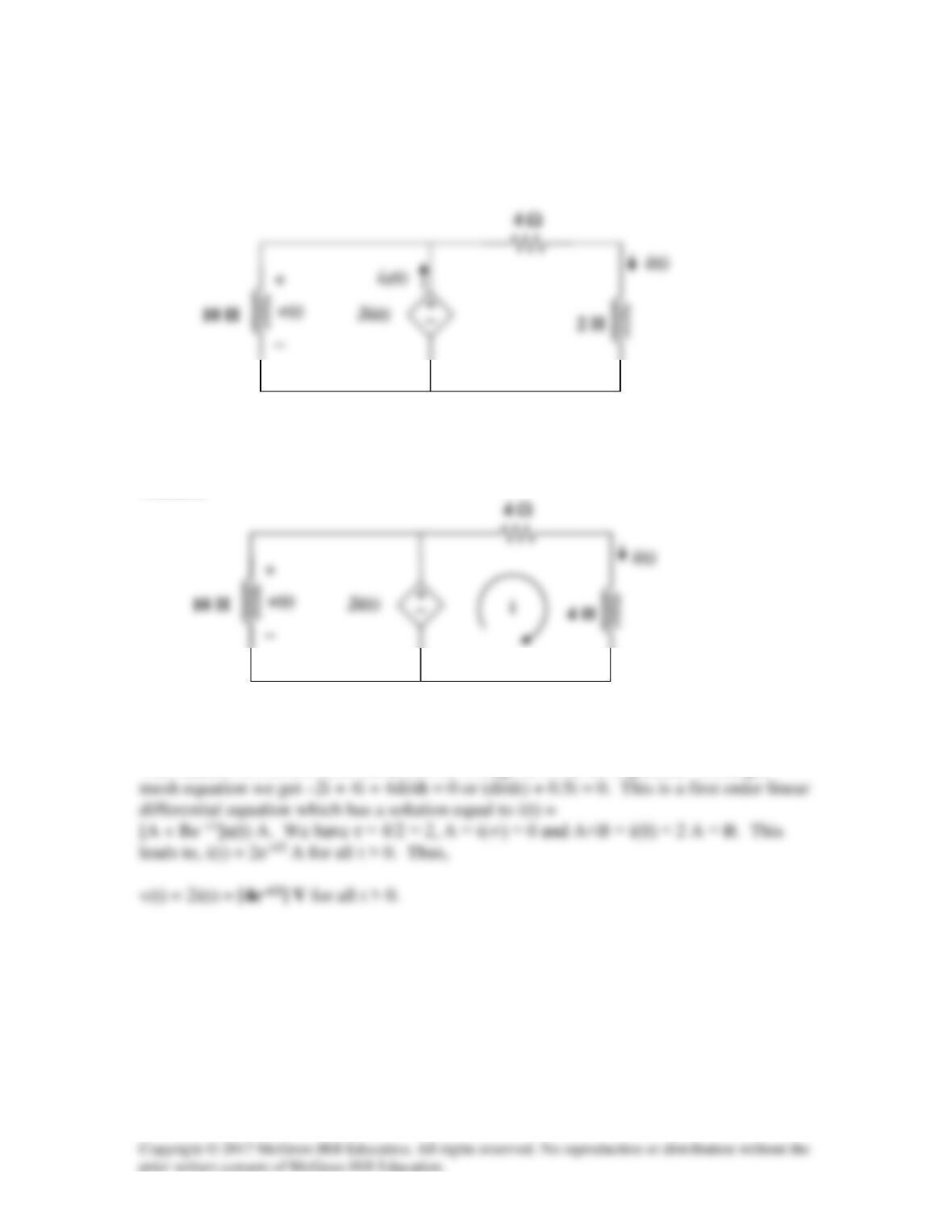
(c) When the switch is in position B, the circuit reaches steady state. Since it is
source-free, i and v decay to zero with time.
Solution 8.55
For the circuit in Fig. 8.101, find v(t) for t > 0. Assume that i(0+) = 2 A.
Figure 8.101
For Prob. 8.55.
Solution
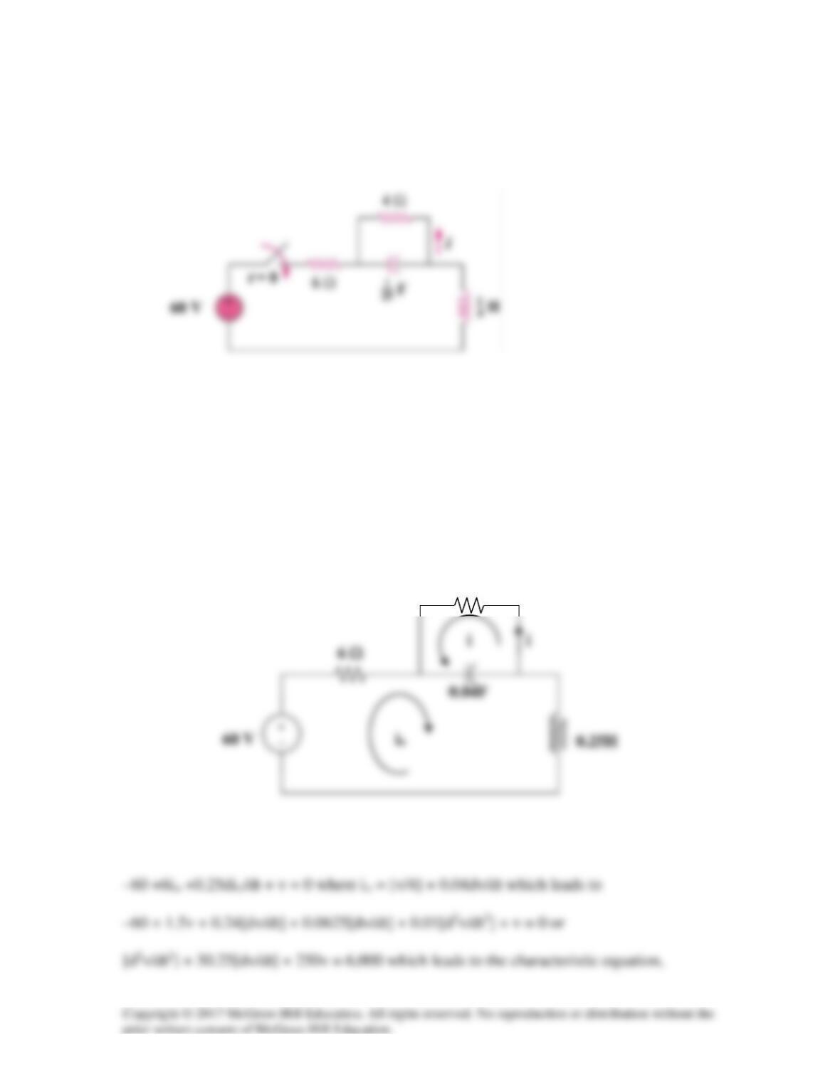
We find that i1 = v(t) = 2i(t).
The inductor on the left does not affect the voltage so it can be neglected. Writing a
Solution 8.56
In the circuit of Fig. 8.102, find i(t) for t > 0.
Figure 8.102
For Prob. 8.56.
Solution
For t < 0, i(0) = 0 and v(0) = 0.
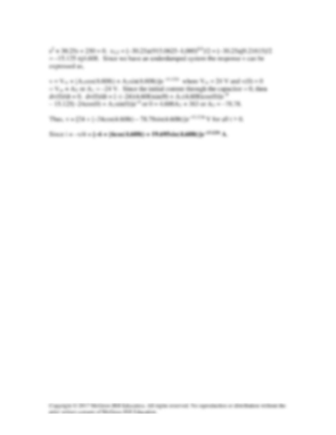
For t > 0, the circuit is as shown below.
6 Ω
Applying KVL to the larger loop and letting v = the capacitor voltage positive on the left,
4 Ω
Solution 8.57
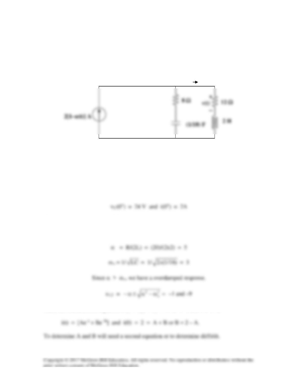
Given the circuit shown in Fig. 8.103, determine the characteristic equation of the circuit
and the values for i(t) and v(t) for all t > 0.
Figure 8.103
For Prob. 8.57.
Solution
Let vC = capacitor voltage (plus on top and negative on the bottom) and i = inductor
current. At t = 0+, the circuit has reached steady–state and the current source goes to zero.
We now have a source-free RLC circuit.
R = 8 + 12 = 20 ohms, L = 2 H, C = (1/18) F.
Thus, the characteristic equation is (s + 1)(s + 9) = 0 or s2 + 10s + 9 = 0.
i(t)
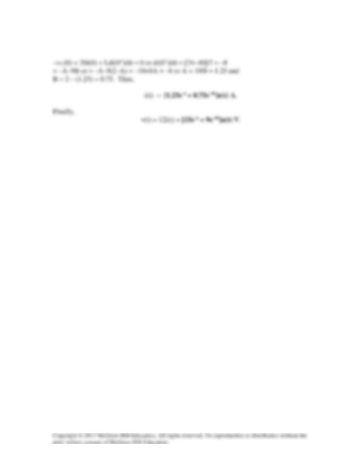
We only need to evaluate the loop equation at t = 0+ or
Solution 8.58
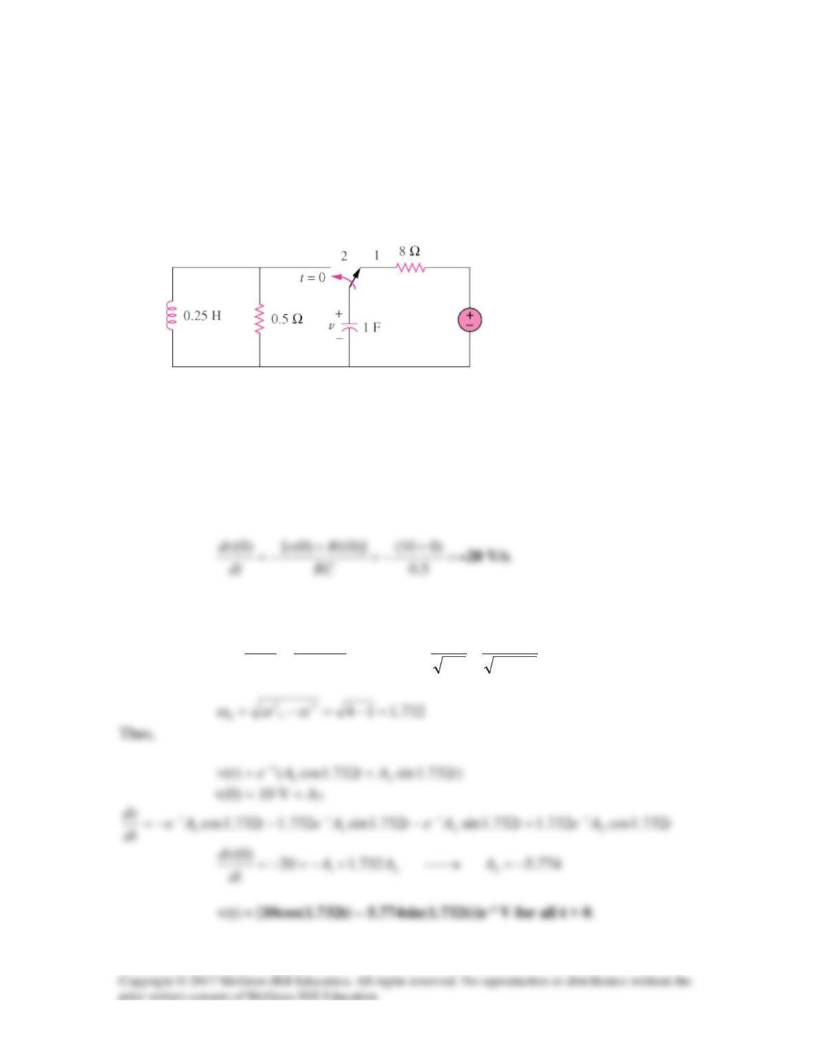
In the circuit of Fig. 8.104, the switch has been in position 1 for a long time but moved to
position 2 at t = 0. Find:
(a) v(0+), dv(0+)/dt
(b) v(t) for t ≥ 0.
Figure 8.104
For Prob. 8.58.
Solution
(a) Let i =inductor current, v = capacitor voltage i(0) =0, v(0+) = 10 V.
(b) For
0≥t
, the circuit is a source-free RLC parallel circuit.
2
125.0
11
,1
15.02
1
2
1====== xLC
xxRC
o
ωα
10 V
Solution 8.59
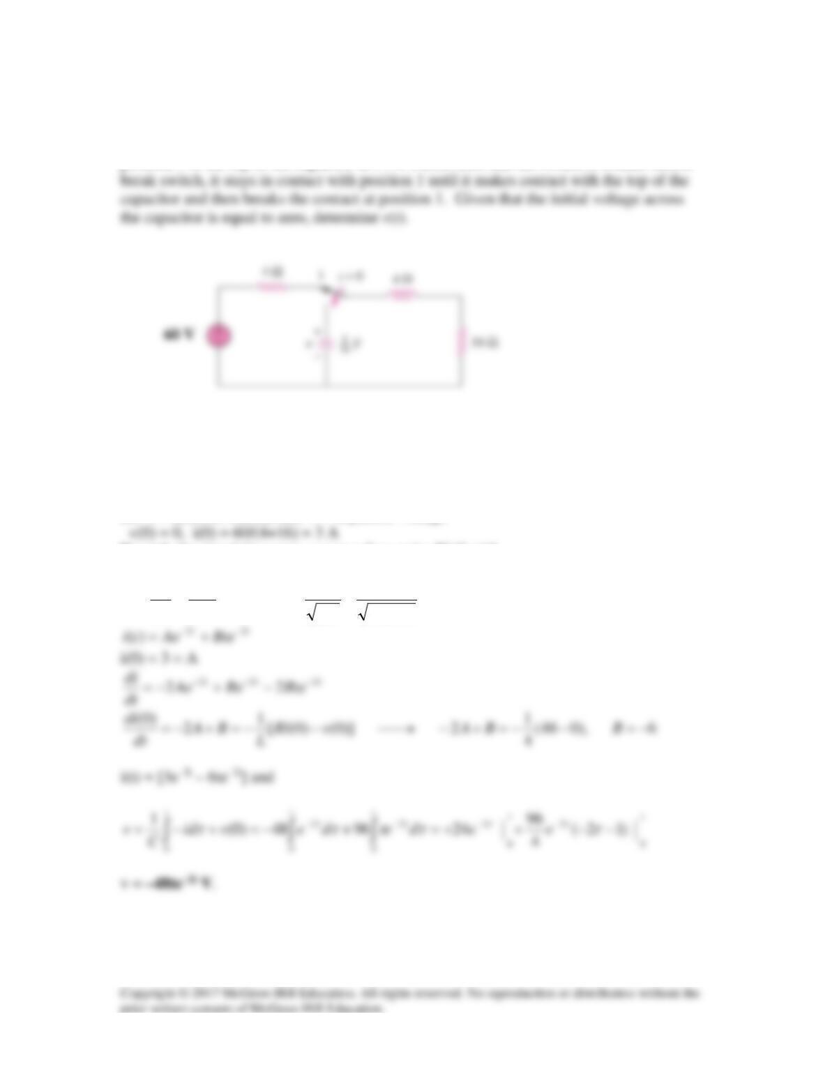
The switch in Fig. 8.105 has been in position 1 for t < 0. At t =0, it is moved from
position 1 to the top of the capacitor at t = 0. Please note that the switch is a make before
Figure 8.105
For Prob. 8.59.
Solution
Let i = inductor current and v = capacitor voltage
For t>0, the circuit becomes a source–free series RLC with
2,2
16/14
11
,2
42
16
2==→======
oo
xLC
xL
R
ωαωα