Solution 8.1
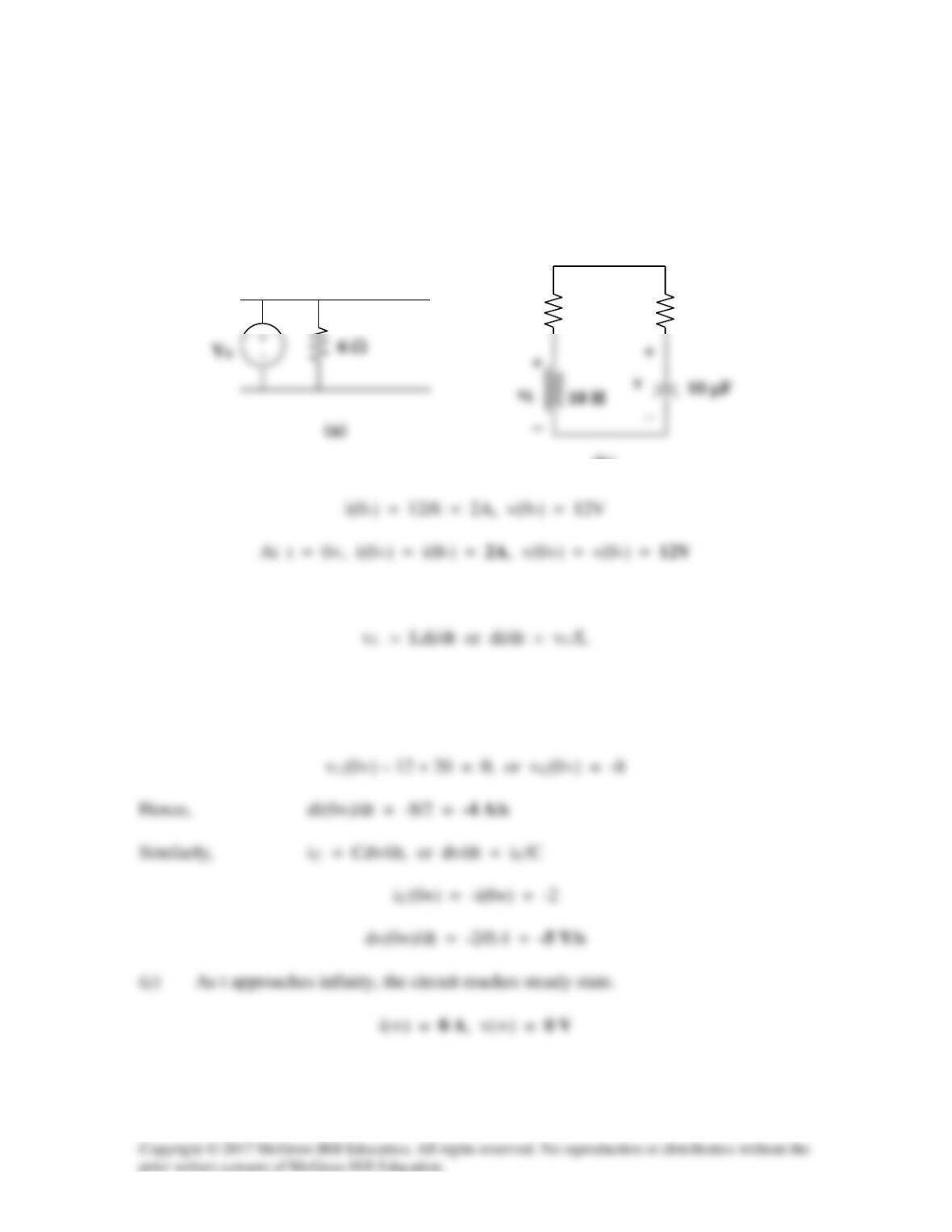
(a) At t = 0–, the circuit has reached steady state so that the equivalent circuit is
shown in Figure (a).
6 Ω
(a)
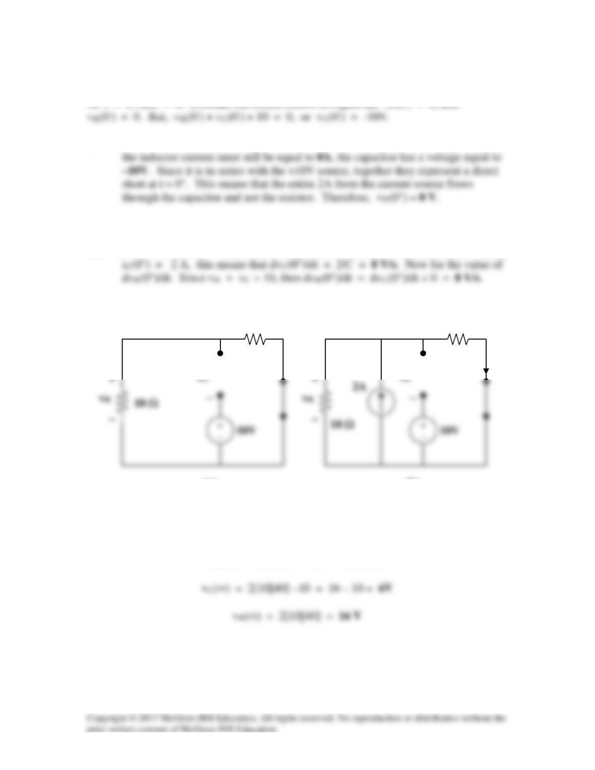
(b) For t > 0, we have the equivalent circuit shown in Figure (b).
Applying KVL at t = 0+, we obtain,
vL(0+) – v(0+) + 10i(0+) = 0
(b)
6 Ω
6 Ω
Solution 8.2
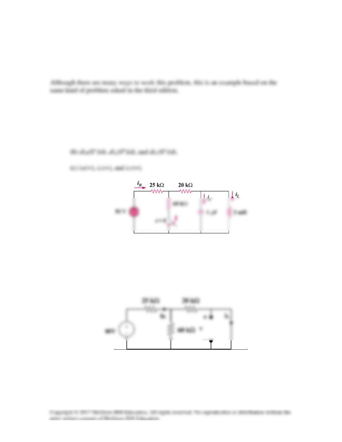
Using Fig. 8.63, design a problem to help other students better understand finding initial
and final values.
Problem
In the circuit of Fig. 8.63, determine:
(a) iR(0+), iL(0+), and iC(0+),
Figure 8.63
Solution
(a) At t = 0-, the equivalent circuit is shown in Figure (a).
(a)
−
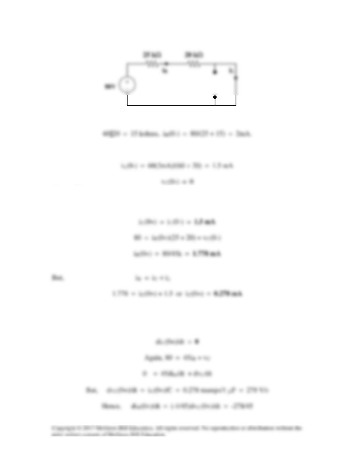
By the current division principle,
At t = 0+,
vC(0+) = vC(0–) = 0
(b) vL(0+) = vC(0+) = 0
But, vL = LdiL/dt and diL(0+)/dt = vL(0+)/L = 0
(b)
(c) As t approaches infinity, we have the equivalent circuit in Figure
(b).
Solution 8.3
(a) At t = 0+, since the inductor current and capacitor voltage cannot change abruptly,
(b) At t = 0+, vL(0+) = 0, therefore LdiL(0+)/dt = vL(0+) = 0, thus, diL/dt = 0A/s,
+
+
(c) As t approaches infinity, we end up with the equivalent circuit shown in
Figure (b).
iL(∞) = 10(2)/(40 + 10) = 400 mA
40 Ω
(a)
+
iL
40 Ω
(b)
+
Solution 8.4
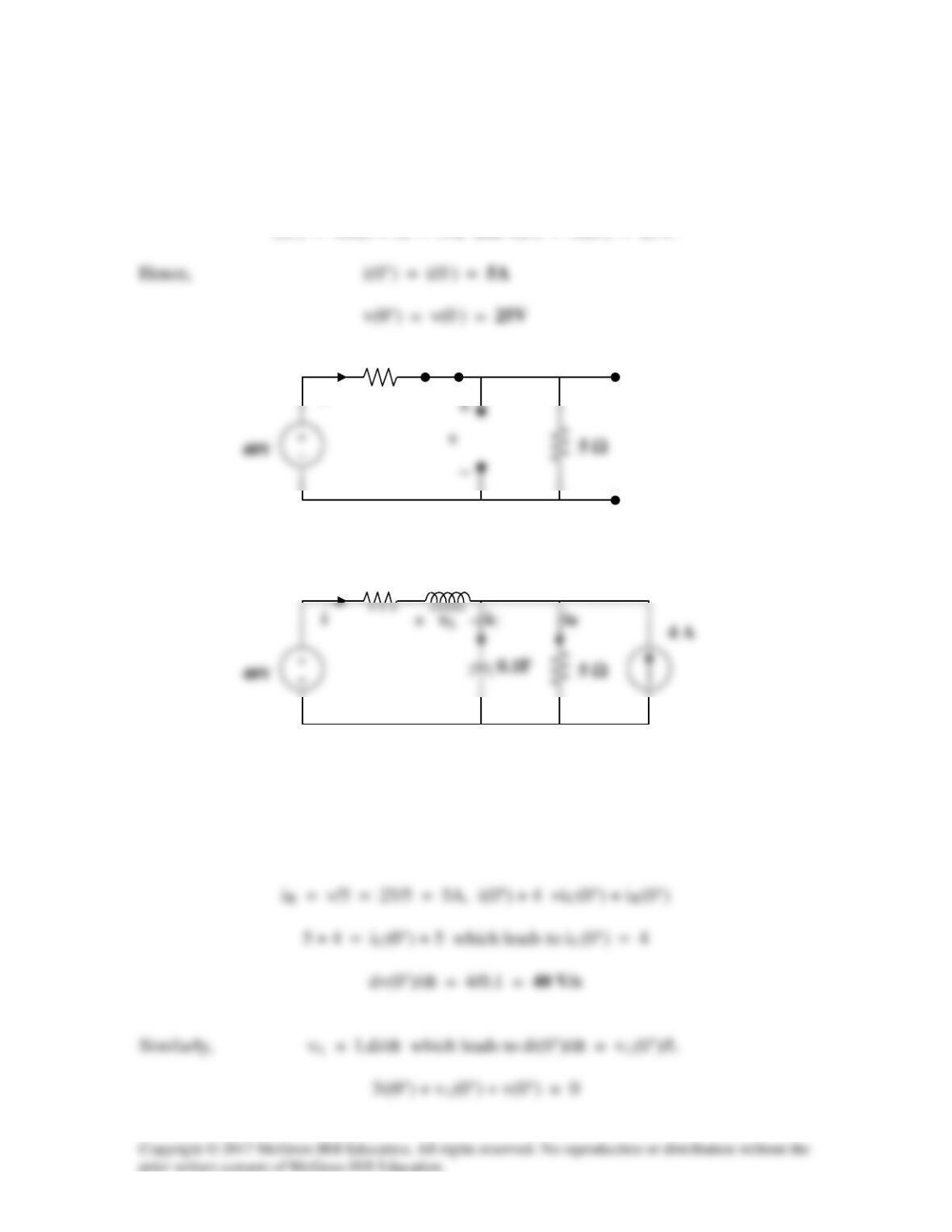
(a) At t = 0–, u(-t) = 1 and u(t) = 0 so that the equivalent circuit is shown in
Figure (a).
i(0–) = 40/(3 + 5) = 5A, and v(0–) = 5i(0–) = 25V.
i
(b) iC = Cdv/dt or dv(0+)/dt = iC(0+)/C
For t = 0+, 4u(t) = 4 and 4u(-t) = 0. The equivalent circuit is shown in Figure (b).
Since i and v cannot change abruptly,
3 Ω
(a)
i
3 Ω
(b)
0.25 H
(c) As t approaches infinity, we have the equivalent circuit in Figure (c).
Solution 8.5
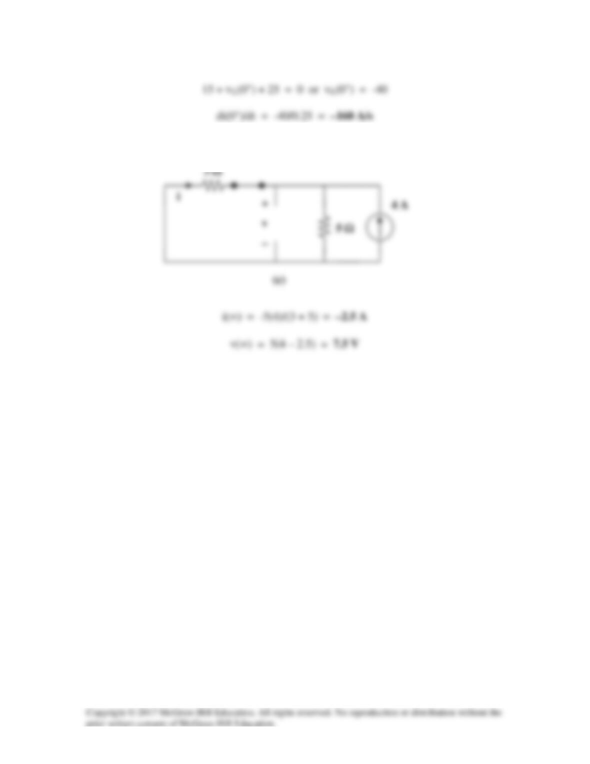
(a) For t < 0, 4u(t) = 0 so that the circuit is not active (all initial conditions = 0).
For t = 0+, 4u(t) = 4. Consider the circuit below.
Since the 4–ohm resistor is in parallel with the capacitor,
(b) di(0+)/dt = d(vR(0+)/R)/dt = (1/R)dvR(0+)/dt = (1/R)dvC(0+)/dt
(c) As t approaches infinity, the circuit is in steady–state.
−
−
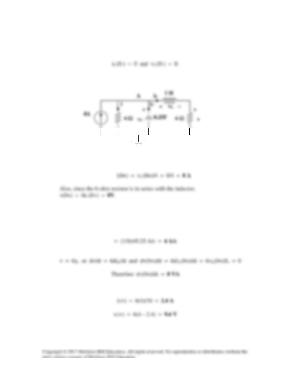
Solution 8.6
(a) Let i = the inductor current. For t < 0, u(t) = 0 so that
(b) Since i(0+) = 0, iC(0+) = VS/RS
(c) As t approaches infinity, the capacitor acts like an open circuit, while the inductor
acts like a short circuit.
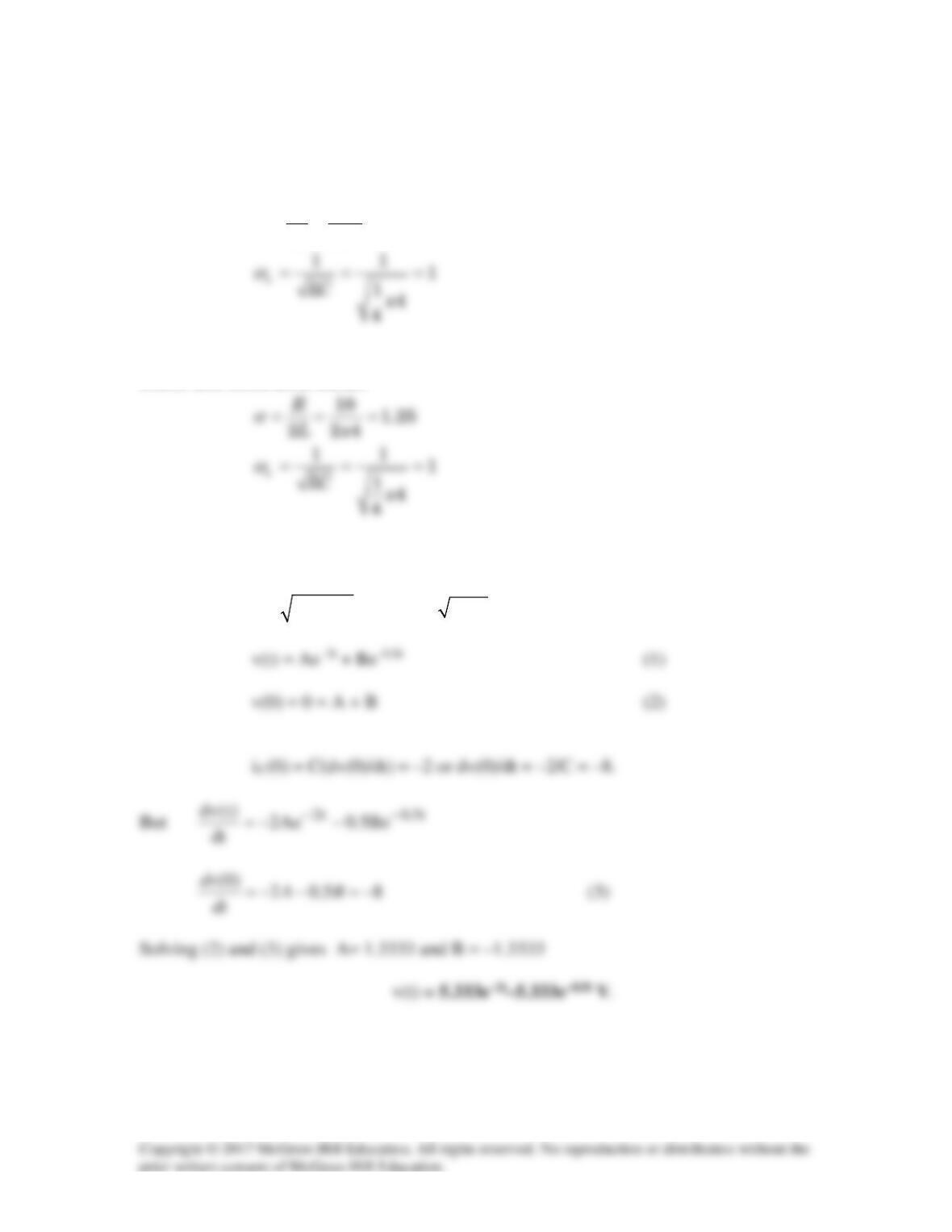
Solution 8.7
α = [R/(2L)] = 20×103/(2×0.2×10–3) = 50×106
Solution 8.8
Design a problem to help other students better understand source-free RLC circuits.
Problem
The branch current in an RLC circuit is described by the differential equation
Solution
s2 + 6s + 9 = 0, thus s1,2 =
2
3666 2−±−
= -3, repeated roots.
Solution 8.9
s2 + 10s + 25 = 0, thus s1,2 =
2
101010 −±−
= –5, repeated roots.
Solution 8.10
The differential equation that describes the current in an RLC network is
Solution
s2 + 5s + 4 = 0, thus s1,2 =
5 25 16
2
−± −
= –4, –1.
Solution 8.11
s2 + 2s + 1 = 0, thus s1,2 =
2
442 −±−
= –1, repeated roots.
Solution 8.12
(a) Overdamped when C > 4L/(R2) = 4×1.5/2500 = 2.4×10⁻³, or
Solution 8.13
Let R||60 = Ro. For a series RLC circuit,
Solution 8.14
When the switch is in position A, v(0–)= 0 and iL(0) = 80/40 = 2 A. When the switch is in
position B, we have a source-free series RCL circuit.
10 1.25
2 24
R
Lx
α
= = =
When the switch is in position A, v(0–)= 0. When the switch is in position B, we have a
source-free series RCL circuit.
Since
o
αω
>
, we have overdamped case.
22
1, 2
1.25 1.5625 1 1.5664, 0.9336
o
s
α αω
=−± − =− ± −=− −
–0.5 and –2
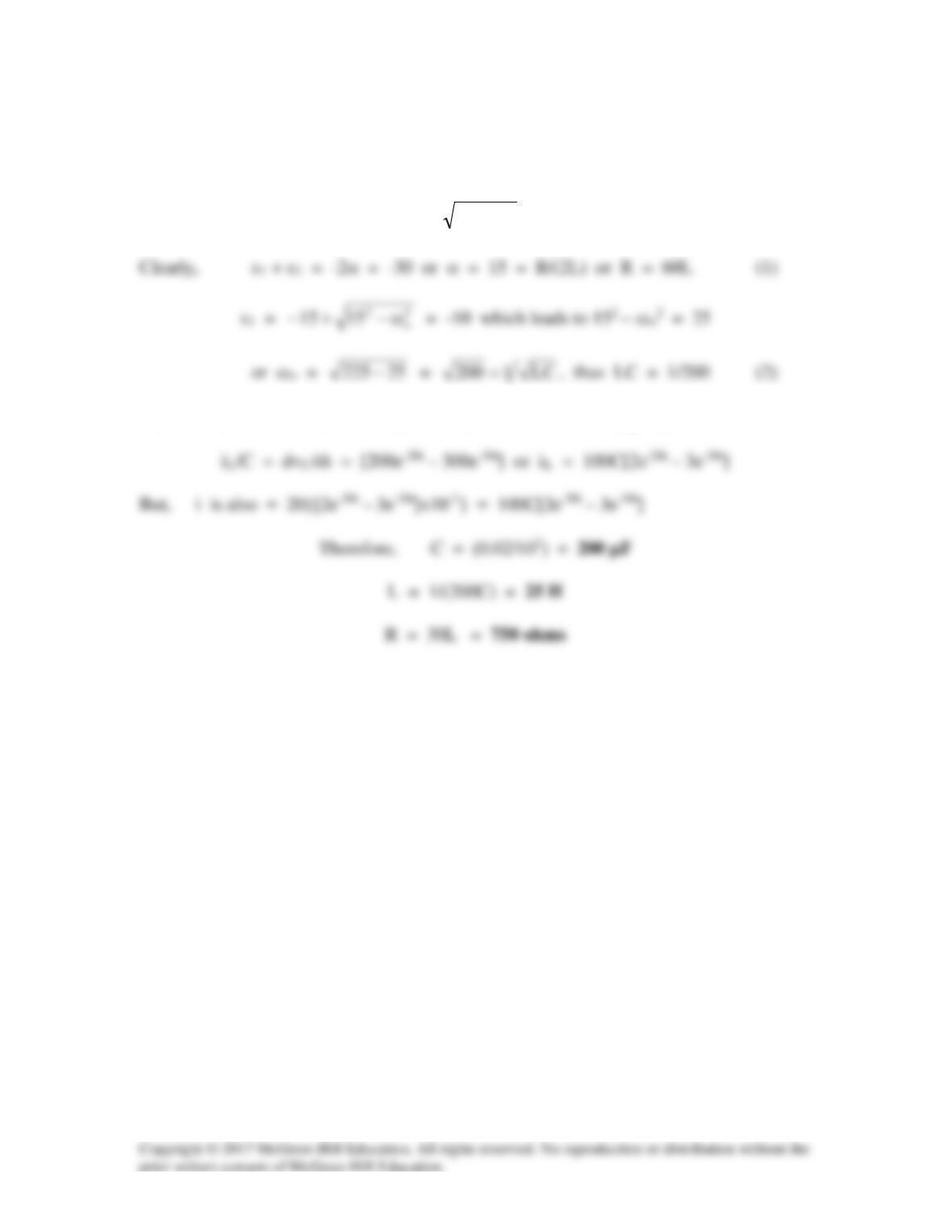
Solution 8.15
Given that s1 = -10 and s2 = –20, we recall that
s1,2 =
2
o
2ω−α±α−
= -10, -20
Since we have a series RLC circuit, iL = iC = CdvC/dt which gives,
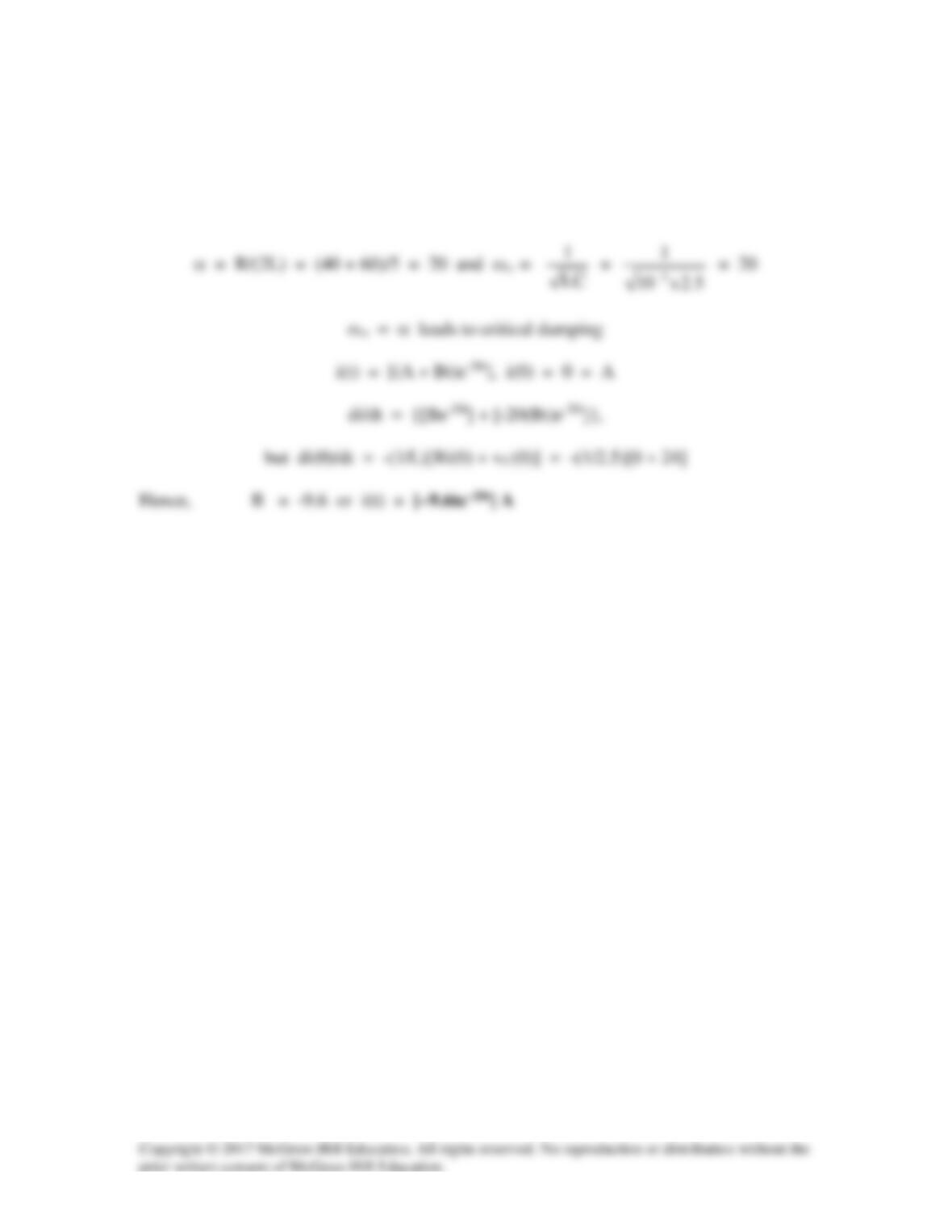
Solution 8.16
At t = 0, i(0) = 0, vC(0) = 40×30/50 = 24V
For t > 0, we have a source–free RLC circuit.
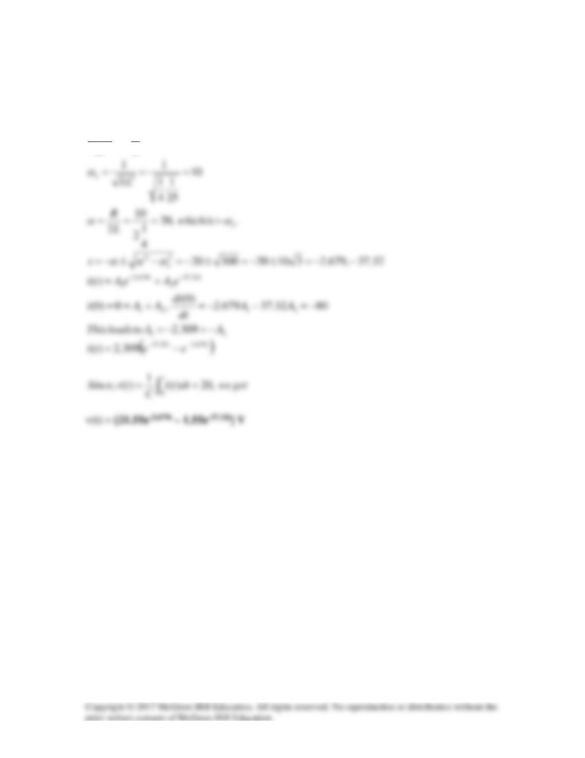
Solution 8.17
80)200(4)(
1)0(
2054)0(,0)0(
00
00
VRI
Ldt
di
xVvIi
−=+−=+−=
=====