Solution 4.1
i
5 Ω
25 Ω
io
Solution 4.2
Using Fig. 4.70, design a problem to help other students better understand linearity.
Problem
Find vo in the circuit of Fig. 4.70. If the source current is reduced to 1
µ
A, what is vo?
Figure 4.70
Solution
,3)24(6 Ω=+
A
1
ii 21 ==
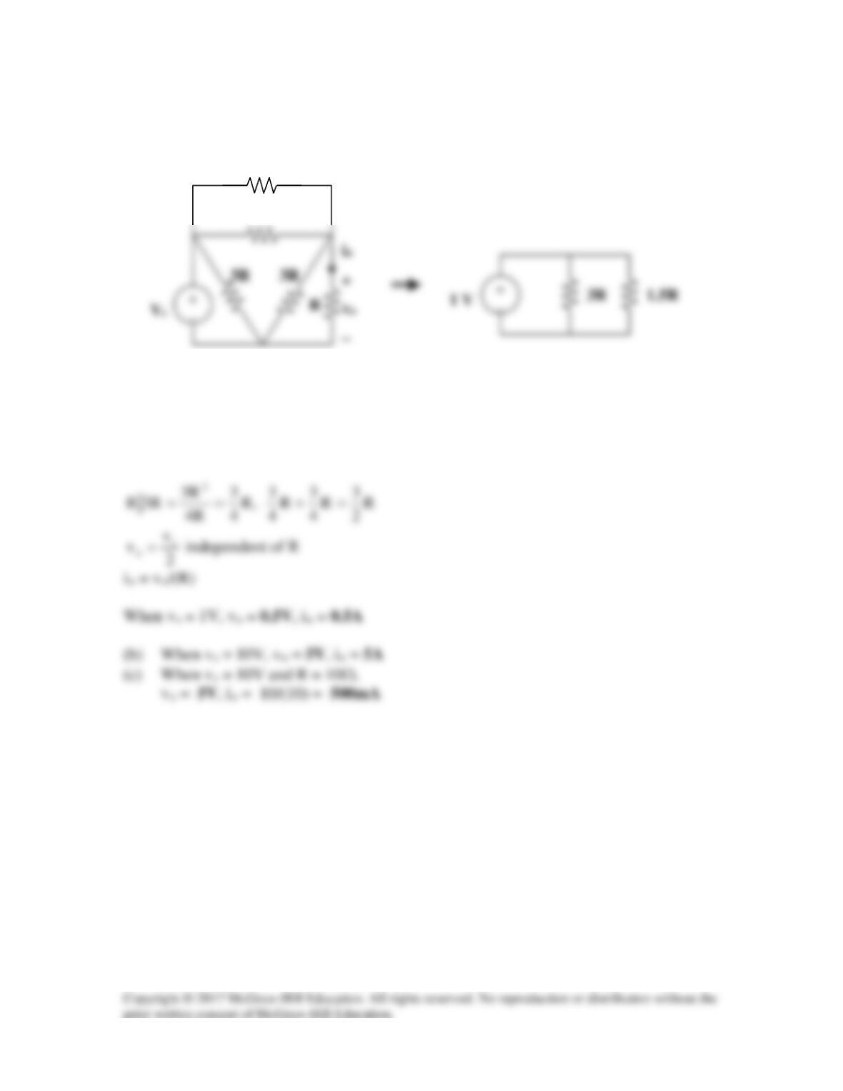
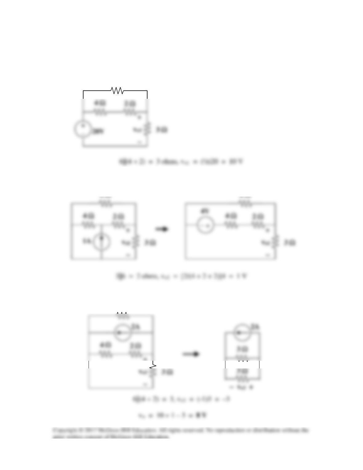
Solution 4.3
(a) We transform the Y sub-circuit to the equivalent
∆
.
(b)
(a)
R
3R
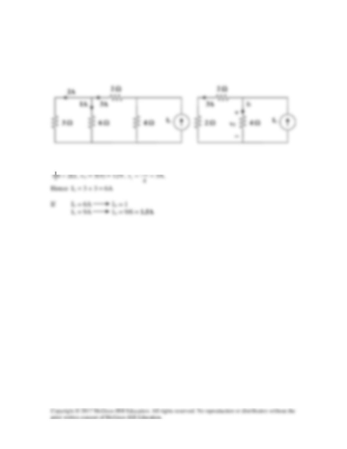
Solution 4.4
If Io = 1, the voltage across the 6Ω resistor is 6V so that the current through the 3Ω
resistor is 2A.
v
(a)
(b)
Solution 4.5
If vo = 1V,
V21
3
1
V
1
=+
=
v1
2 Ω
3 Ω
vo
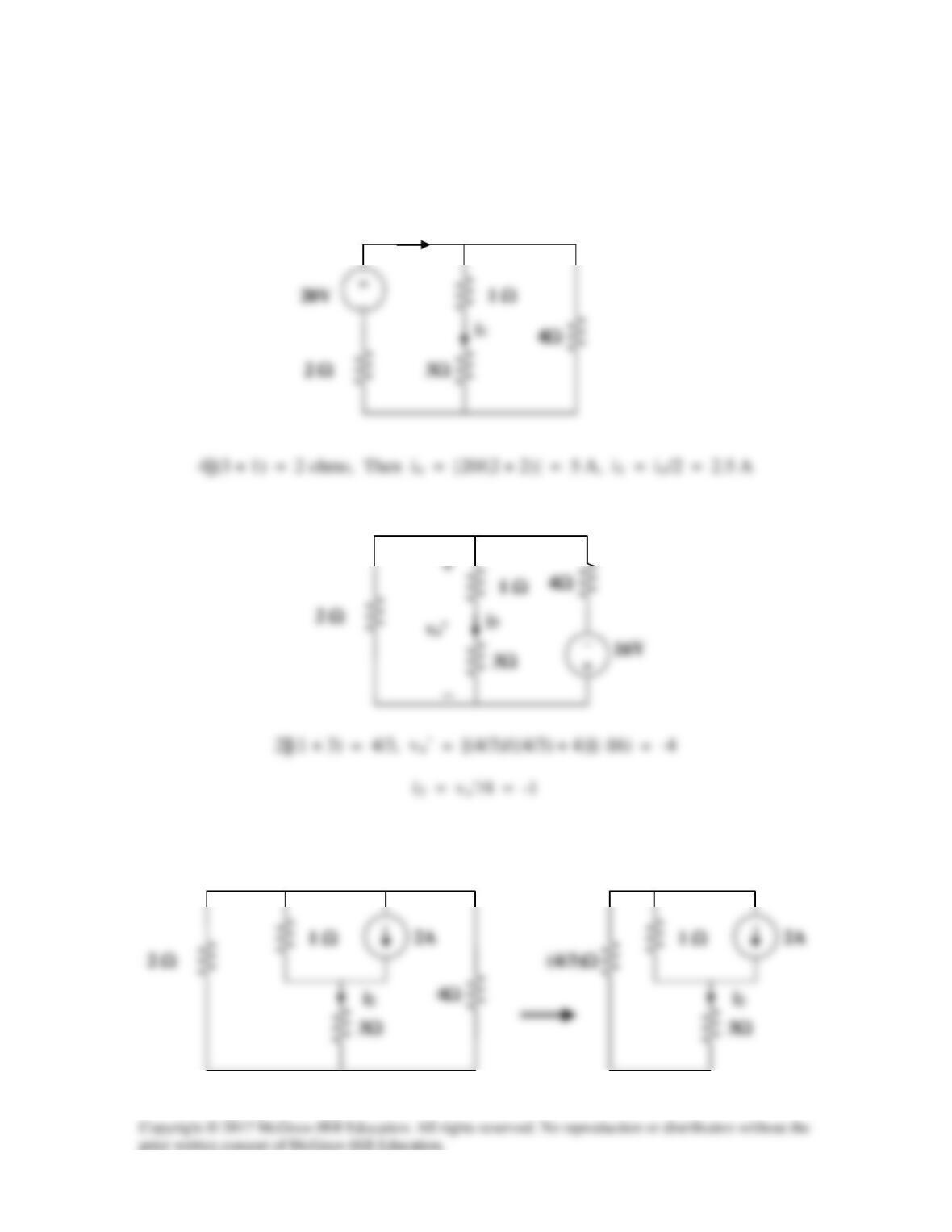
Solution 4.6
Due to linearity, from the first experiment,
Applying this to other experiments, we obtain:
Experiment Vs Vo
2 48 16 V
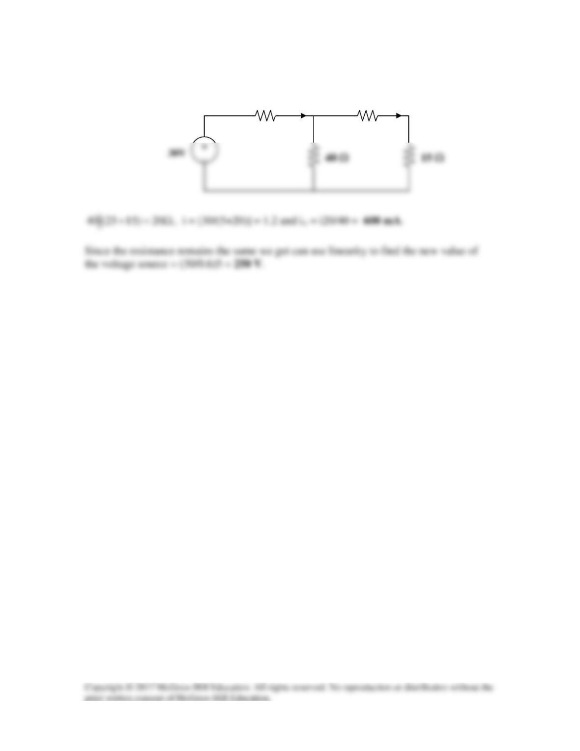
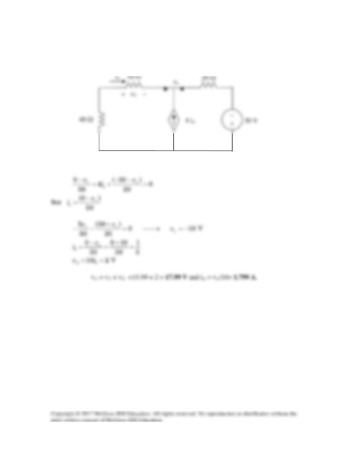
Solution 4.7
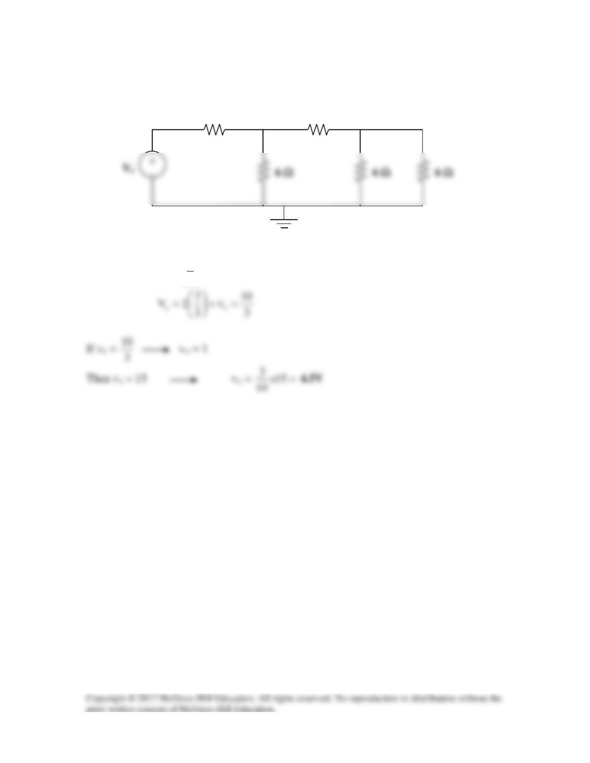
Use linearity and the assumption that Vx = 1V to find the actual value of Vo in Fig. 4.75.
.
Figure 4.75
For Prob. 4.7.
Solution
Step 1. If we let Vx = 1 volt then I10 = 0.1 amp which leads to V30–10 = 0.1×40 = 4
Step 2. Since the current source is 1 amp which is –5(–0.2) then the voltage Vx =
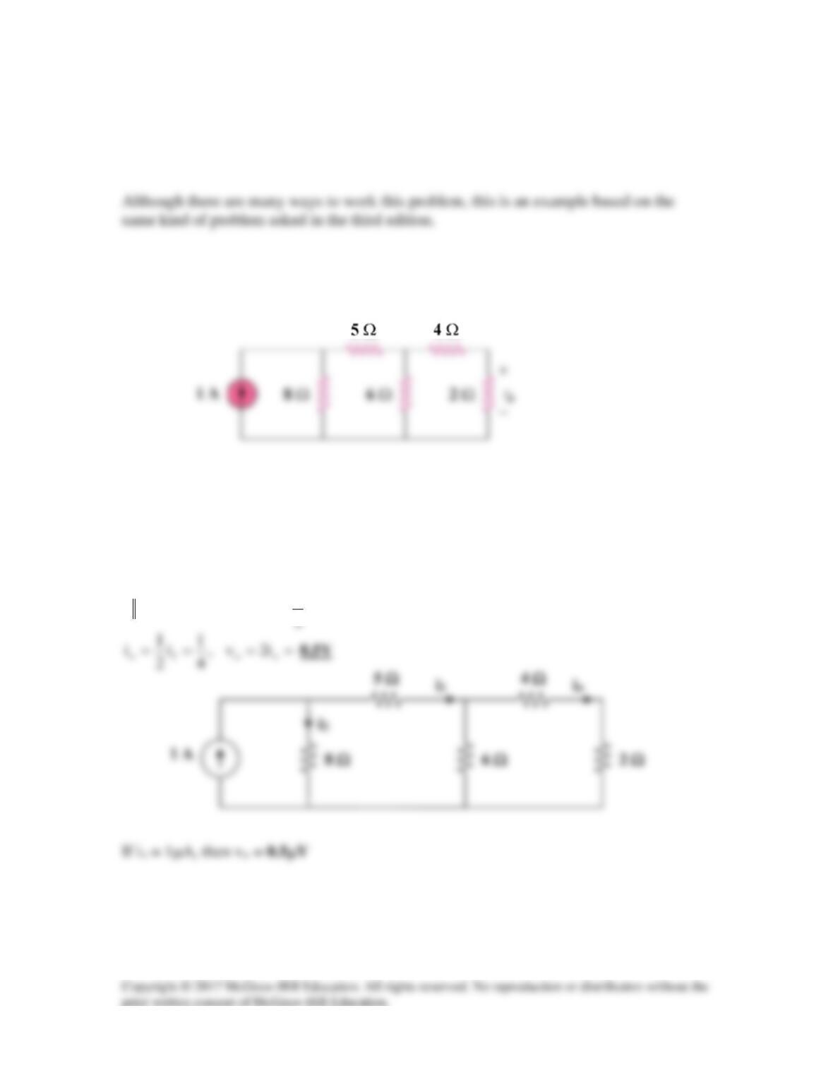
If Vo = 1V, then the current through the 2-Ω and 4-Ω resistors is ½ = 0.5. The voltage
1
Solution 4.8
To find V2, consider the circuit below.
V
1
V
1
Solution 4.9
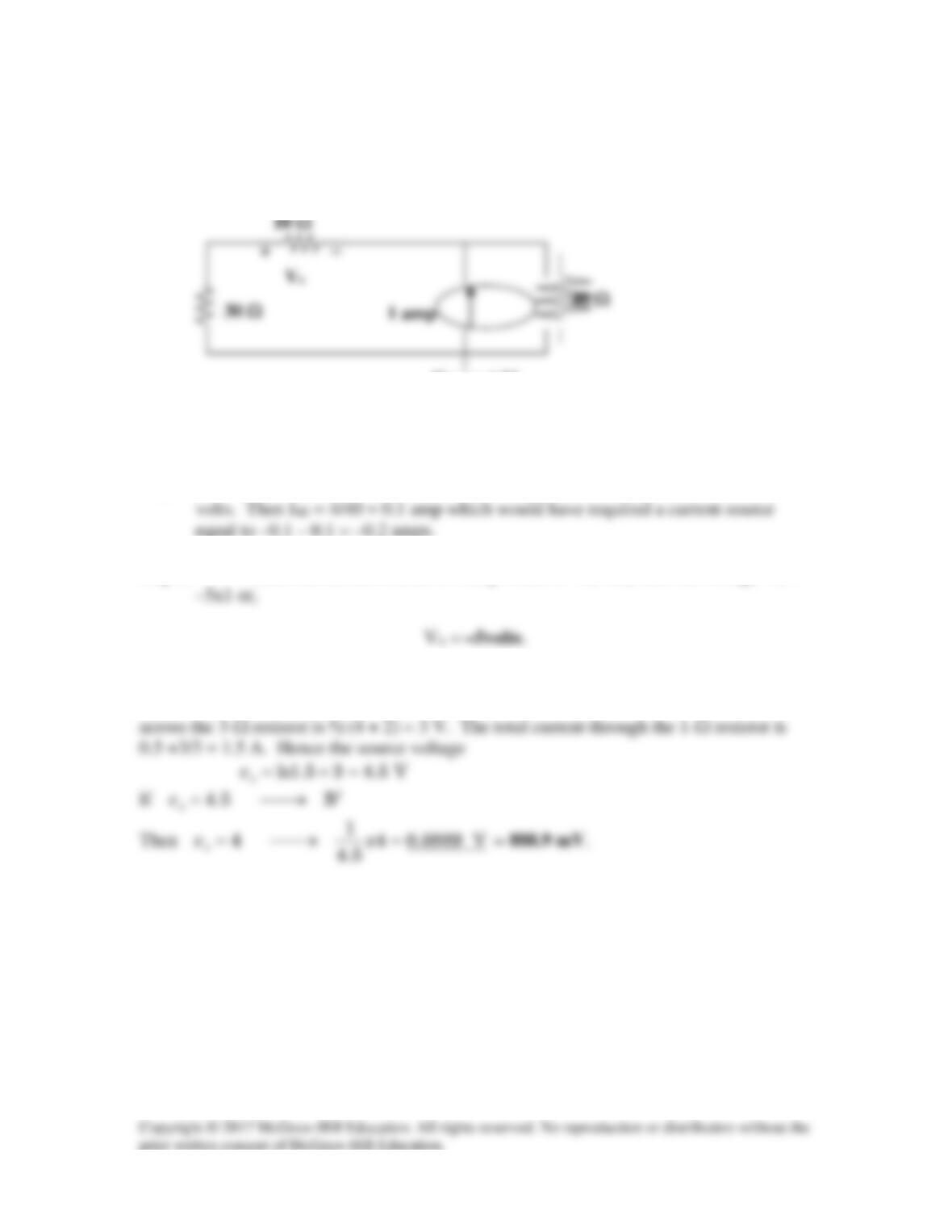
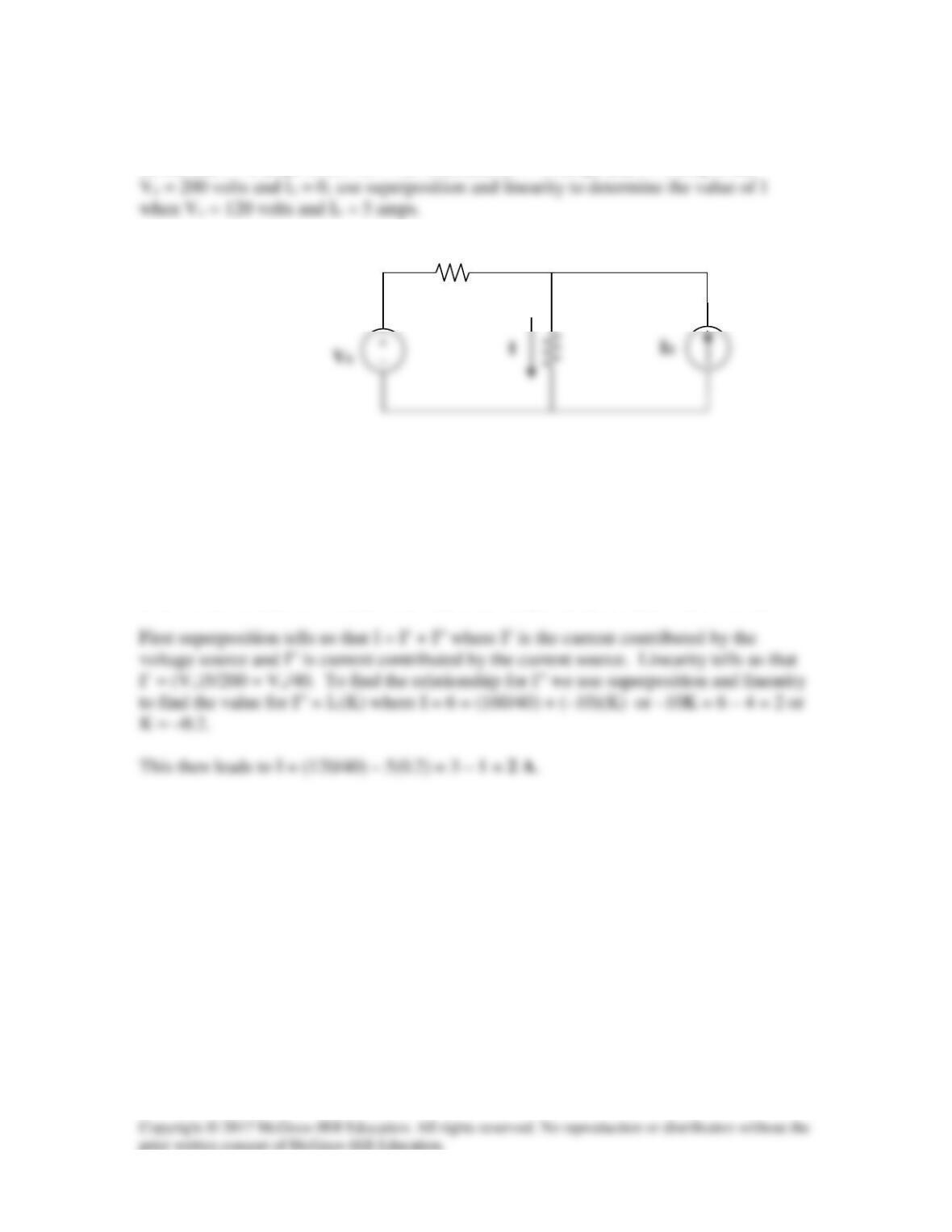
Given that I = 6 amps when Vs = 160 volts and Is = –10 amps and I = 5 amp when
Figure 4.77
For Prob. 4.9.
Solution
At first this appears to be a difficult problem. However, if you take it one step at a time
then it is not as hard as it seems. The important thing to keep in mind is that it is linear!
Solution 4.10
Using Fig. 4.78, design a problem to help other students better understand superposition. Note,
Problem
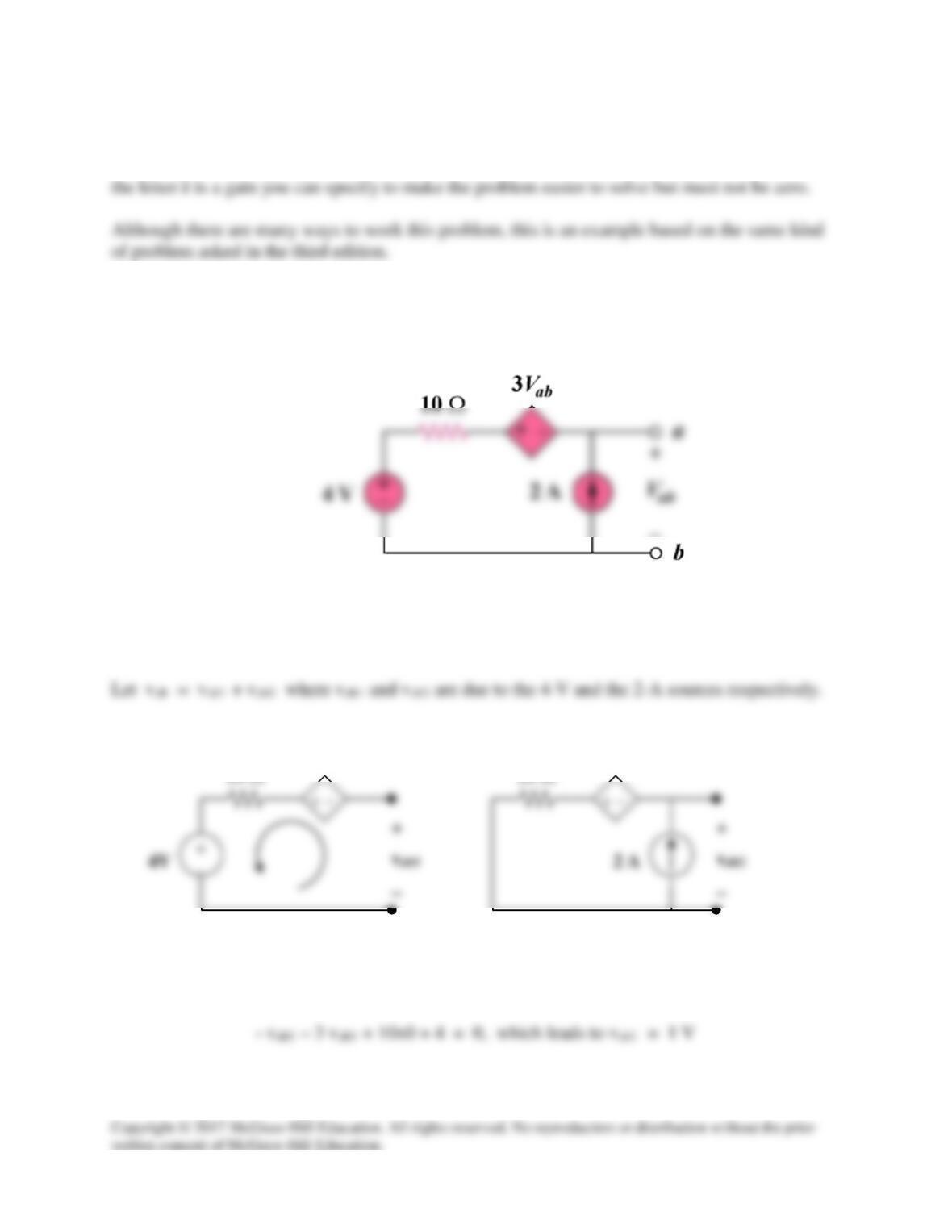
For the circuit in Fig. 4.78, find the terminal voltage Vab using superposition.
Figure 4.78
For Prob. 4.10.
Solution
For vab1, consider Fig. (a). Applying KVL gives,
(a)
3vab1
10 Ω
(b)
3vab2
10 Ω
For vab2, consider Fig. (b). Applying KVL gives,
Solution 4.11
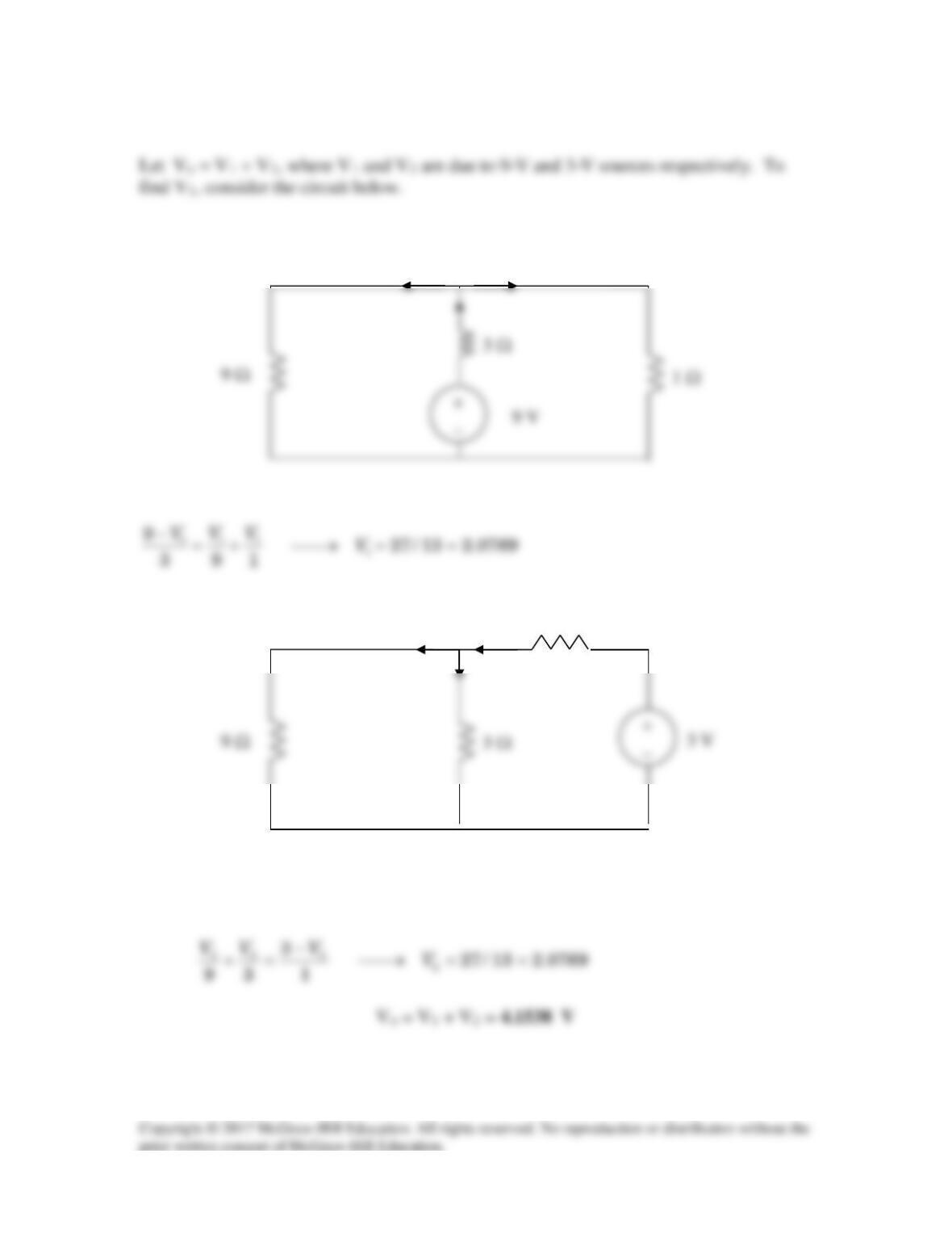
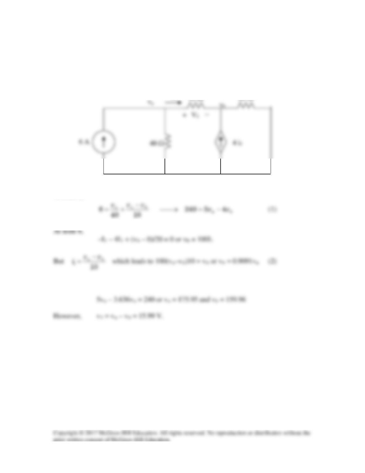
Let vo = v1 + v2, where v1 and v2 are due to the 6-A and 80-V sources respectively. To
find v1, consider the circuit below.
At node a,
Substituting (2) into (1),
I
1
To find v2, consider the circuit below.
Solution 4.12
Let vo = vo1 + vo2 + vo3, where vo1, vo2, and vo3 are due to the 2-A, 12-V, and 19-V
sources respectively. For vo1, consider the circuit below.
5 Ω
4 Ω
i
5 Ω
5 Ω
For vo2, consider the circuit below.
For vo3, consider the circuit shown below.
4 Ω
2A
2A
6 Ω
4 Ω
5 Ω
6 Ω
5 Ω
4 Ω
5 Ω
5 Ω
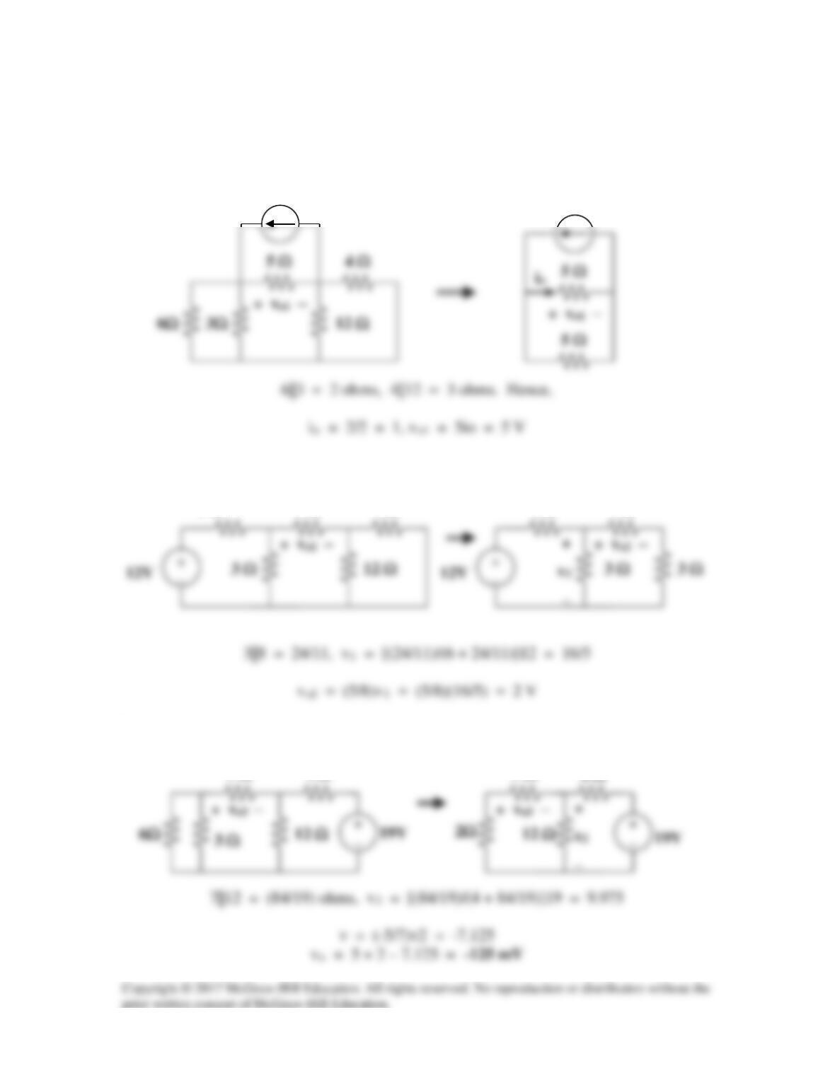
Solution 4.13
Let
12 3o
v vv v=++
, where v1, v2, and v3 are due to the independent sources. To
find v1, consider the circuit below.
+
To find v2, consider the circuit below.
+
_
_
4 A
Solution 4.14
Let vo = vo1 + vo2 + vo3, where vo1, vo2 , and vo3, are due to the 20-V, 1-A, and 2-A
sources respectively. For vo1, consider the circuit below.
+
4 Ω
2 Ω
For vo2, consider the circuit below.
4 Ω
2 Ω
6 Ω
4 Ω
2 Ω
6 Ω
For vo3, consider the circuit below.
4 Ω
2 Ω
3 Ω
3 Ω
6 Ω
+
6 Ω
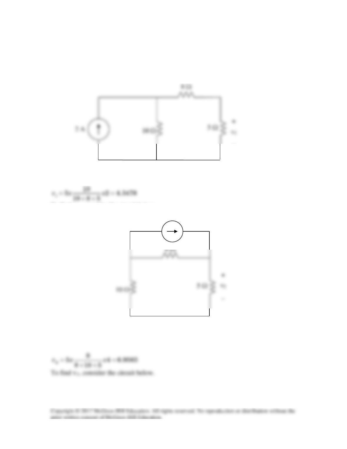
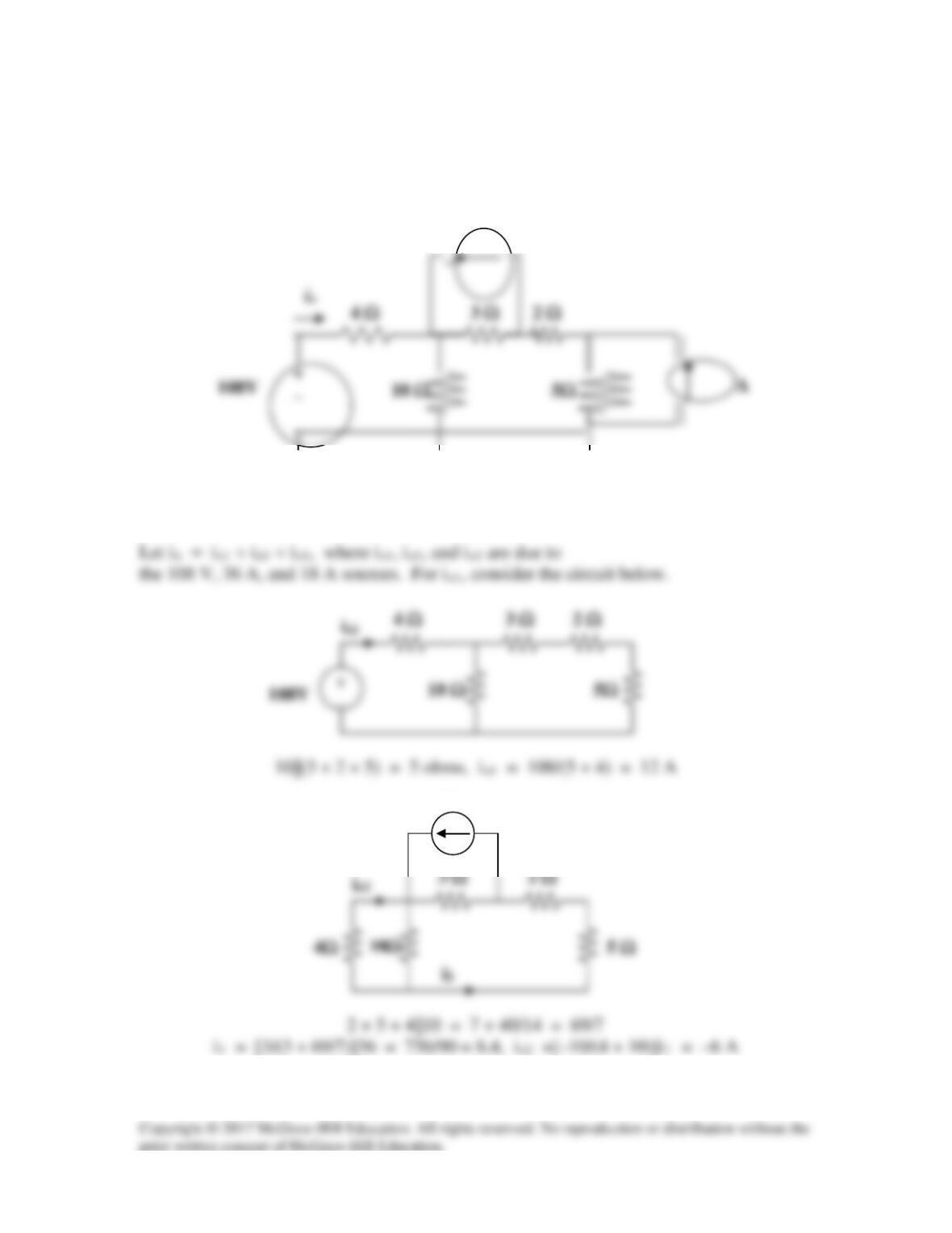
Solution 4.15
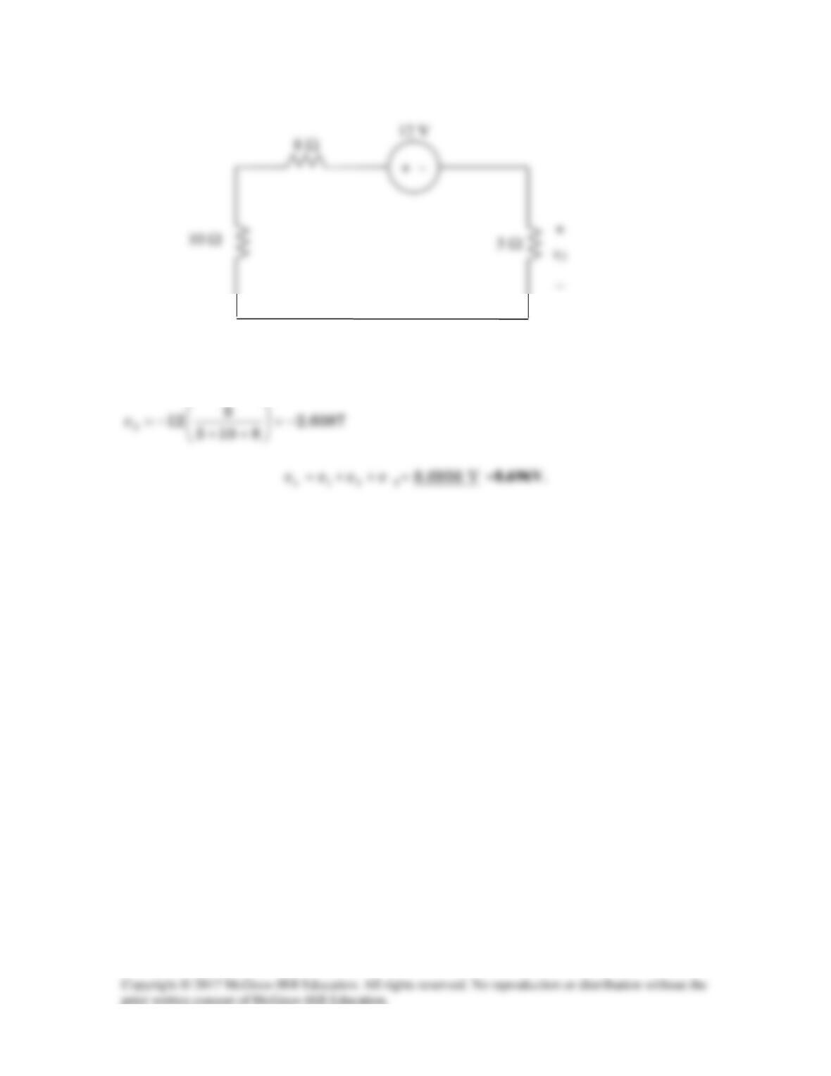
Let i = i1 + i2 + i3, where i1 , i2 , and i3 are due to the 20-V, 2-A, and 16-V sources. For
i1, consider the circuit below.
For i3, consider the circuit below.
i
For i2, consider the circuit below.
i
i
i
o
Using the current division principle.
i2 = [1/(1 + 13/2)]2 = 3/8 = 0.375
Solution 4.16
Given the circuit in Fig. 4.84, use superposition to obtain io.
Figure 4.84
For Prob. 4.16.
For io2, consider the circuit below.
36A
36 A