Solution 8.18
When the switch is off, we have a source-free parallel RLC circuit.
5.0
2
1
,2
125.0
11 ===== RC
xLC
o
αω
Solution 8.19
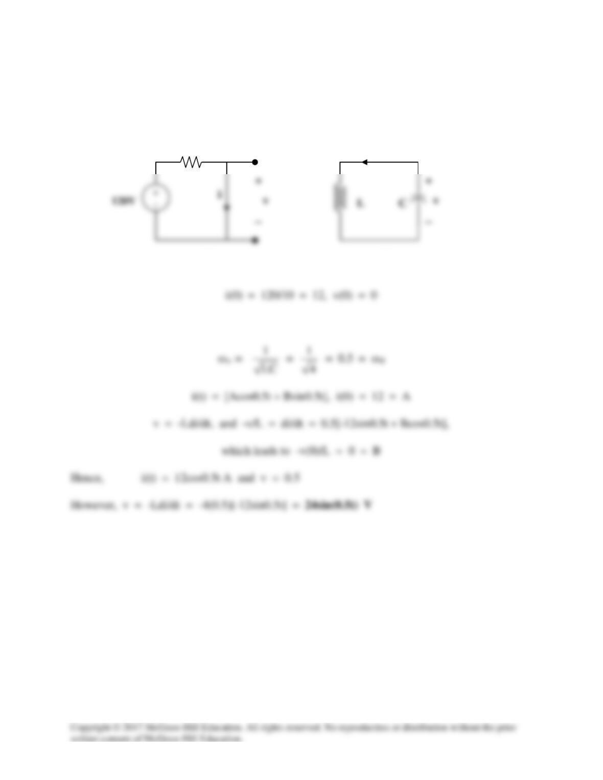
For t < 0, the equivalent circuit is shown in Figure (a).
For t > 0, we have a series RLC circuit as shown in Figure (b) with R = 0 = α.
10 Ω
(a)
(b)
i
Solution 8.20
For t < 0, the equivalent circuit is as shown below.
For t > 0, we have a series RLC circuit.
Since α is less than ωo, we have an under-damped response.
Solution 8.21
By combining some resistors, the circuit is equivalent to that shown below.
60||(15 + 25) = 24 ohms.
For t > 0, we have a series RLC circuit. R = 30 ohms, L = 3 H, C = (1/27) F
Solution 8.22
Compare the characteristic equation with eq. (8.8), i.e.
Solution 8.23
Let Co = C + 0.01. For a parallel RLC circuit,
Solution 8.24
When the switch is in position A, the inductor acts like a short circuit so
When the switch is in position B, we have a source-free parallel RCL circuit
11
Solution 8.25
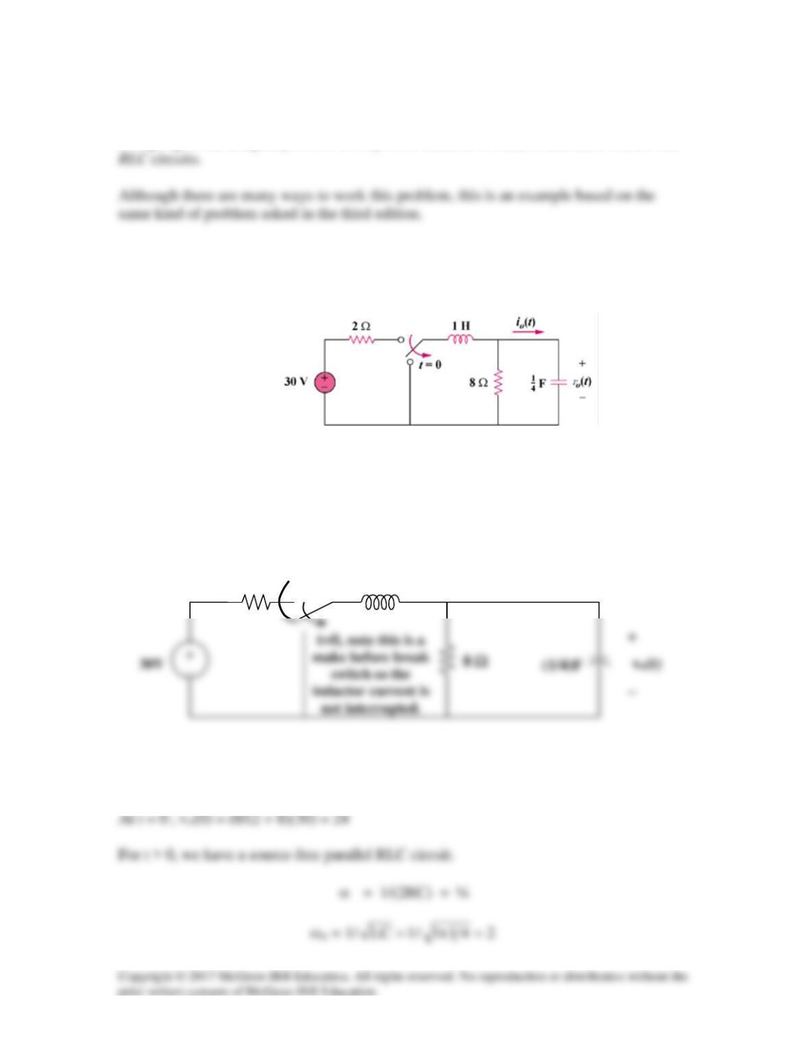
Using Fig. 8.78, design a problem to help other students to better understand source-free
Problem
In the circuit in Fig. 8.78, calculate io(t) and vo(t) for t > 0.
Figure 8.78
Solution
In the circuit in Fig. 8.76, calculate io(t) and vo(t) for t>0.
Figure 8.78 For Problem 8.25.
2 Ω
1 H
io(t)
Since α is less than ωo, we have an under-damped response.
9843.1)16/1(4
22
od
=−=α−ω=ω
Solution 8.26
These roots indicate an underdamped circuit which has the generalized solution given as:
i(t) = Is + [(A1cos(4t) + A2sin(4t))e-t],
Solution 8.27
s2 + 4s + 8 = 0 leads to s =
2j2
2
32164 ±−=
−±−
Solution 8.28
The characteristic equation is
2 22
1 11
But [is/C] = 10 or is = 0.2×10 = 2
Solving (1) and (2) gives –6.45(–1–B) – 1.5505B = 0 or (6.45–1.5505)B = –6.45
Solution 8.29
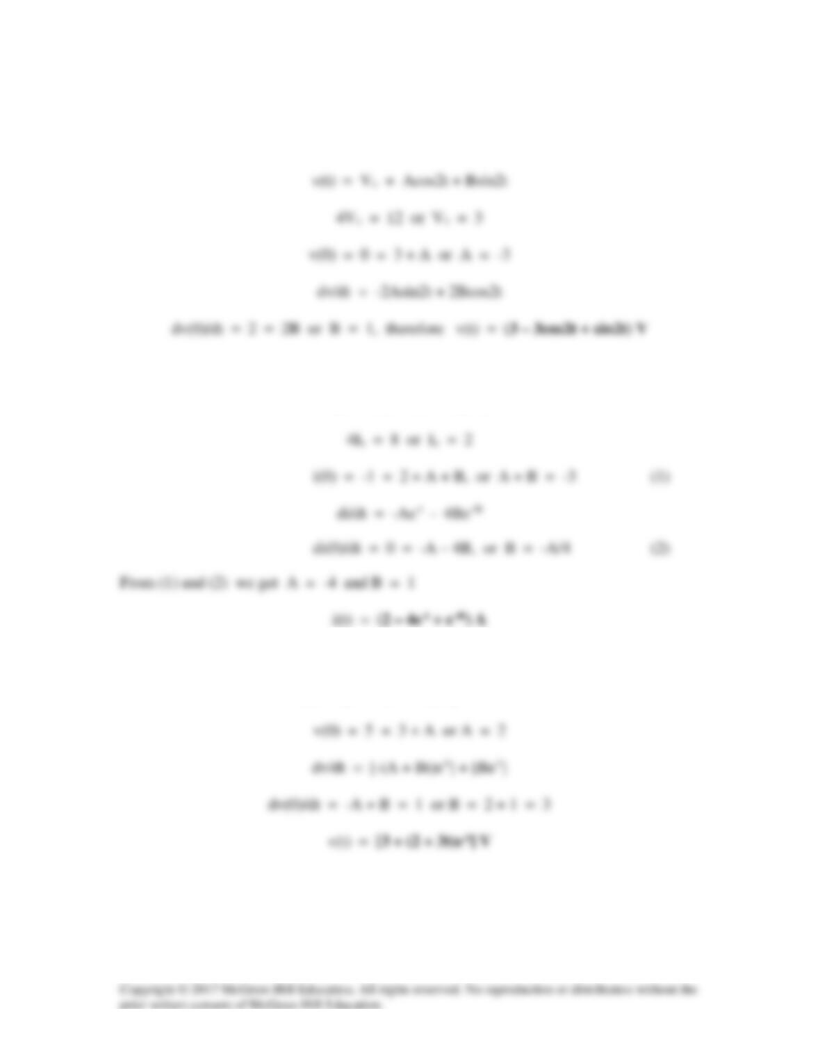
(a) s2 + 4 = 0 which leads to s1,2 = ±j2 (an undamped circuit)
(b) s2 + 5s + 4 = 0 which leads to s1,2 = -1, -4
i(t) = (Is + Ae-t + Be–4t)
(c) s2 + 2s + 1 = 0, s1,2 = -1, -1
v(t) = [Vs + (A + Bt)e-t], Vs = 3.
(d) s2 + 2s +5 = 0, s1,2 = -1 + j2, -1 – j2
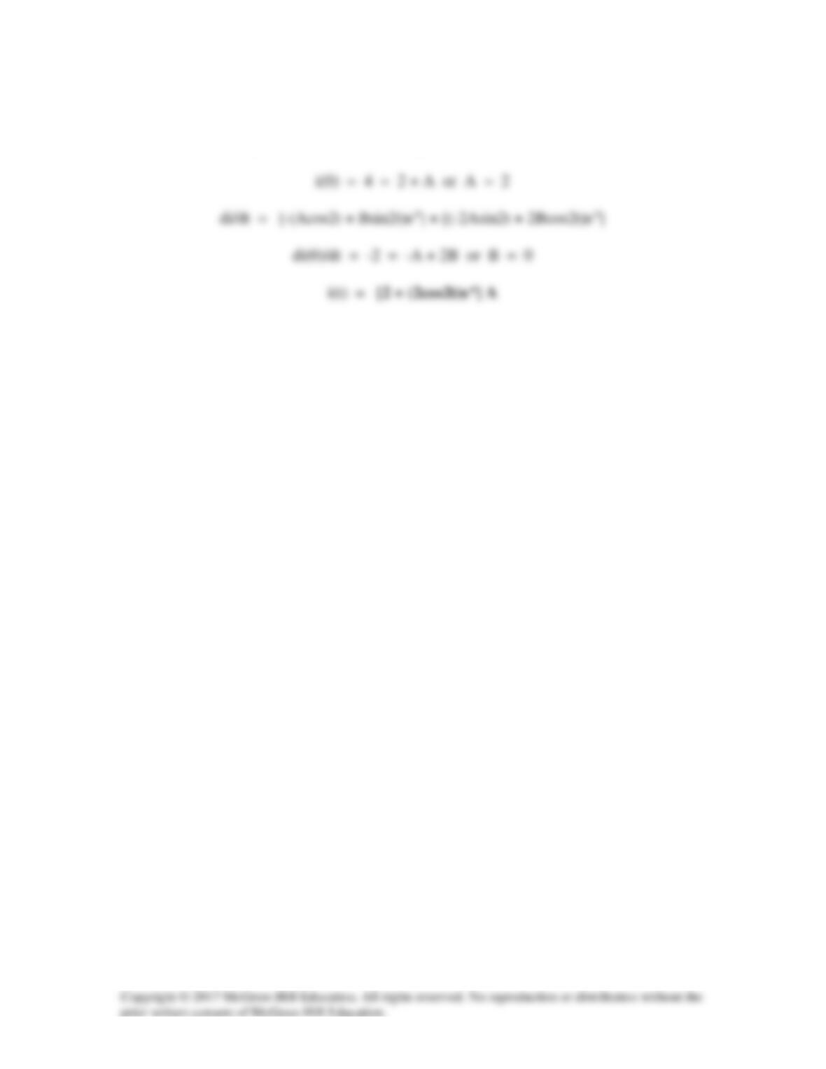
i(t) = [Is + (Acos2t + Bsin2t)e-t], where 5Is = 10 or Is = 2
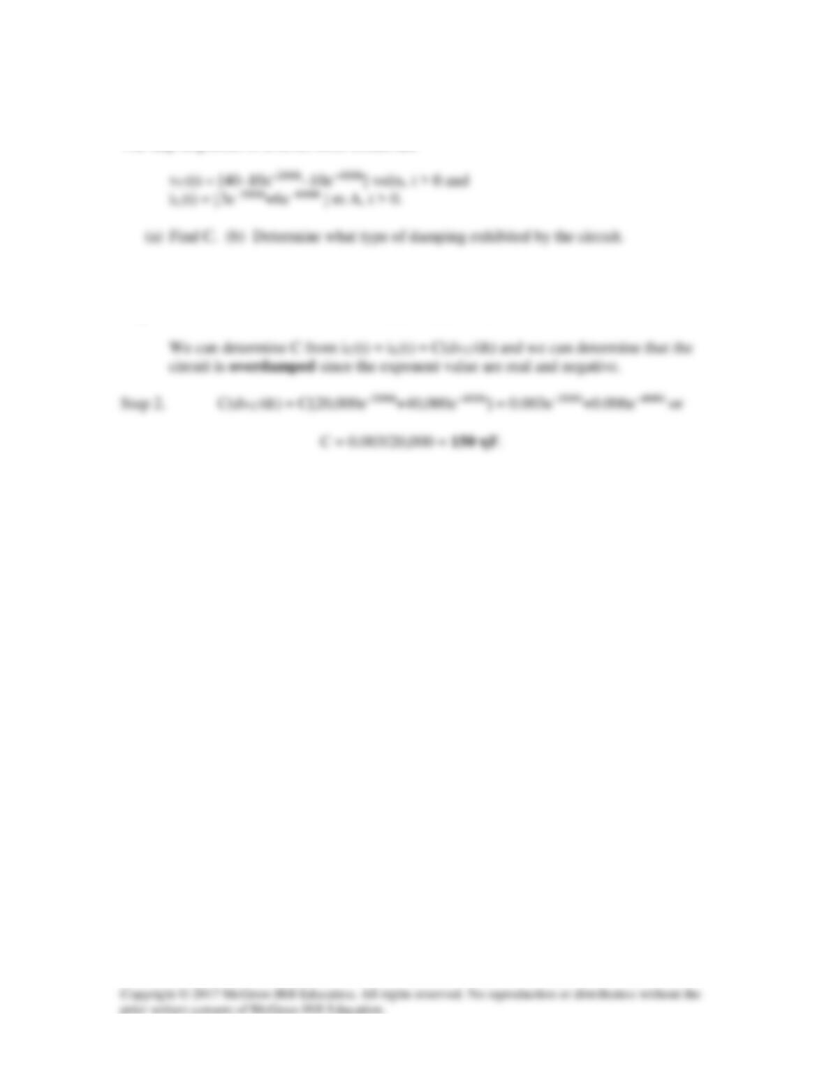
Solution 8.30
The step responses of a series RLC circuit are
Solution
Step 1. For a series RLC circuit, iR(t) = iL(t) = iC(t).
Solution 8.31
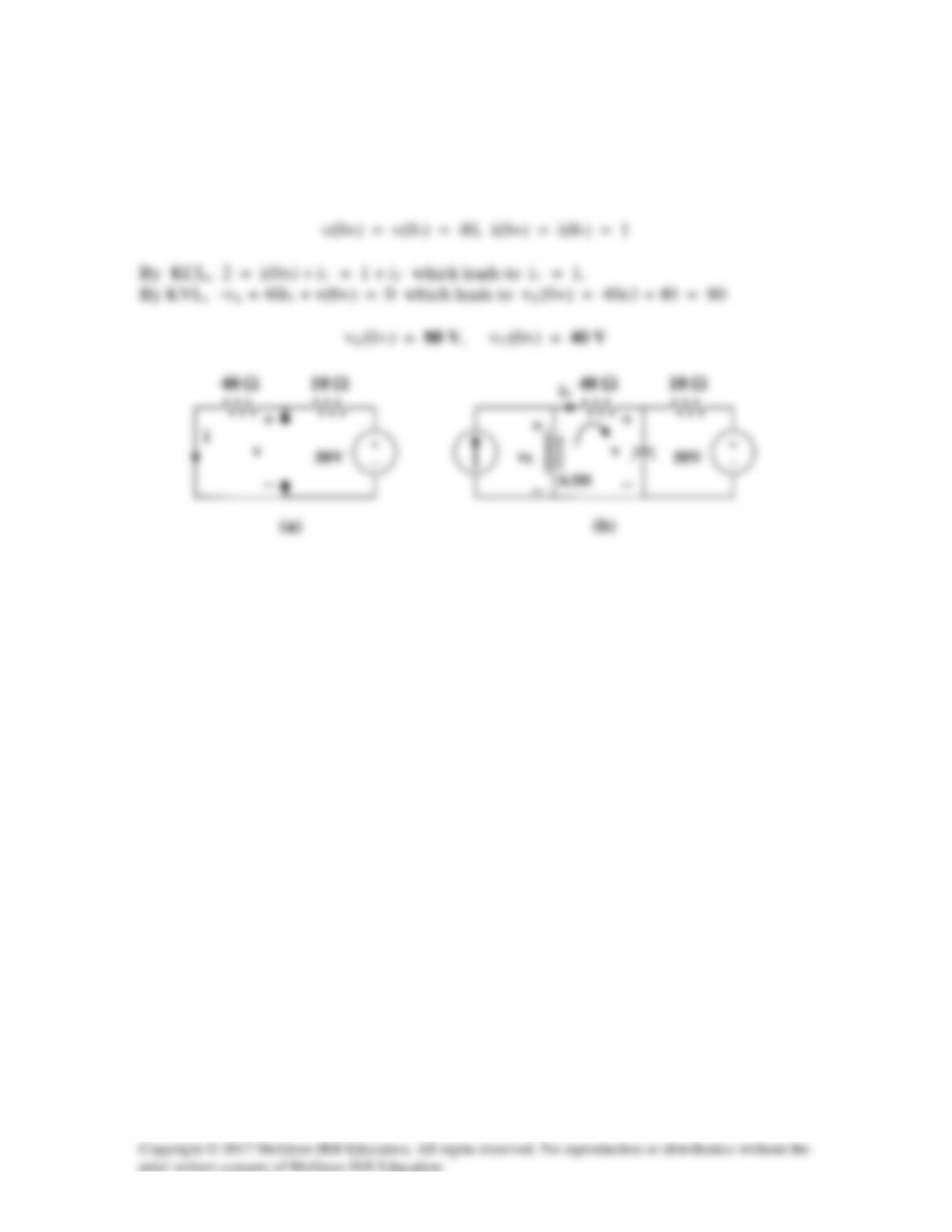
For t = 0-, we have the equivalent circuit in Figure (a). For t = 0+, the equivalent
circuit is shown in Figure (b). By KVL,
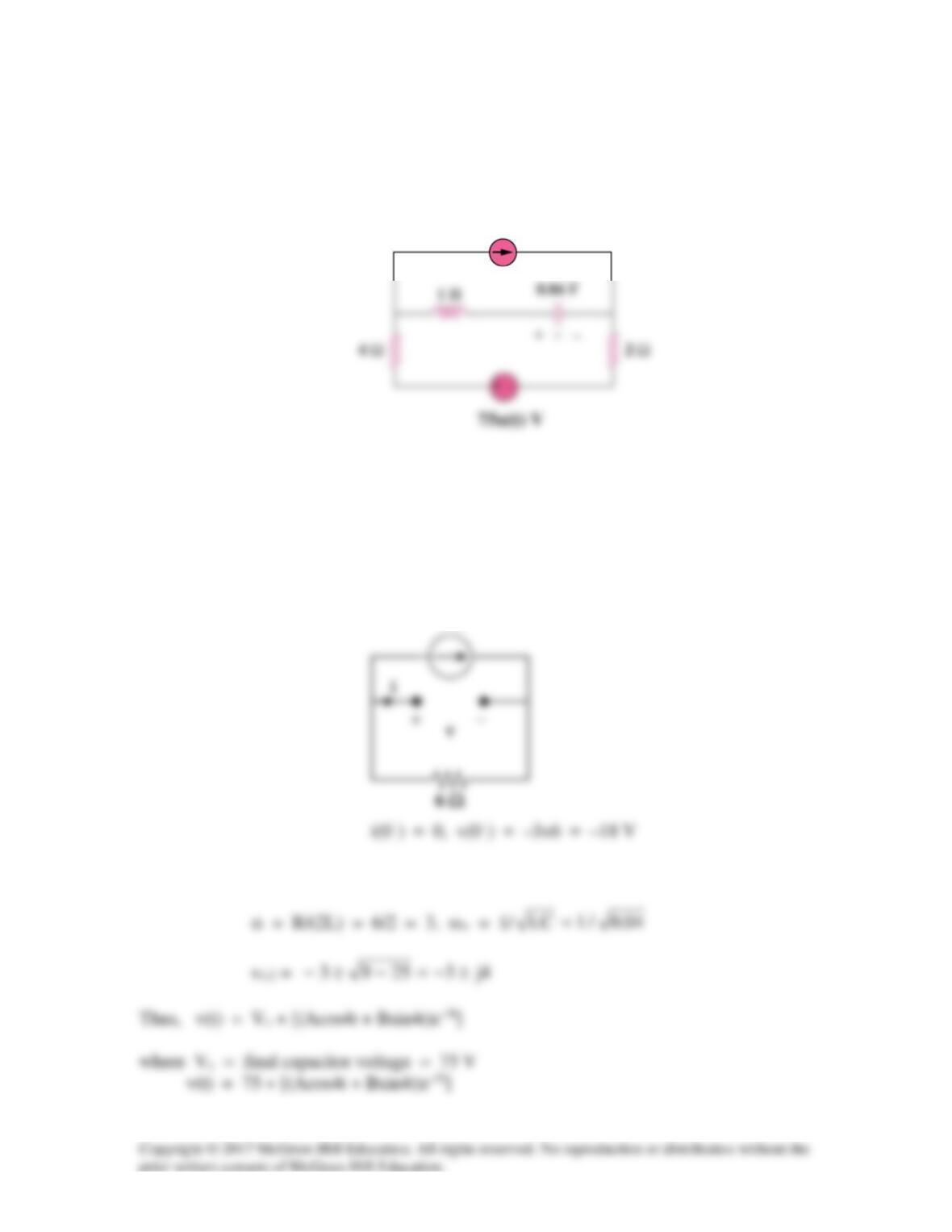
Solution 8.32
For the circuit in Fig. 8.80, find v(t) for t > 0.
Figure 8.80
For Prob. 8.32.
Solution
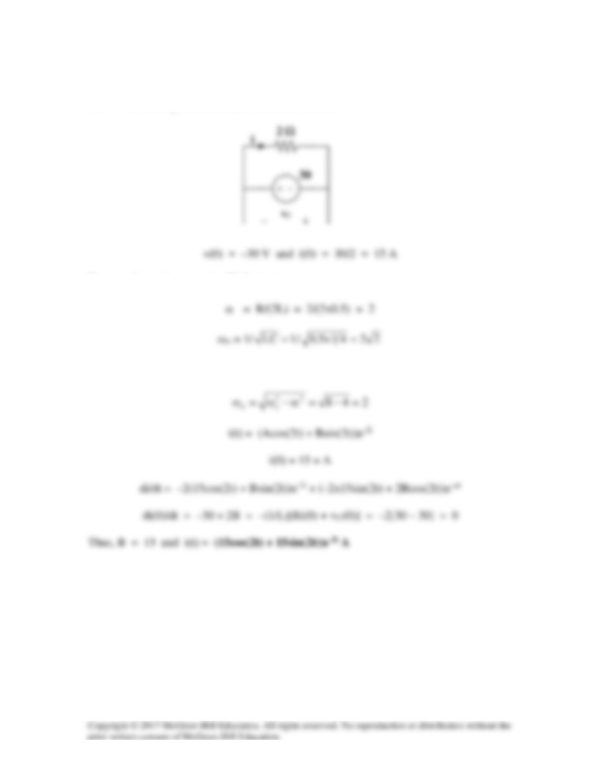
For t = 0–, the equivalent circuit is shown below.
For t > 0, we have a series RLC circuit with a step input.
3 A
3u(–t) A
v(0) = –18 = 75 + A which gives A = –93.
i(0) = 0 = Cdv(0)/dt
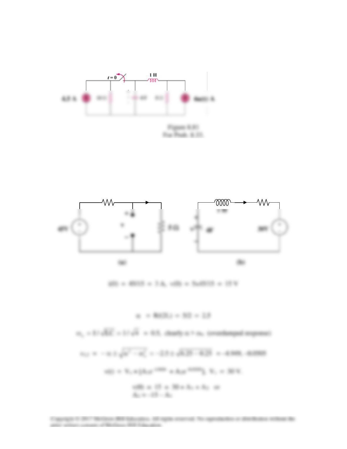
Solution 8.33
Find v(t) for t > 0 in the circuit in Fig. 8.81.
Solution
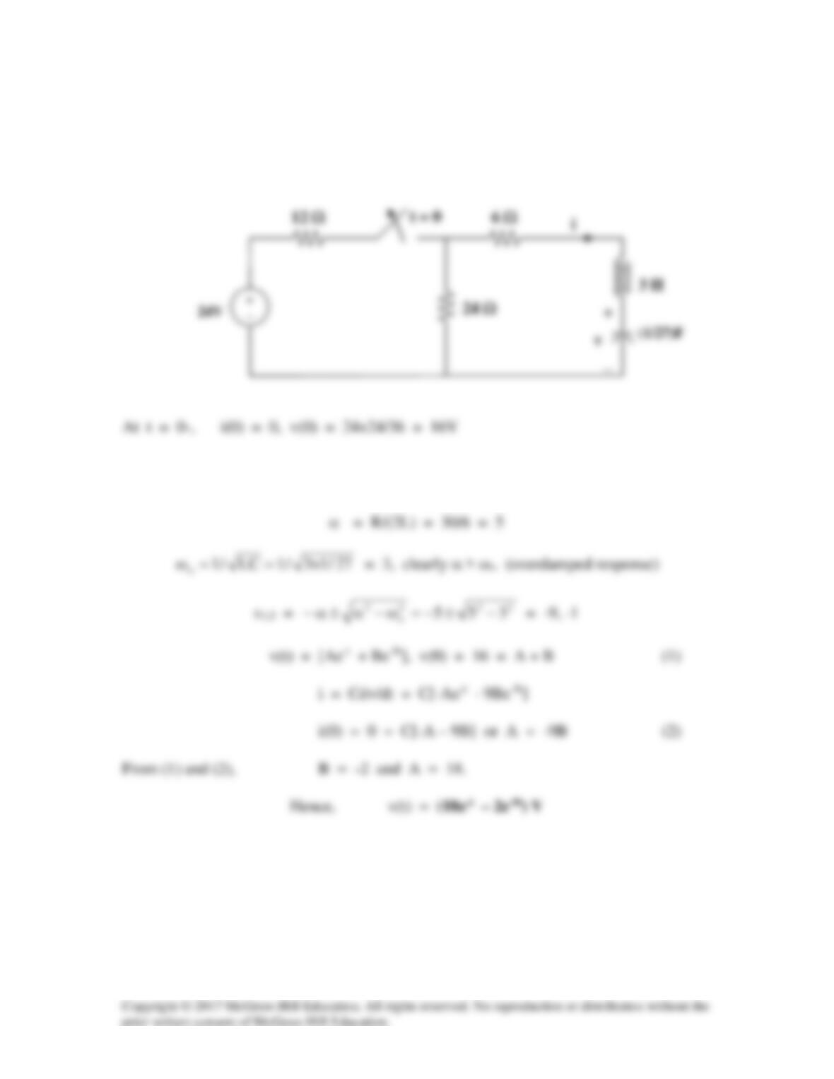
We may transform the current sources to voltage sources. For t = 0–, the equivalent
circuit is shown in Figure (a).
1 H
For t > 0, we have a series RLC circuit, shown in (b).
(1)
10 Ω
i
i
5 Ω
From (1) and (2), –0.75 = –4.949A1 + 0.0505(15 + A1) or