222121o
IzIzV +=
(2)
Substituting (3) and (4) into (1) gives
Solution 19.76
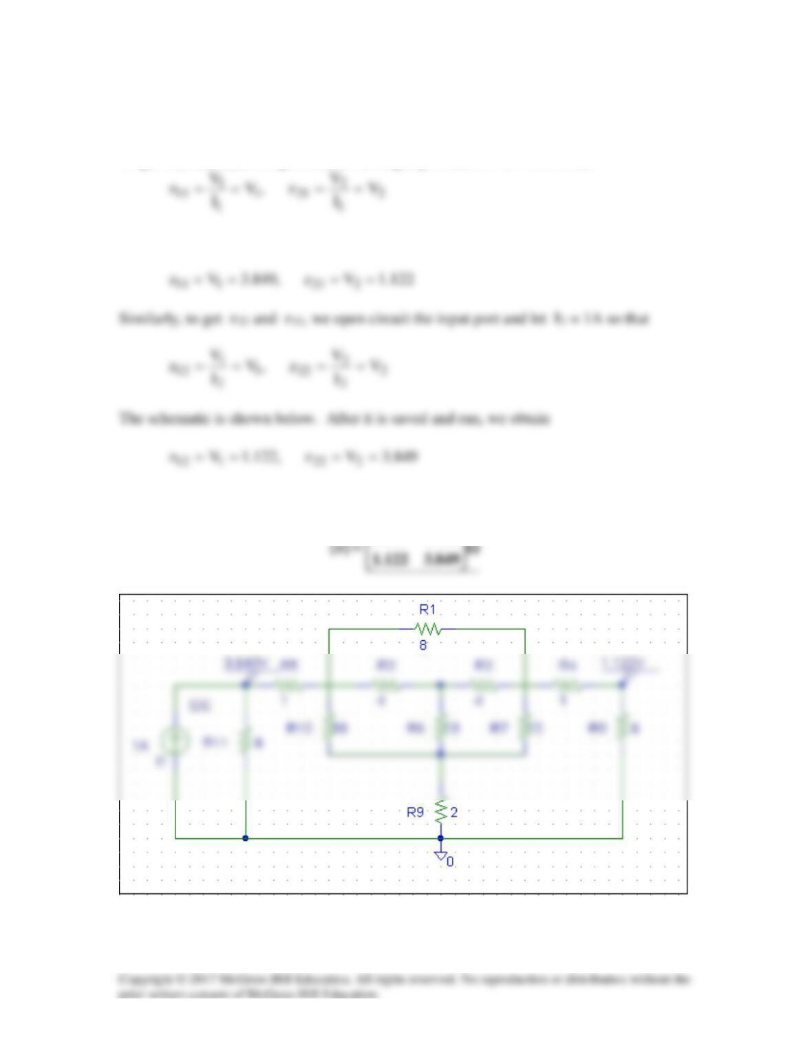
To get z11 and z21, we open circuit the output port and let I1 = 1A so that
The schematic is shown below. After it is saved and run, we obtain
Thus,
122.1949.3
Solution 19.77
We follow Example 19.15 except that this is an AC circuit.
(a) We set V2 = 0 and I1 = 1 A. The schematic is shown below. In the AC Sweep
Box, set Total Pts = 1, Start Freq = 0.1592, and End Freq = 0.1592. After simulation,
the output file includes
FREQ IM(V_PRINT2) IP(V_PRINT2)
From this we obtain
h11 = V1/1 = 0.9488∠–161.6°
(b) In this case, we set I1 = 0 and V2 = 1V. The schematic is shown below. In the
AC Sweep box, we set Total Pts = 1, Start Freq = 0.1592, and End Freq = 0.1592.
After simulation, we obtain an output file which includes
FREQ VM($N_0001) VP($N_0001)
From this,
h12 = V1/1 = 0.3163∠18.42°
Solution 19.78
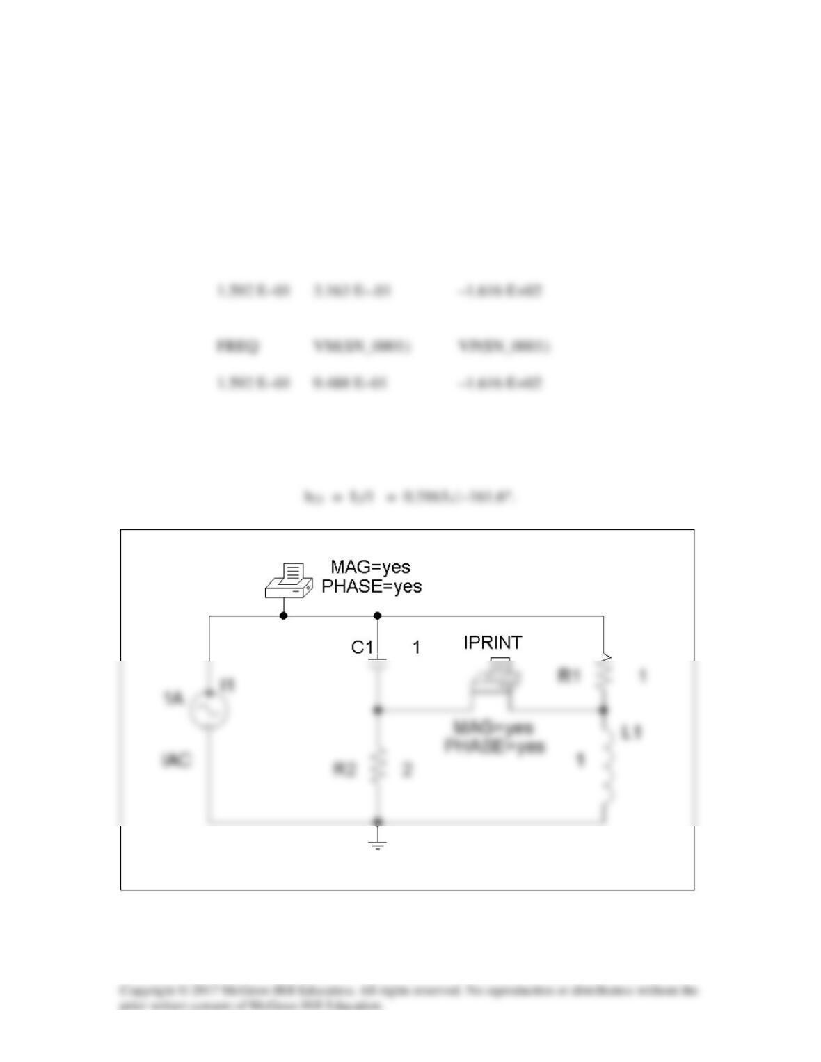
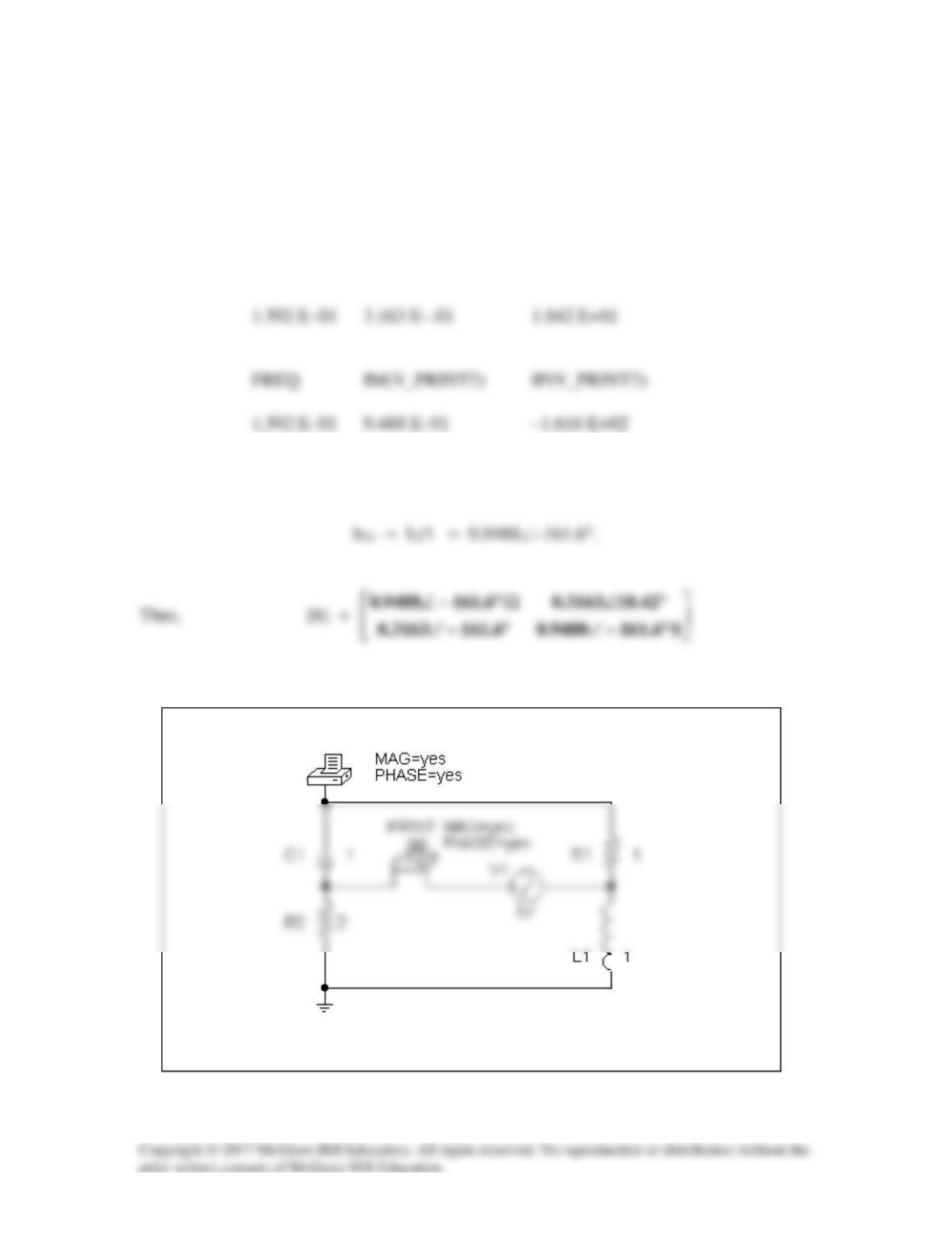
For h11 and h21, short-circuit the output port and let I1 = 1A.
6366.02/ ==
πω
f
. The
schematic is shown below. When it is saved and run, the output file contains the
following:
FREQ IM(V_PRINT1)IP(V_PRINT1)
From the output file, we obtain
so that
For h12 and h22, open-circuit the input port and let V2 = 1V. The schematic is shown
below. When it is saved and run, the output file includes:
From the output file, we obtain
so that
Thus,
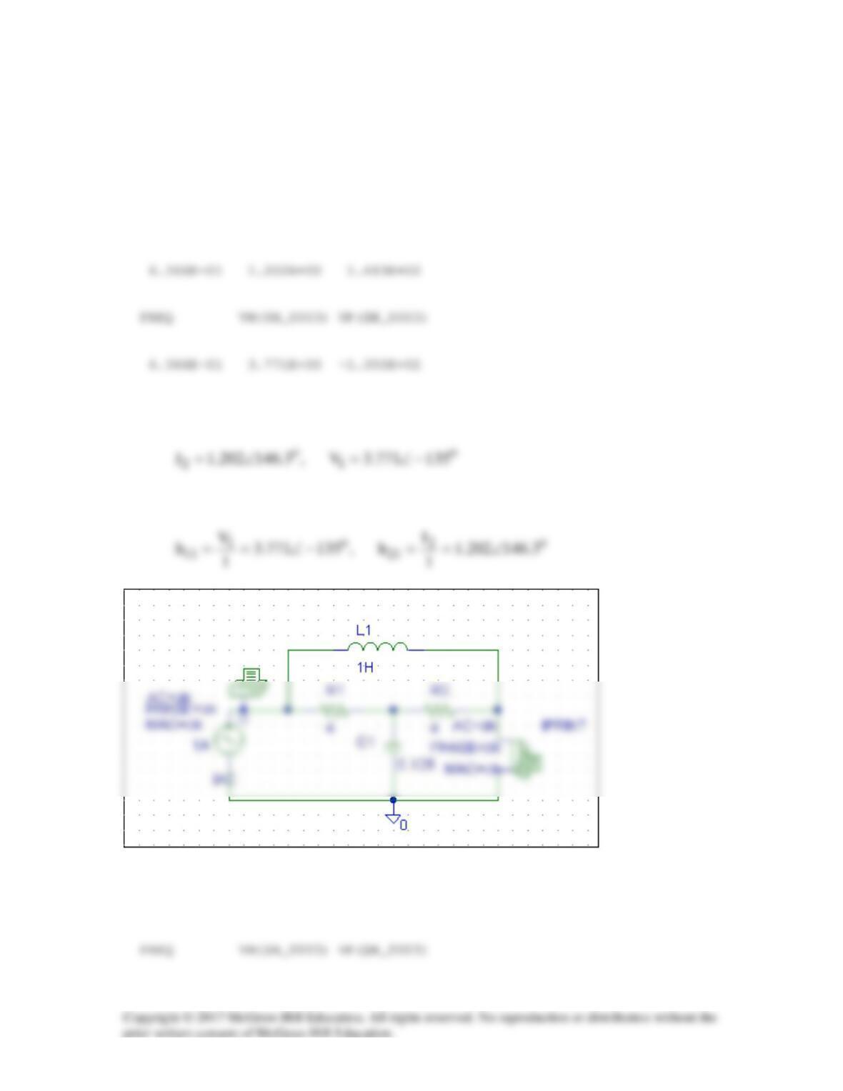
Solution 19.79
We follow Example 19.16.
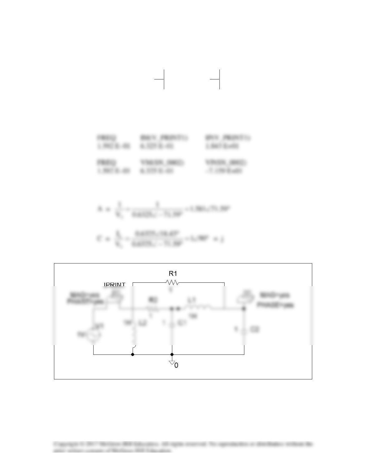
(a) We set I1 = 1 A and open-circuit the output-port so that I2 = 0. The schematic
is shown below with two VPRINT1s to measure V1 and V2. In the AC Sweep box, we
enter Total Pts = 1, Start Freq = 0.3183, and End Freq = 0.3183. After simulation, the
output file includes
FREQ VM(1) VP(1)
From this,
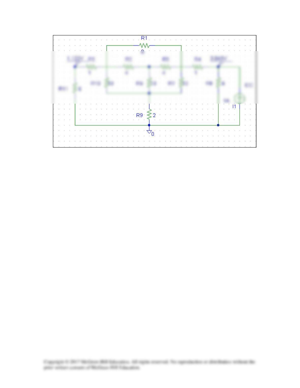
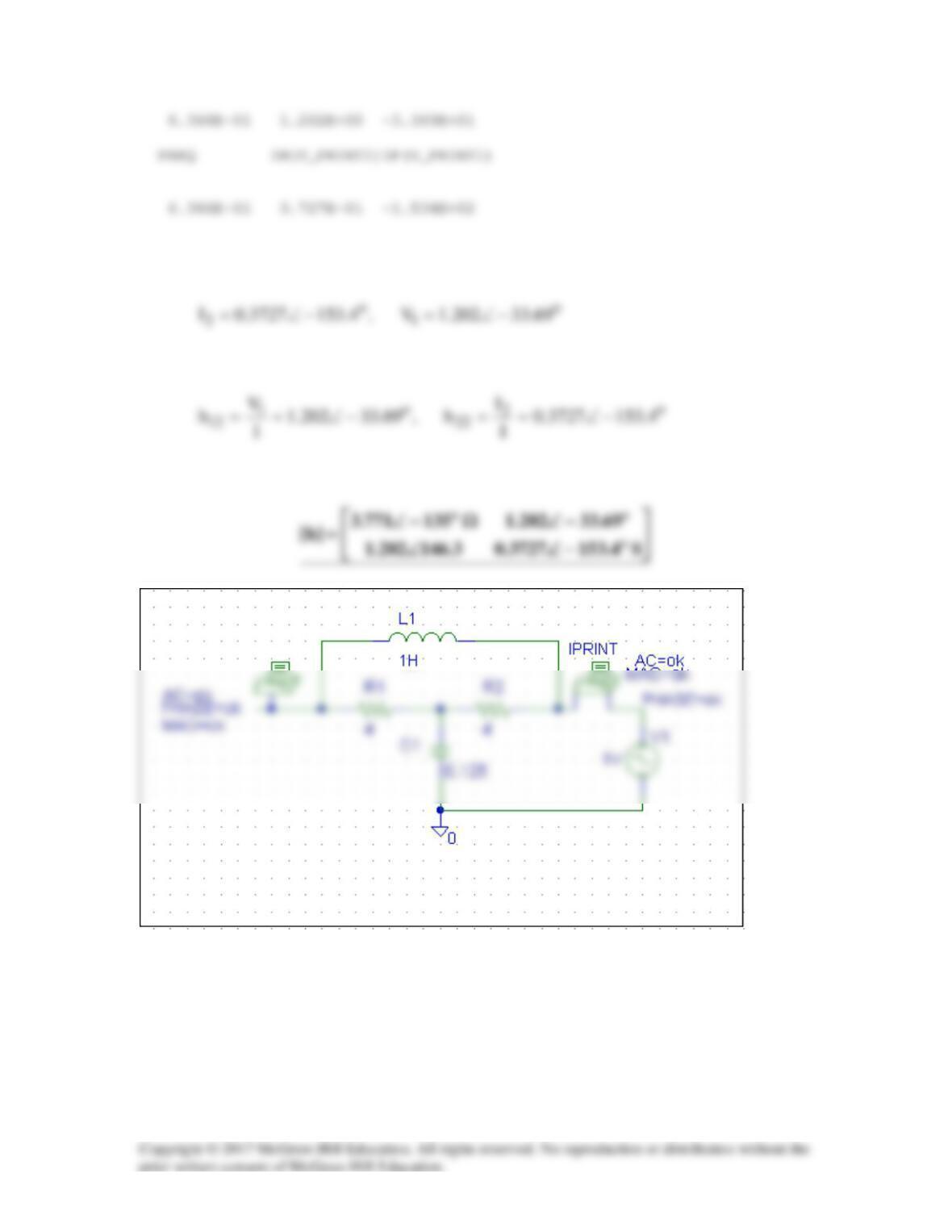
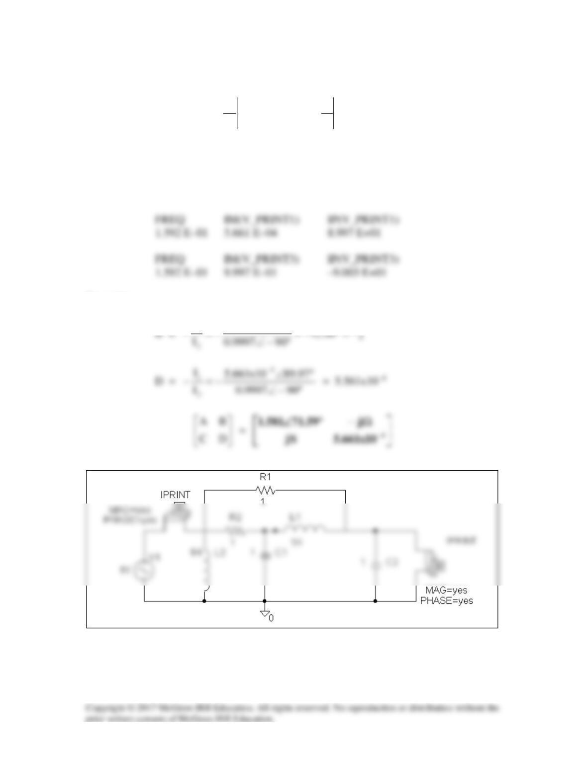
(b) In this case, we let I2 = 1 A and open-circuit the input port. The schematic is
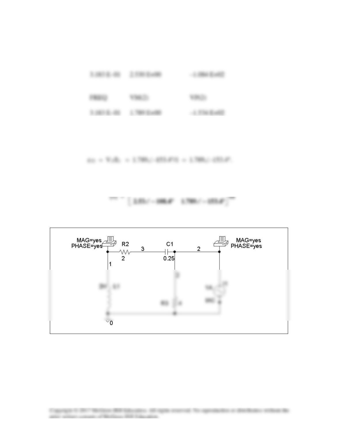
FREQ VM(1) VP(1)
From this,
z12 = V1/I2 = 2.53∠–108.4°/1 = 2.53∠–108..4°
Thus,
°−∠°−∠
4.10853.27.136669.4
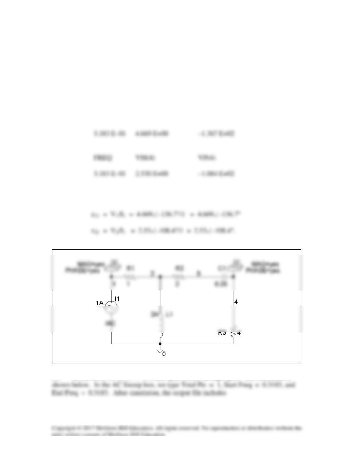
Solution 19.80
Use PSpice or MultiSim to find the z parameters of the circuit in Fig. 19.71. Assume ω =
1 rad/s.
Problem 19.7
Calculate the impedance-parameter equivalent of the circuit in Fig. 19.71.
Figure 19.71
For Prob. 19.7 and 19.80.
Solution
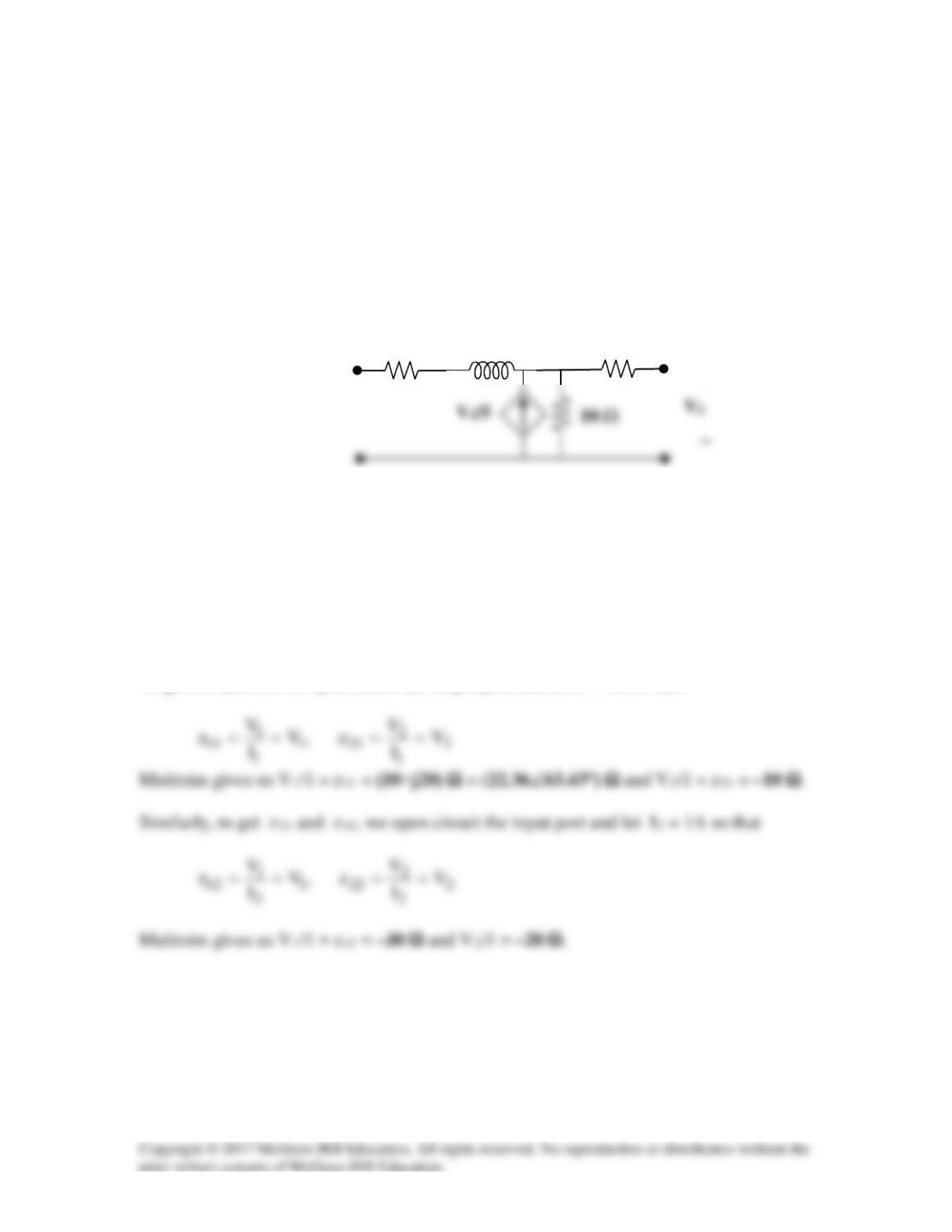
Please note that the Multisim simulation runs better with a higher input frequency, so the
frequency of the input current was scaled by 100 (15.91 Hz), and the inductance was
scaled by 1/100 (0.200 H). So the impedance of the inductor is still j20 ohm.
To get z11 and z21, we open circuit the output port and let I1 = 1A so that
+
20 H
20 Ω
10 Ω
Solution 19.81
(a) We set V1 = 1 and short circuit the output port. The schematic is shown below.
After simulation we obtain
(b) We set V2 = 1 and short-circuit the input port. The schematic is shown below.
Upon simulating the circuit, we obtain
y12 = I1 = –0.5, y22 = I2 = 1.5
Solution 19.82
We follow Example 19.15.
(a) Set V2 = 0 and I1 = 1A. The schematic is shown below. After simulation, we
obtain
(b) Set V1 = 1 V and I1 = 0. The schematic is shown below. After simulation, we
obtain
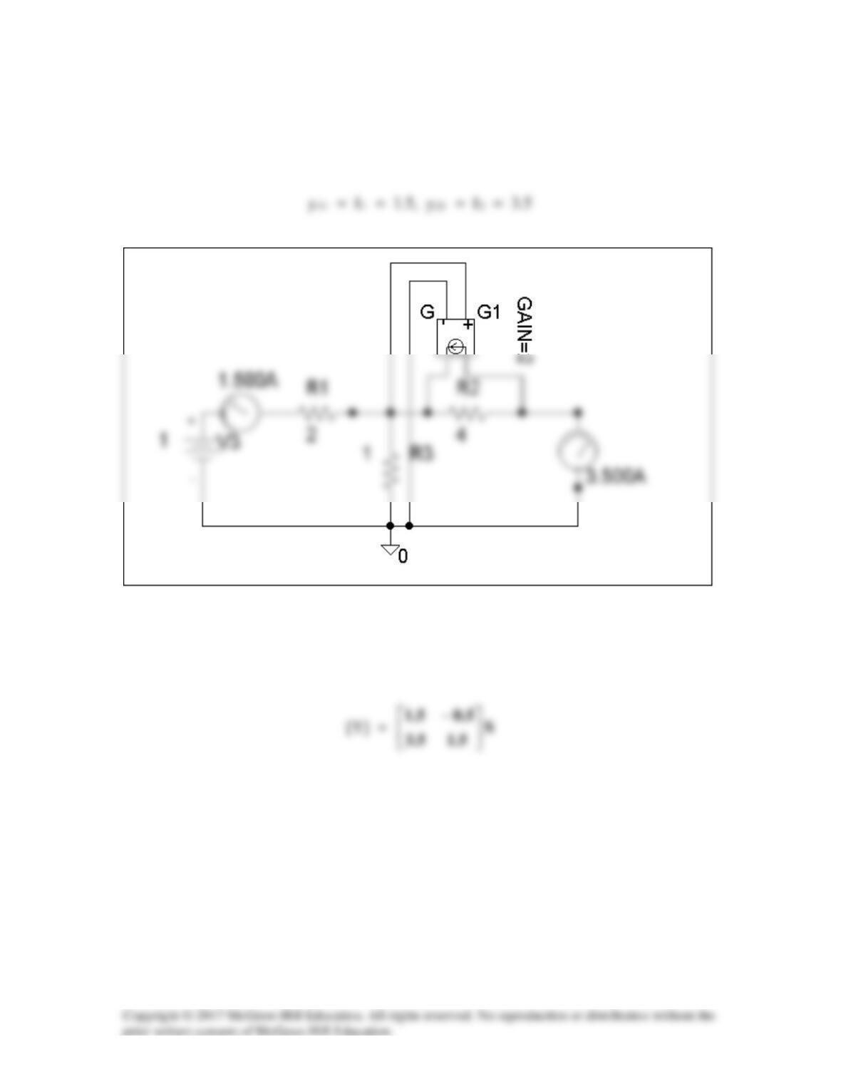
Solution 19.83
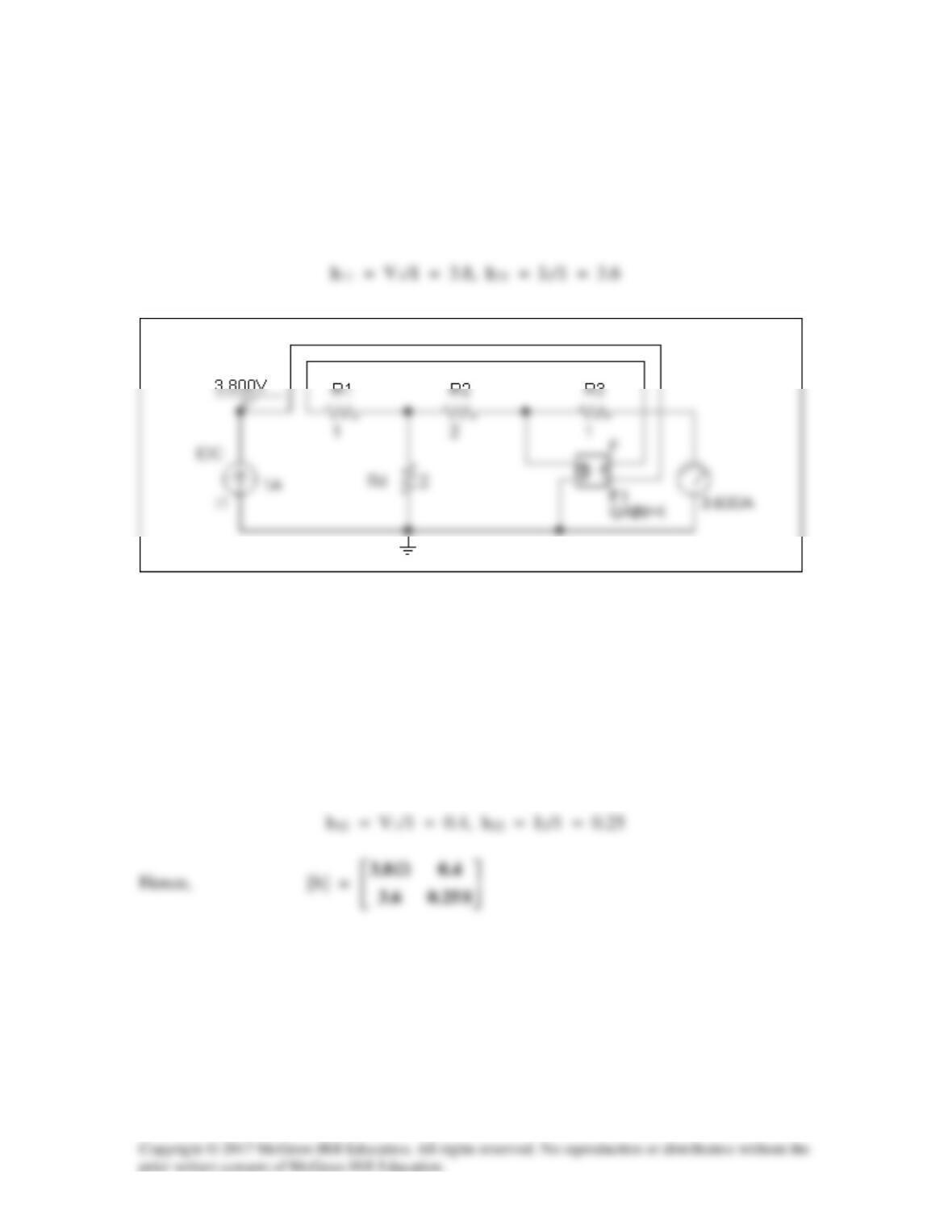
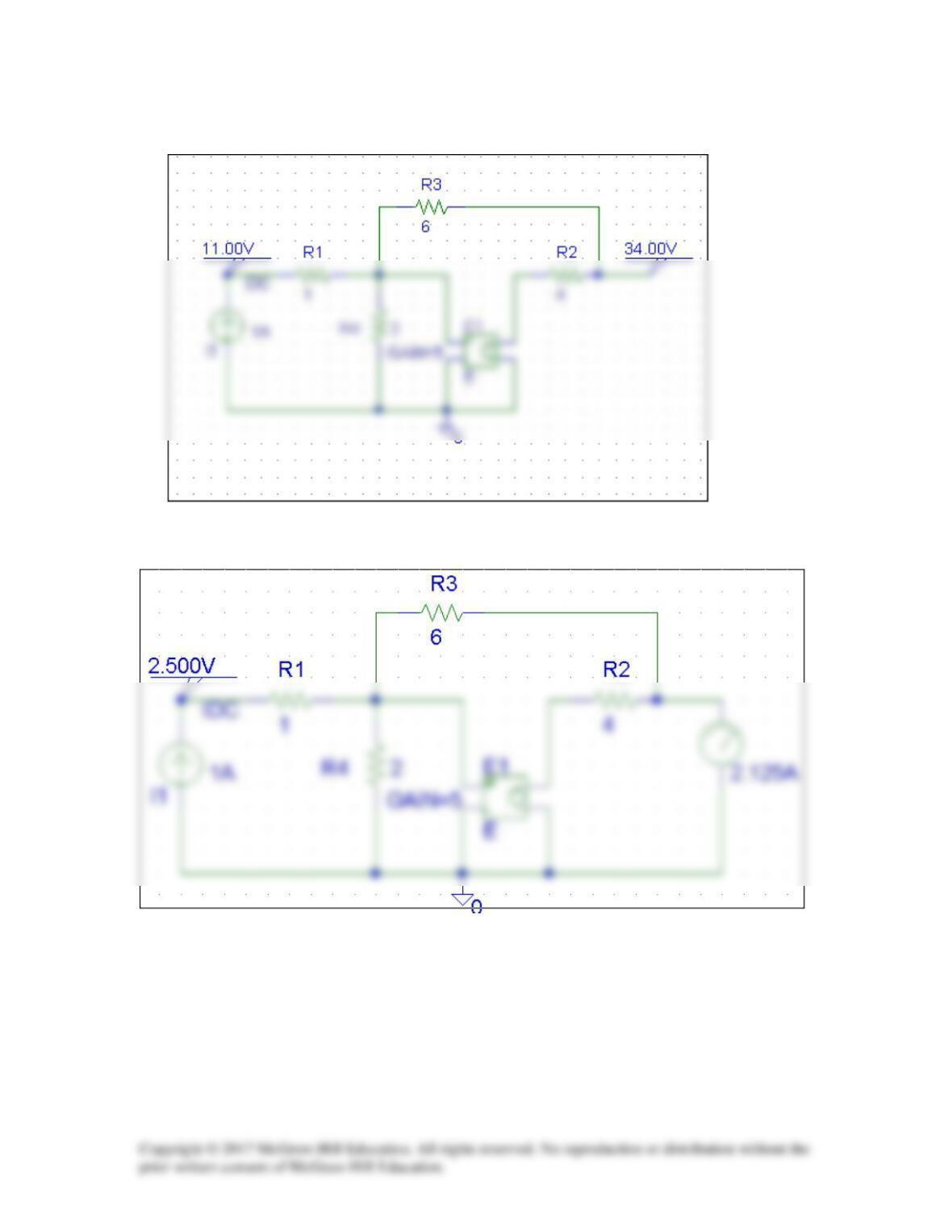
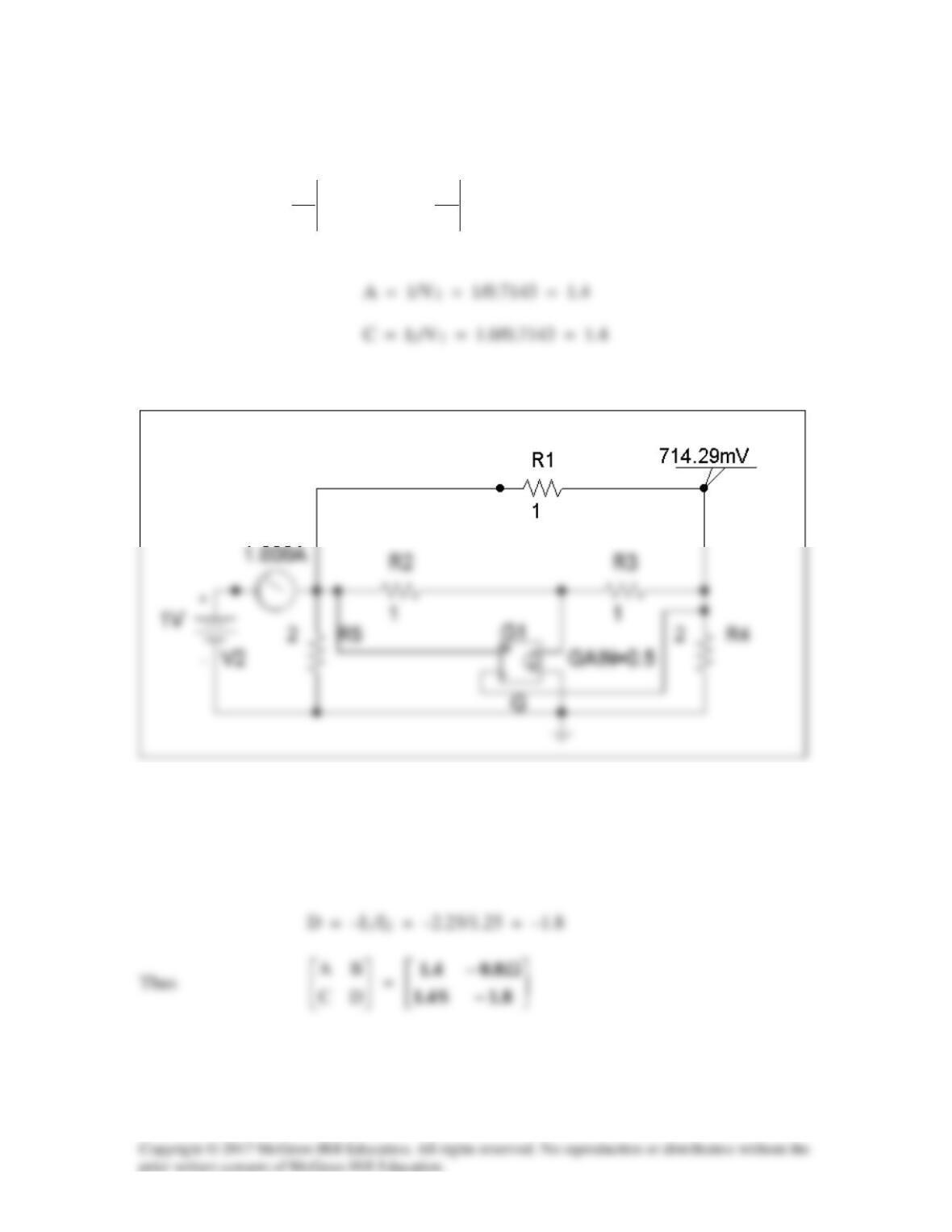
To get A and C, we open-circuit the output and let I1 = 1A. The schematic is shown
below. When the circuit is saved and simulated, we obtain V1 = 11 and V2 = 34.
2
2
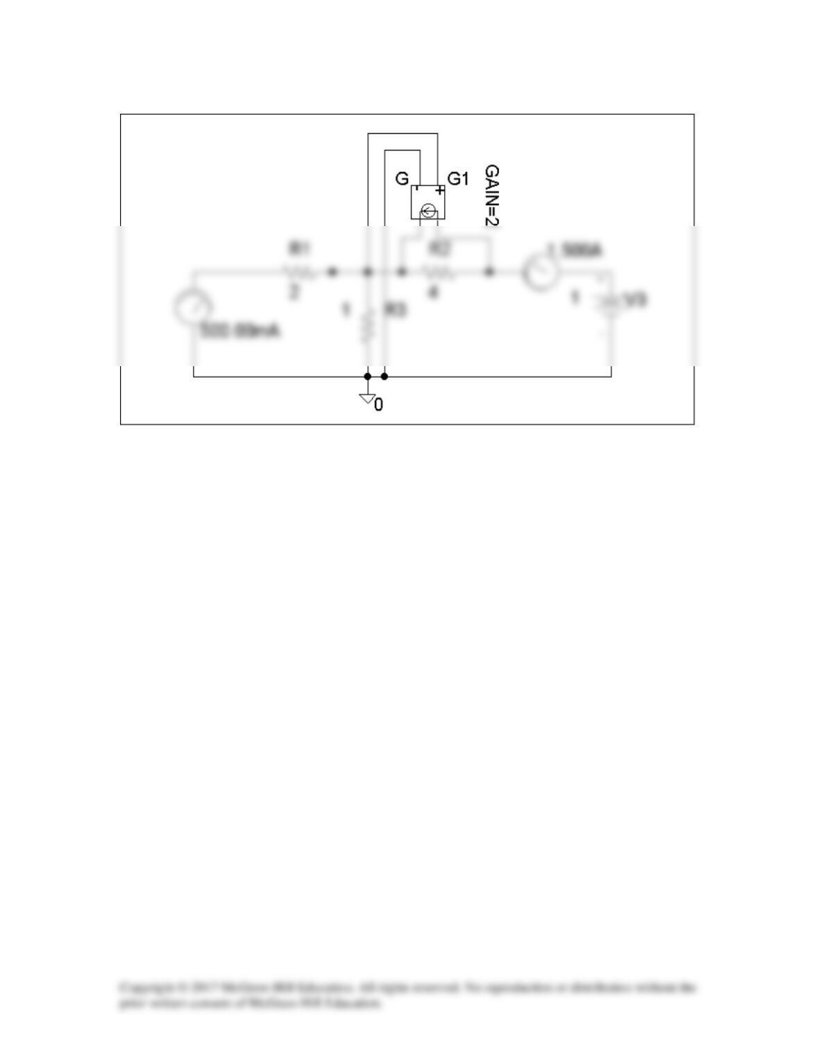
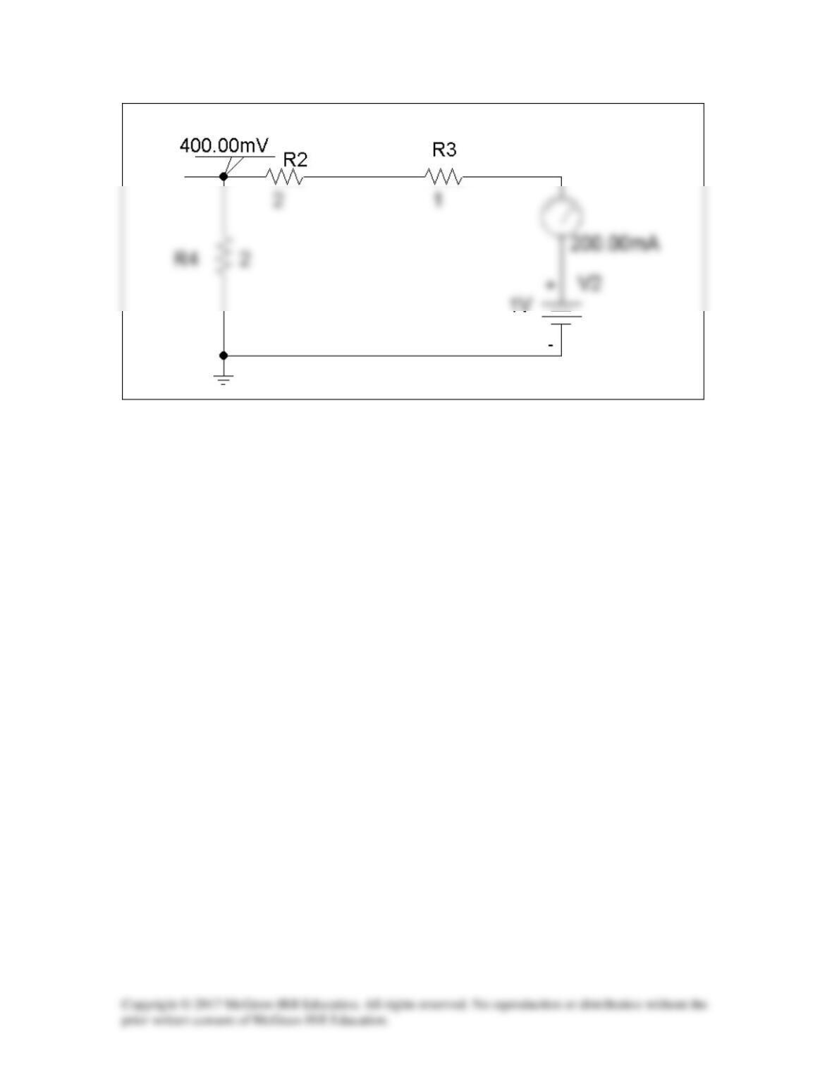
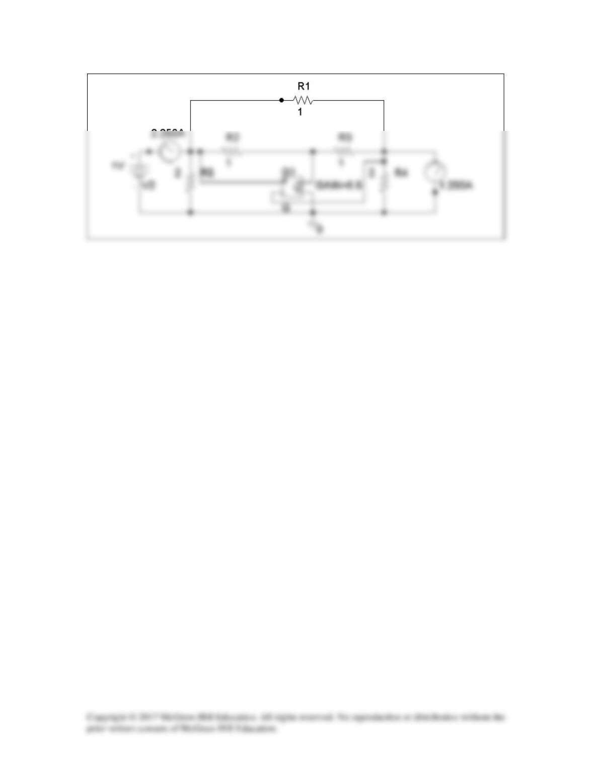
Similarly, to get B and D, we open-circuit the output and let I1 = 1A. The schematic
is shown below. When the circuit is saved and simulated, we obtain V1 = 2.5 and I2
= -2.125.
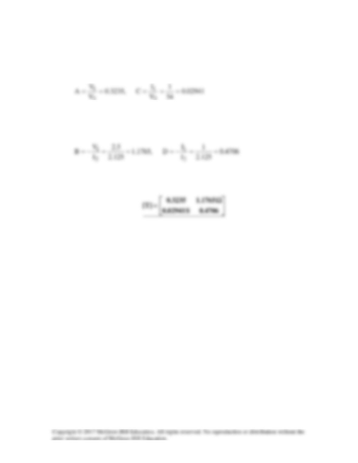
Thus,
Solution 19.84
(a) Since A =
0I
2
1
2
V
V
=
and C =
0I
2
1
2
V
I
=
, we open-circuit the output port and let V1
= 1 V. The schematic is as shown below. After simulation, we obtain
(b) To get B and D, we short-circuit the output port and let V1 = 1. The schematic is
shown below. After simulating the circuit, we obtain
B = –V1/I2 = –1/1.25 = –0.8
Solution 19.85
(a) Since A =
0I
2
1
2
V
V
=
and C =
0I
2
1
2
V
I
=
, we let V1 = 1 V and
open-circuit the output port. The schematic is shown below. In the AC Sweep box, we
set Total Pts = 1, Start Freq = 0.1592, and End Freq = 0.1592. After simulation, we
obtain an output file which includes
From this, we obtain
(b) Similarly, since B =
0V
2
1
2
I
V
=
and D =
0V
2
1
2
I
I
=
−
, we let V1 = 1 V and short-
circuit the output port. The schematic is shown below. Again, we set Total Pts = 1, Start
Freq = 0.1592, and End Freq = 0.1592 in the AC Sweep box. After simulation, we get
an output file which includes the following results:
From this,
1
1