Solution 17.28
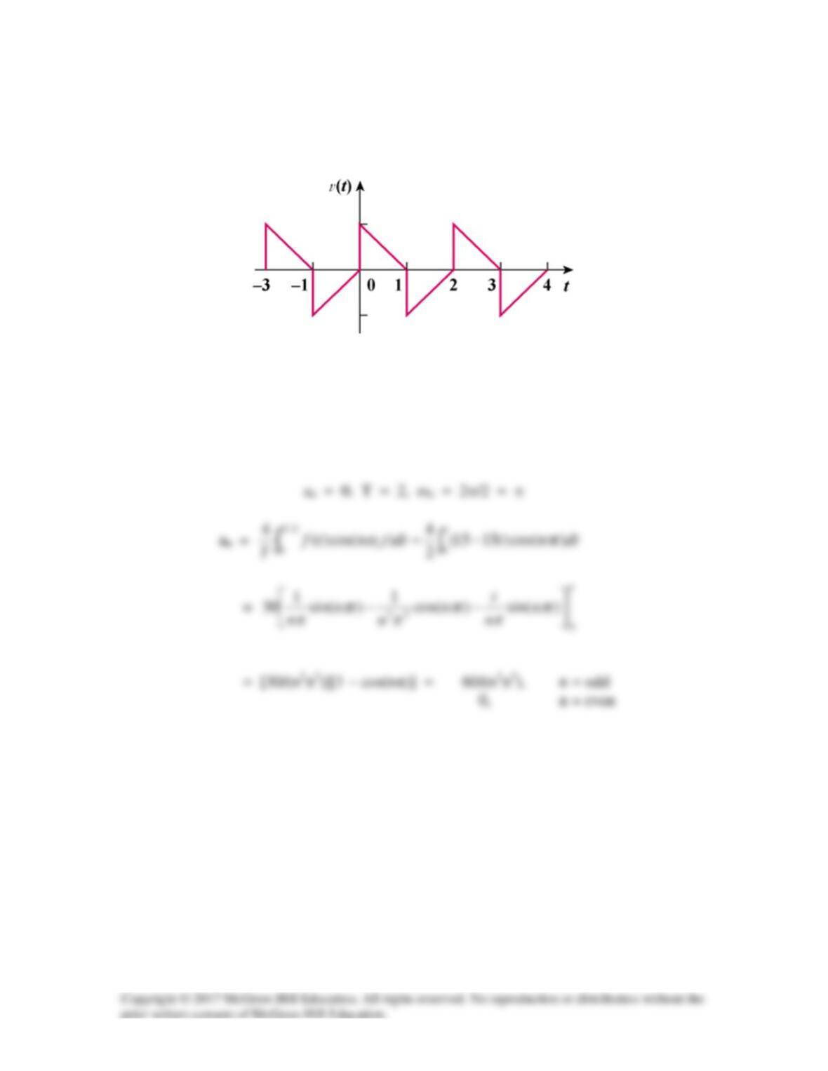
Obtain the trigonometric Fourier series for the voltage waveform shown in Fig. 17.66.
Figure 17.66
For Prob. 17.28.
Solution
This is half–wave symmetric since f(t − T/2) = −f(t).
–15
15
bn =
∫−
1
0)sin()1(30 dttnt
π
Solution 17.29
This function is half-wave symmetric.
Solution 17.30
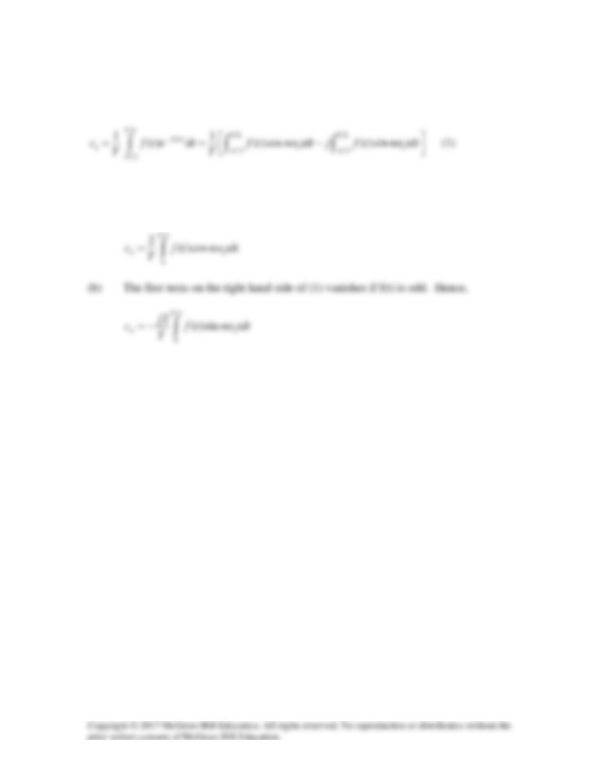
(a) The second term on the right hand side vanishes if f(t) is even. Hence
Solution 17.31
If
oo
/T
2
‘T
2
‘/T‘T),t(f)t(h αω=
α
π
=
π
=ω→α=α=
Solution 17.32
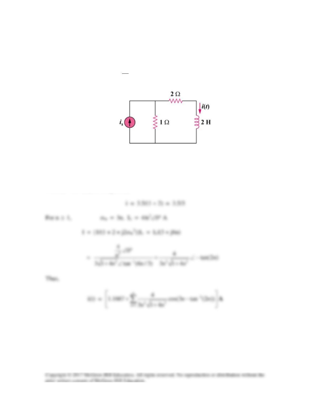
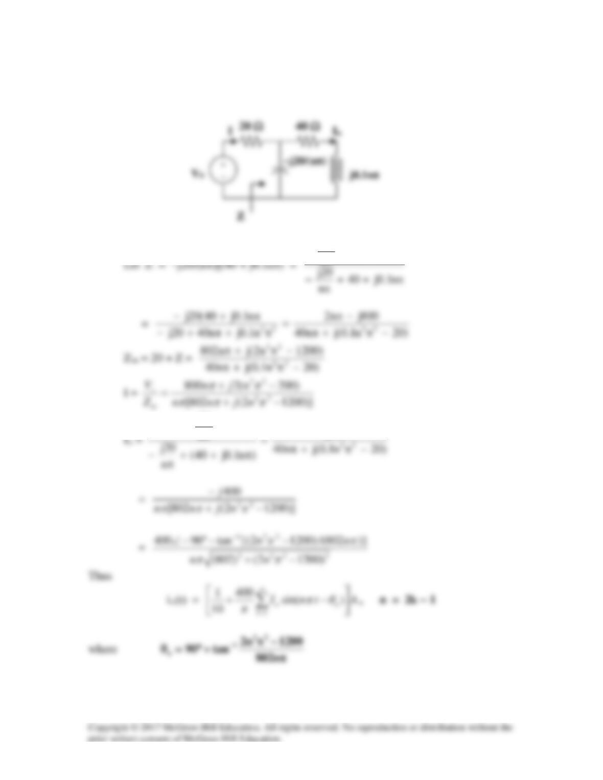
Find i(t) in the circuit of Fig. 17.68 given that
is(t) = 2
n1
4
3.5 cos(3nt) A
n
∞
=
+
∑
Figure 17.68
For Prob. 17.32.
Solution
When is = 3.5 A, (DC component)
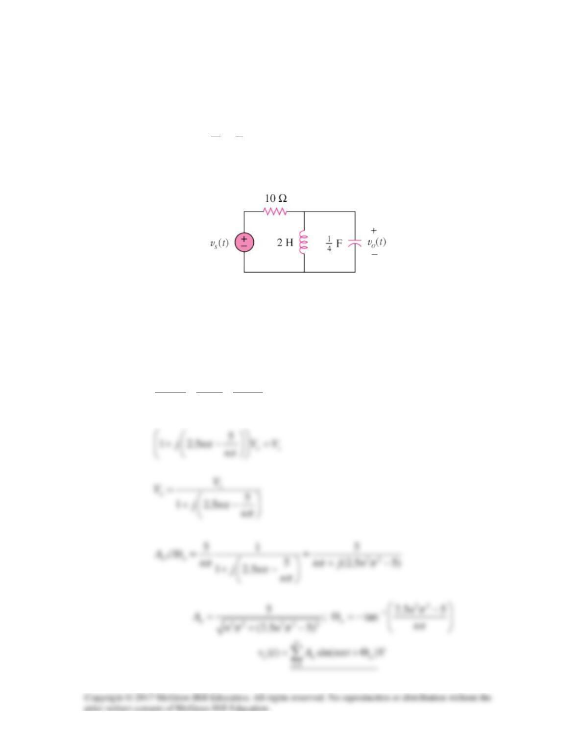
Solution 17.33
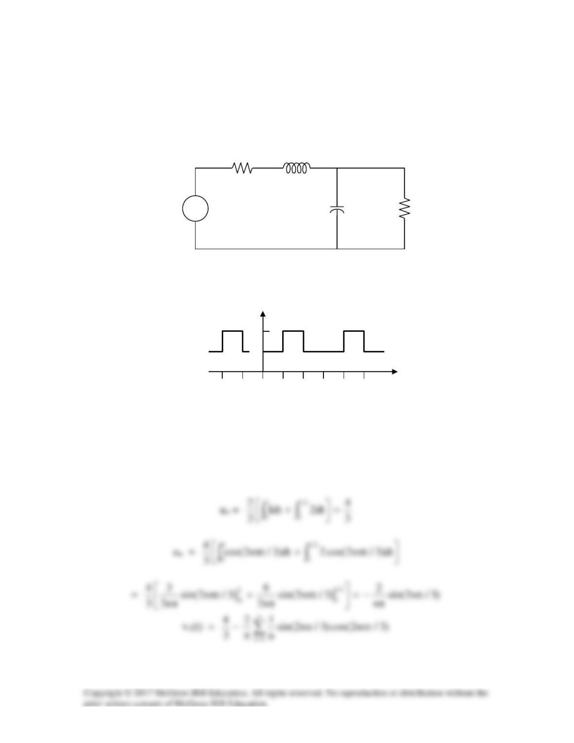
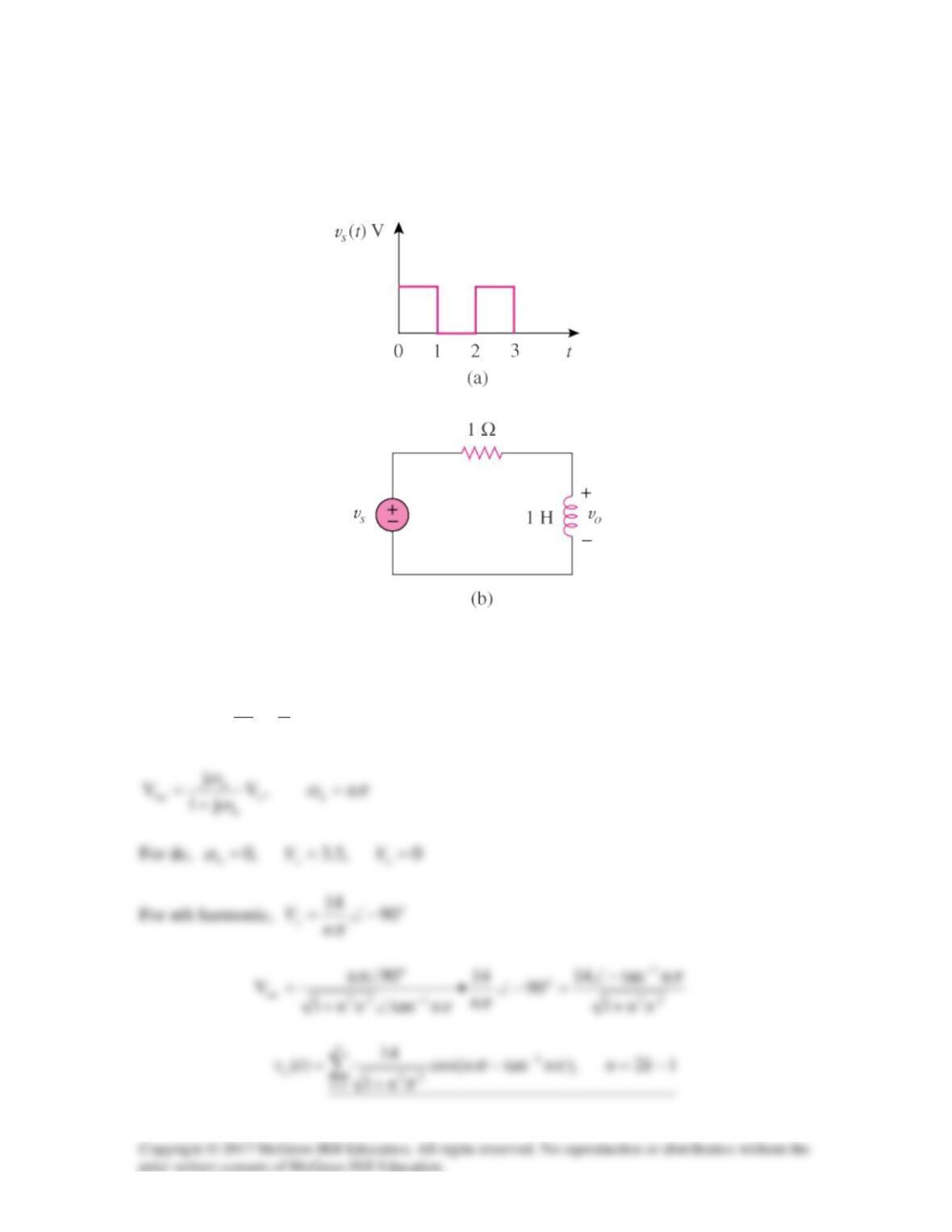
In the circuit shown in Fig. 17.69, the Fourier series expansion of vs(t) is
vs(t) =
1
51
10 sin( )
n
nt
n
π
π
∞
=
+
∑
V
Find vo(t).
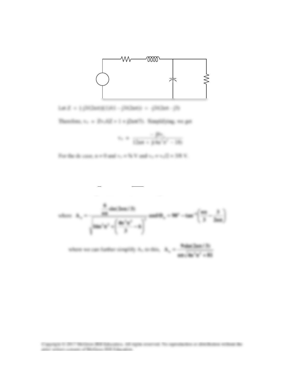
Figure 17.69 For Prob. 17.33.
Solution
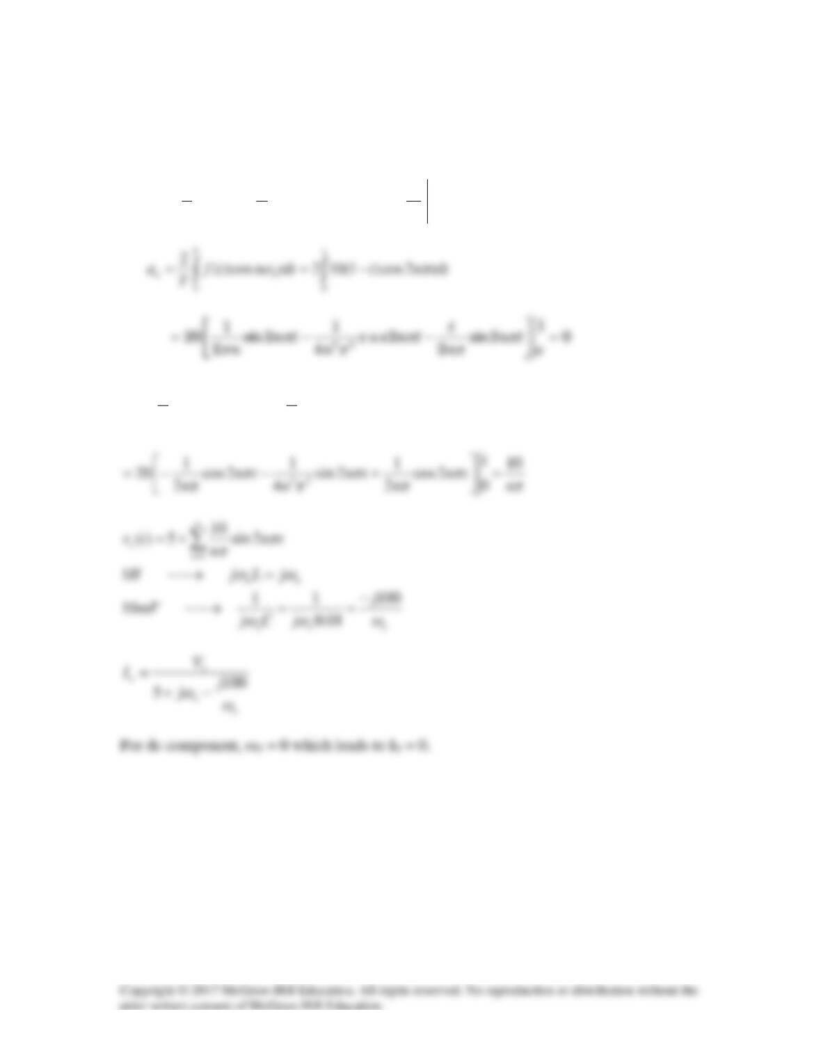
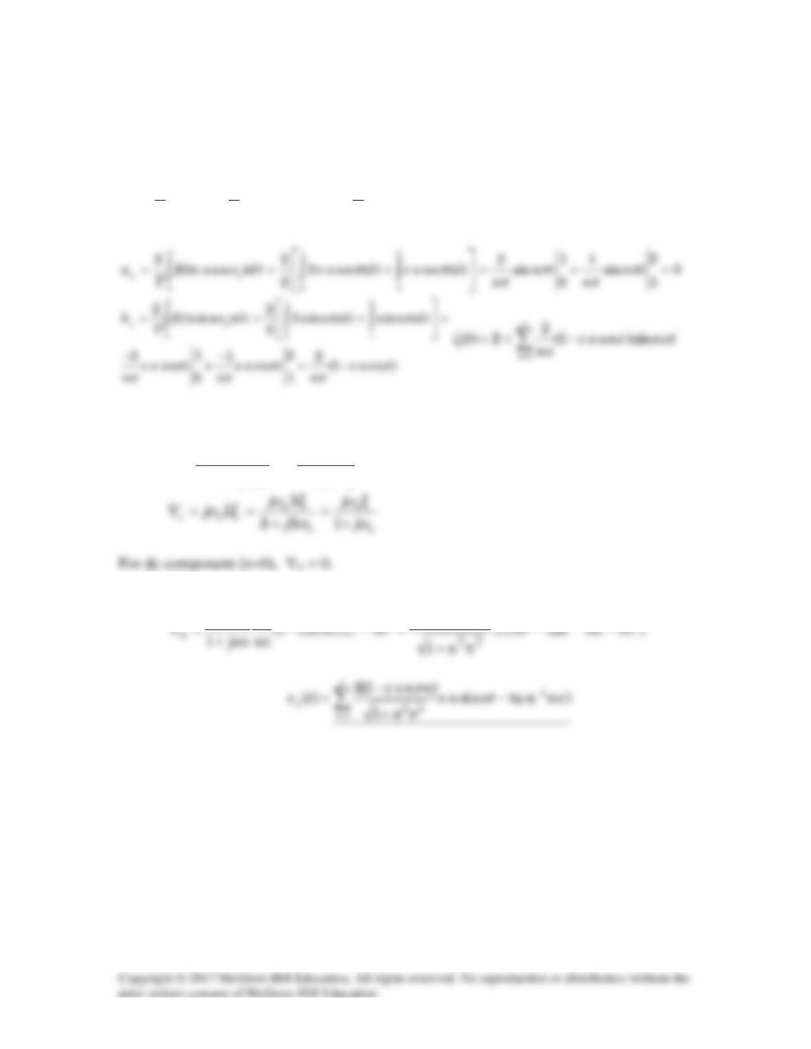
For the DC case, the inductor acts like a short, Vo = 0.
For the AC case, we obtain the following:
0
10 2 4
os o o
V V V jn V
jn
π
π
−++ =
Solution 17.34
Using Fig. 17.70, design a problem to help other students to better understand circuit
responses to a Fourier series.
Although there are many ways to solve this problem, this is an example based on the
same kind of problem asked in the third edition.
Problem
Obtain vo(t) in the network of Fig. 17.70 if
2
1
10
( ) cos 4
n
n
v t nt V
n
π
∞
=
= +
∑
Figure 17.70
Solution
For any n, V = [10/n2]∠(nπ/4), ω = n.
Solution 17.35
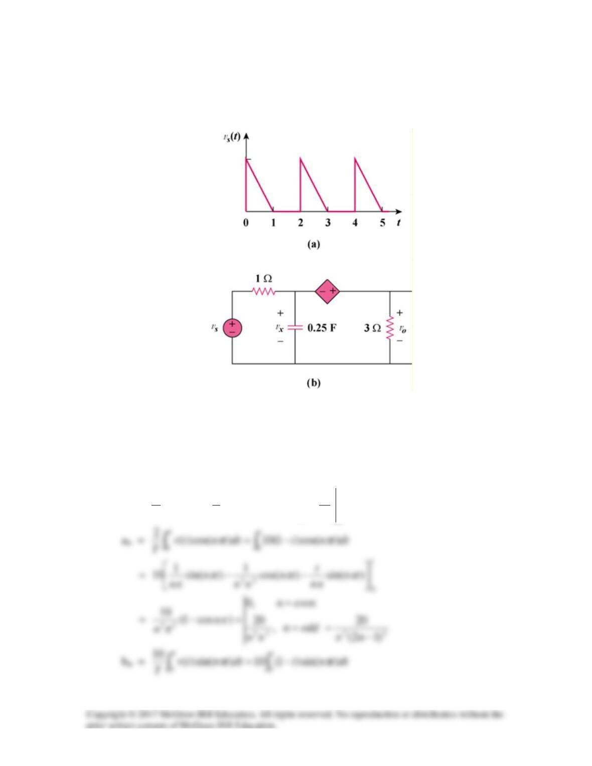
If vs in the circuit of Fig. 17.72 is the same as function f2(t) in Fig. 17.57(b), determine
the dc component and the first three nonzero harmonics of vo(t).
Figure 16.64 For Prob. 16.25
Figure 16.50(b) For Prob. 16.25
The signal is even, hence, bn = 0. In addition, T = 3, ωo = 2π/3.
vs(t) = 1 for all 0 < t < 1
= 2 for all 1 < t < 1.5
vS
+
−
1 Ω
1 Ω
1 H
+
vo
−
1 F
t
5
4
3
2
1
0
-1
-2
2
f2(t)
1
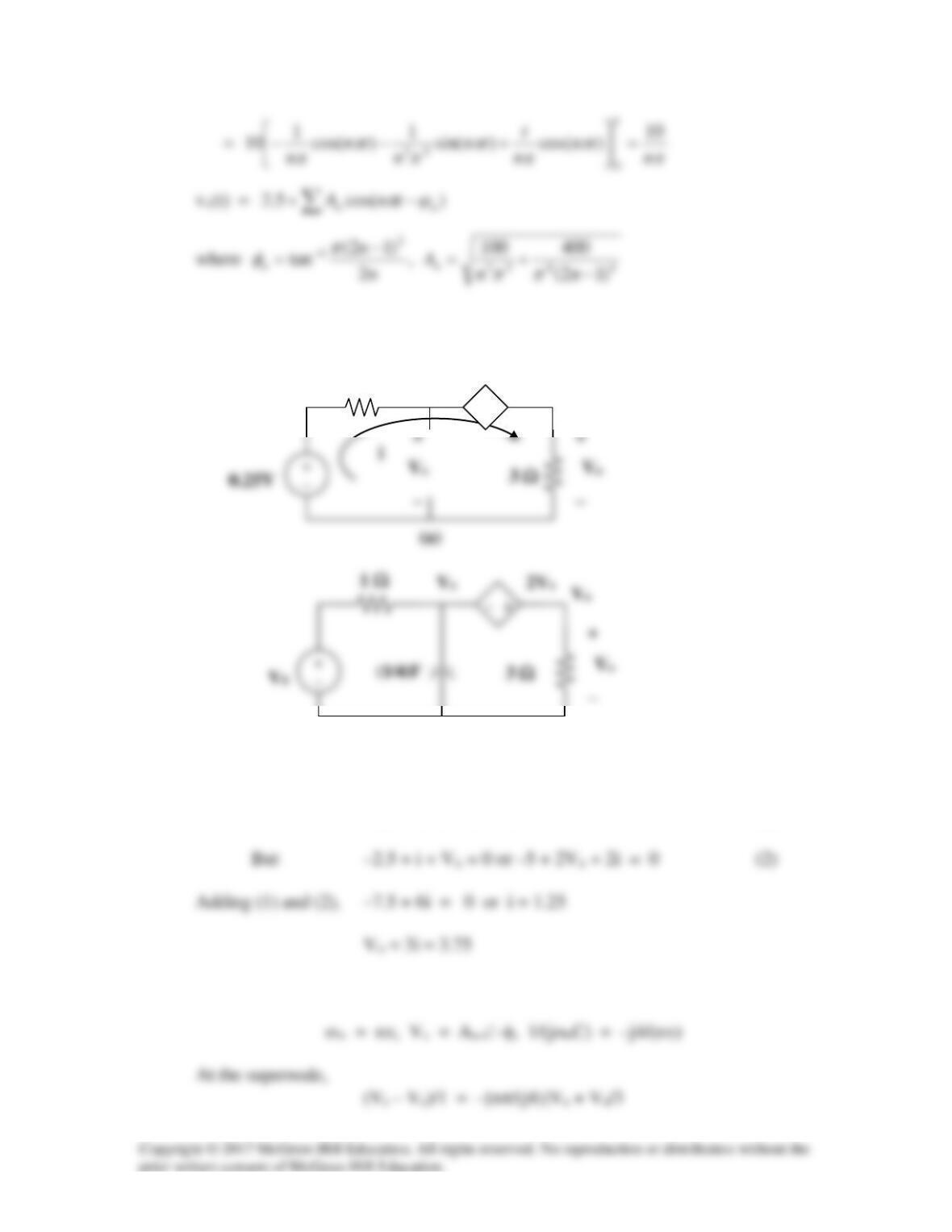
Now consider this circuit,
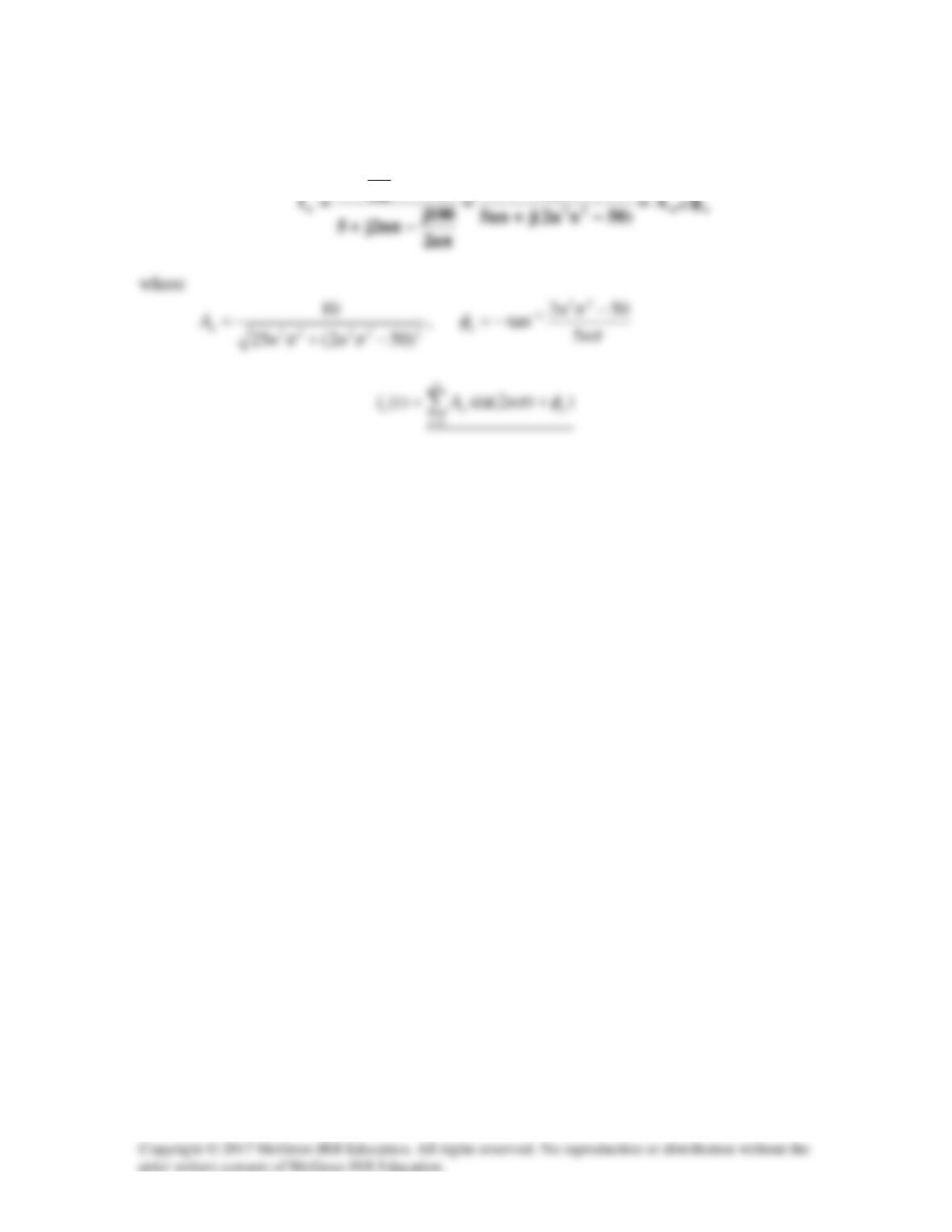
We can now solve for vo(t)
vo(t) =
volts
3
tn2
cosA
8
3
1n
nn
Θ+
π
+∑
∞
=
vS
+
−
1 Ω
1 Ω
j2nπ/3
+
vo
−
–j3/(2nπ)
Solution 17.36
We first find the Fourier series expansion of vs.
1, 2 / 2
o
TT
ωπ π
= = =
12
0
00
0
11
( ) 10(1 ) 10( ) 5
22
1
Tt
a f t dt t tdt t
T
= = −=−=
∫∫
1
00
22
( )sin 10(1 ) sin
2
T
no o
b f t n td t t t n td t
T
ωω
= = −
∫∫
For the nth harmonic,
10
0
n
10
°∠
π
Solution 17.37
We first need to express is in Fourier series.
2, 2 /
o
TT
ωπ π
= = =
12
0 01
11 1
( ) 3 1 ( 3 1) 2
22
T
o
a f t dt dt dt
T
= = + = +=
∫ ∫∫
By current division,
1
12 3 3
s
o s
nn
I
II
jL j
ωω
= =
++ +
For the nth harmonic,
)ncos1(2
2
jn
1
π−
π
Solution 17.38
If the square wave shown in Fig. 17.74(a) is applied to the circuit in Fig. 17.74(b), find
the Fourier series for vo(t).
Figure 17.74 For Prob. 17.38.
Solution
∑
∞
=
+=+=
1
12,sin
114
5.3)(
k
s
kntn
n
tv
π
π
7
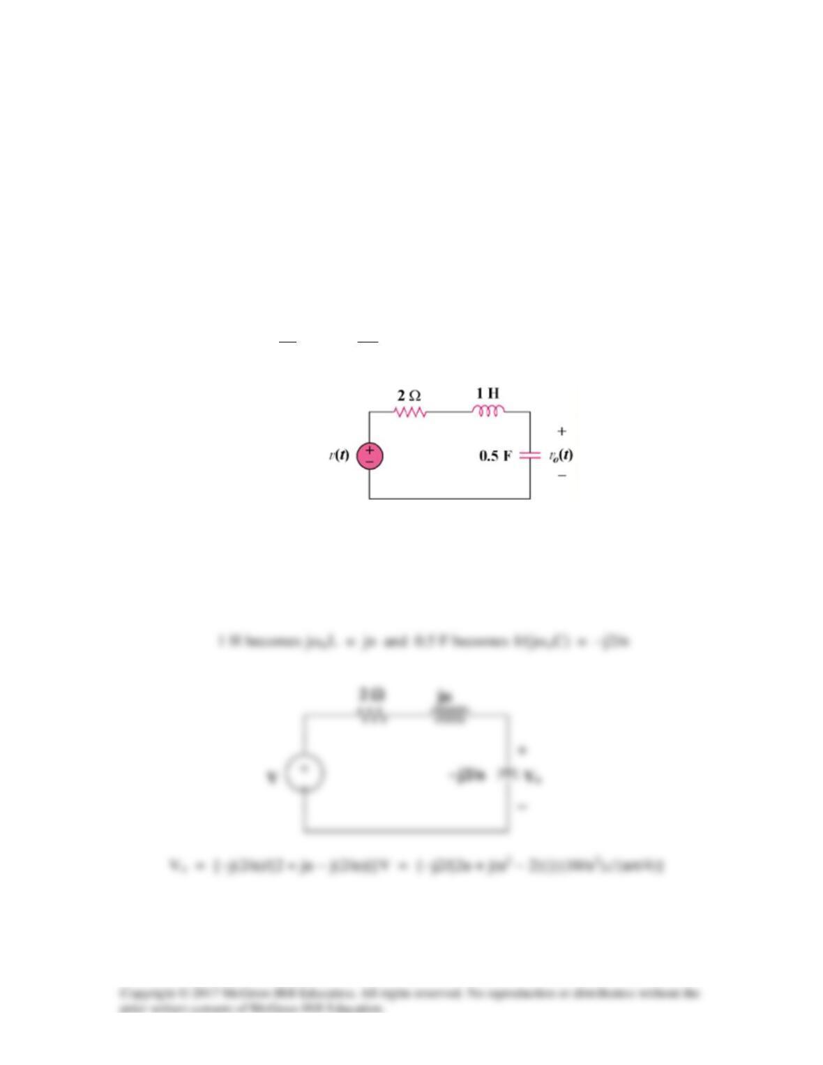
Solution 17.39
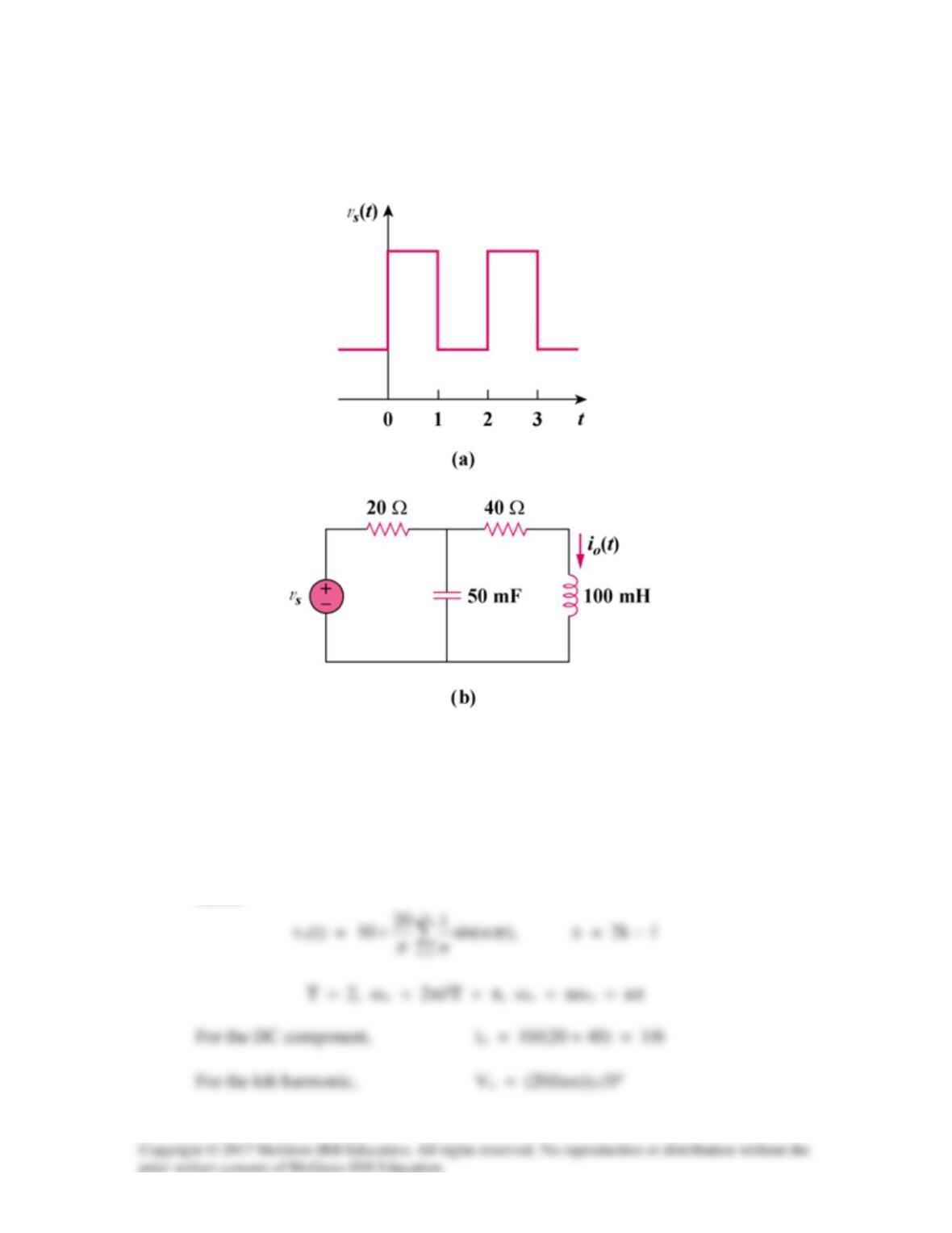
If the periodic voltage in Fig. 17.75(a) is applied to the circuit in Fig. 17.75(b), find io(t).
Figure 17.75 For Prob. 17.39.
Solution
Comparing vs(t) with f(t) in Figure 15.1, vs is shifted by 2.5 and the magnitude is 5 times
that of f(t).
Hence
5
15
100 mH becomes jωnL = jnπx0.1 = j0.1nπ
50 mF becomes 1/(jωnC) = −j20/(nπ)
π+
π
−
)n1.0j40(
n
20j
I20j
I
n
20j
−
π
−
Solution 17.40
The signal in Fig. 17.76(a) is applied to the circuit in Fig. 17.76(b). Find vo(t).
Figure 17.76
For Prob. 17.40.
Solution
T = 2, ωo = 2π/T = π
ao =
5.2
2
5)1010(
2
1
)(
11
0
2
1
00 =
−=−=
∫∫
t
tdttdttv
T
T
10
2vx
For the DC component, vs = 2.5. As shown in Figure (a), the capacitor acts like
an open circuit.
1 Ω
− +
Vx
2Vx
Vo
(a)
Applying KVL to the circuit in Figure (a) gives
–2.5 – 2Vx + 4i = 0 (1)
For the nth harmonic, we consider the circuit in Figure (b).
(b)
1 Ω
− +
Vx
2Vx
Vo