Solution 10.71
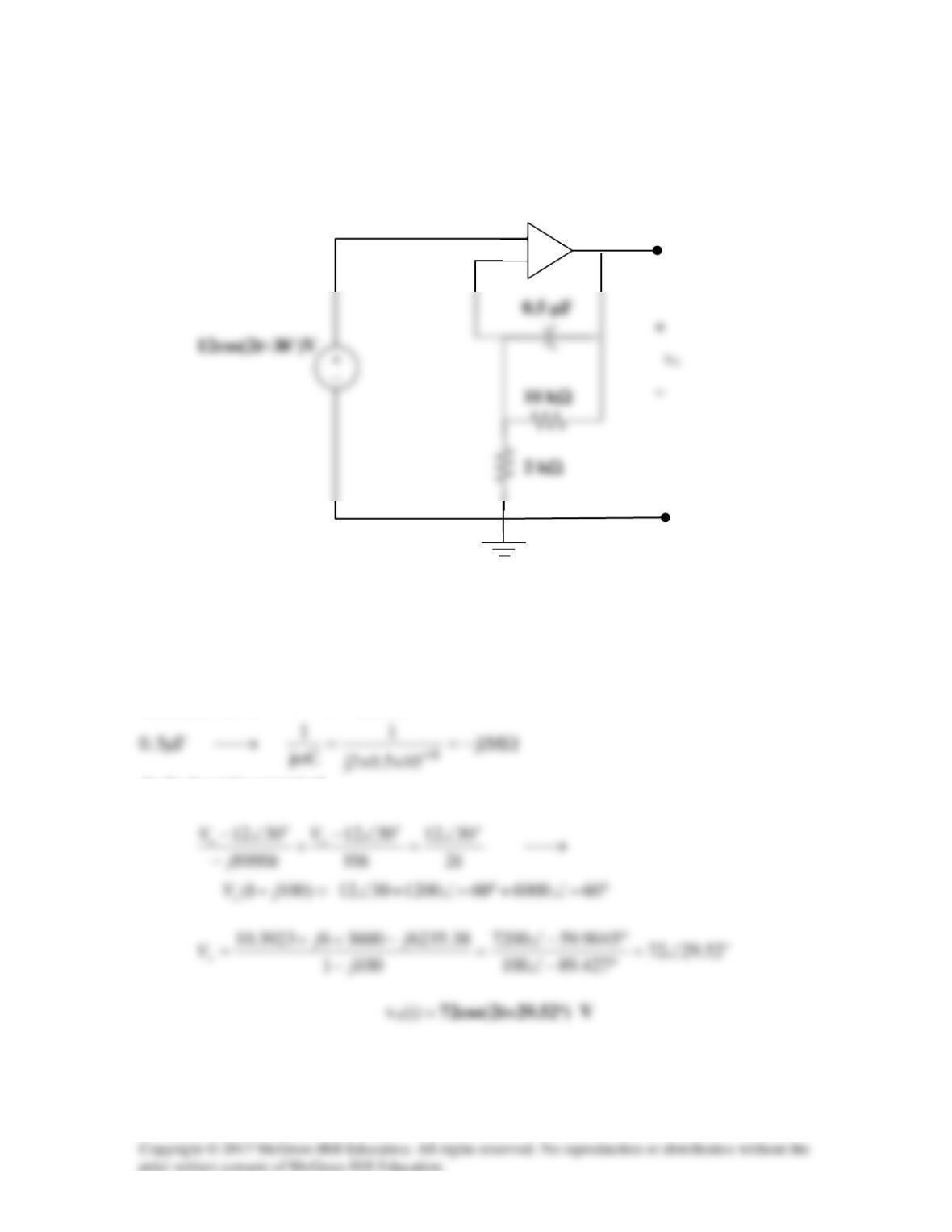
Find vo in the op amp circuit shown in Fig. 114.
Figure 10.114
For Prob. 10.71.
Solution
oo
t3012)302cos(12 ∠→+
At the inverting terminal,
+
−
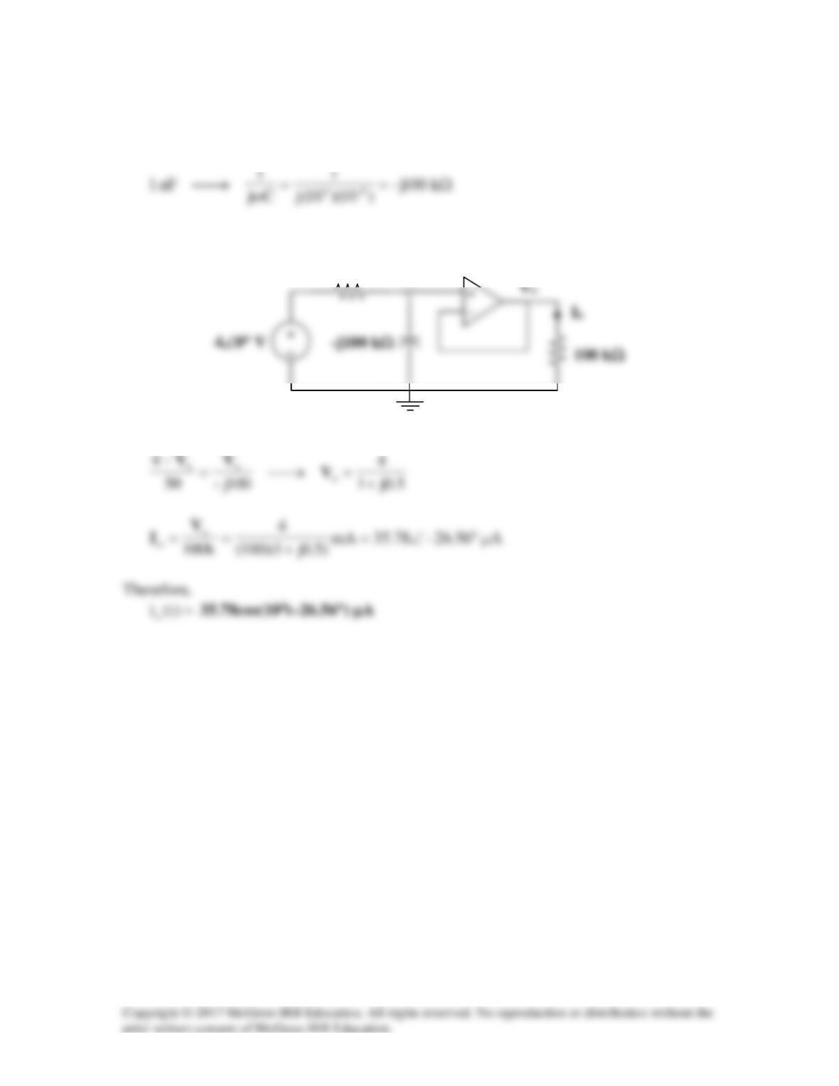
Solution 10.72
44 10,04)t10cos(4=ω°∠→
Consider the circuit as shown below.
At the noninverting node,
Vo
50 kΩ
Vo
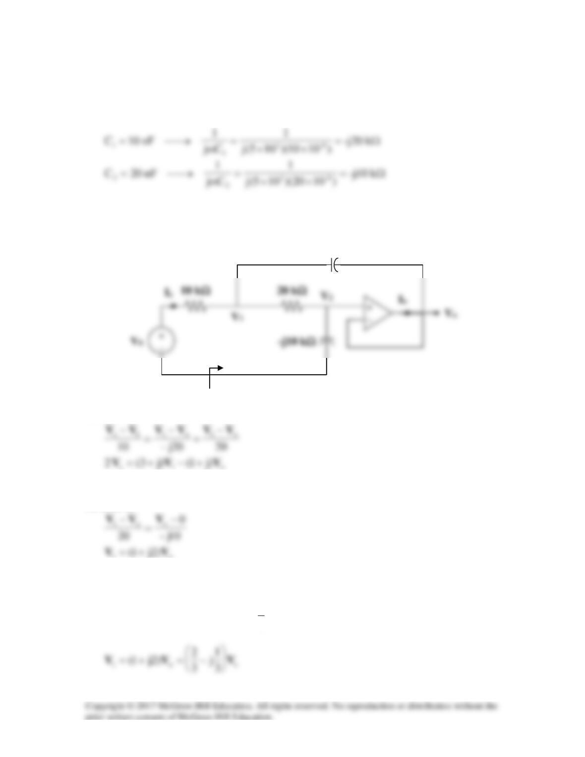
Solution 10.73
As a voltage follower, o2
VV =
Consider the circuit in the frequency domain as shown below.
At node 1,
(1)
At node 2,
o1 )2j1( VV +=
(2)
Substituting (2) into (1) gives
os
6j2 VV =
or
so 3
1
-j VV =
-j20 kΩ
Zin
s
1s
sk10
)j1)(31(
k10 V
VV
I+
=
−
=
Solution 10.74
1
1i
Cj
1
Rω
+=Z
,
2
2f
Cj
1
Rω
+=Z
=
v
A
As
∞→ω
,
=
v
A
–
1
2
R
R
=
v
A
=
v
A
Solution 10.75
3
102 ×=ω
Consider the circuit shown below.
Let Vs = 10V.
At node 2,
At node b,
Substituting (3) and (4) into (1),
100 kΩ
Solution 10.76
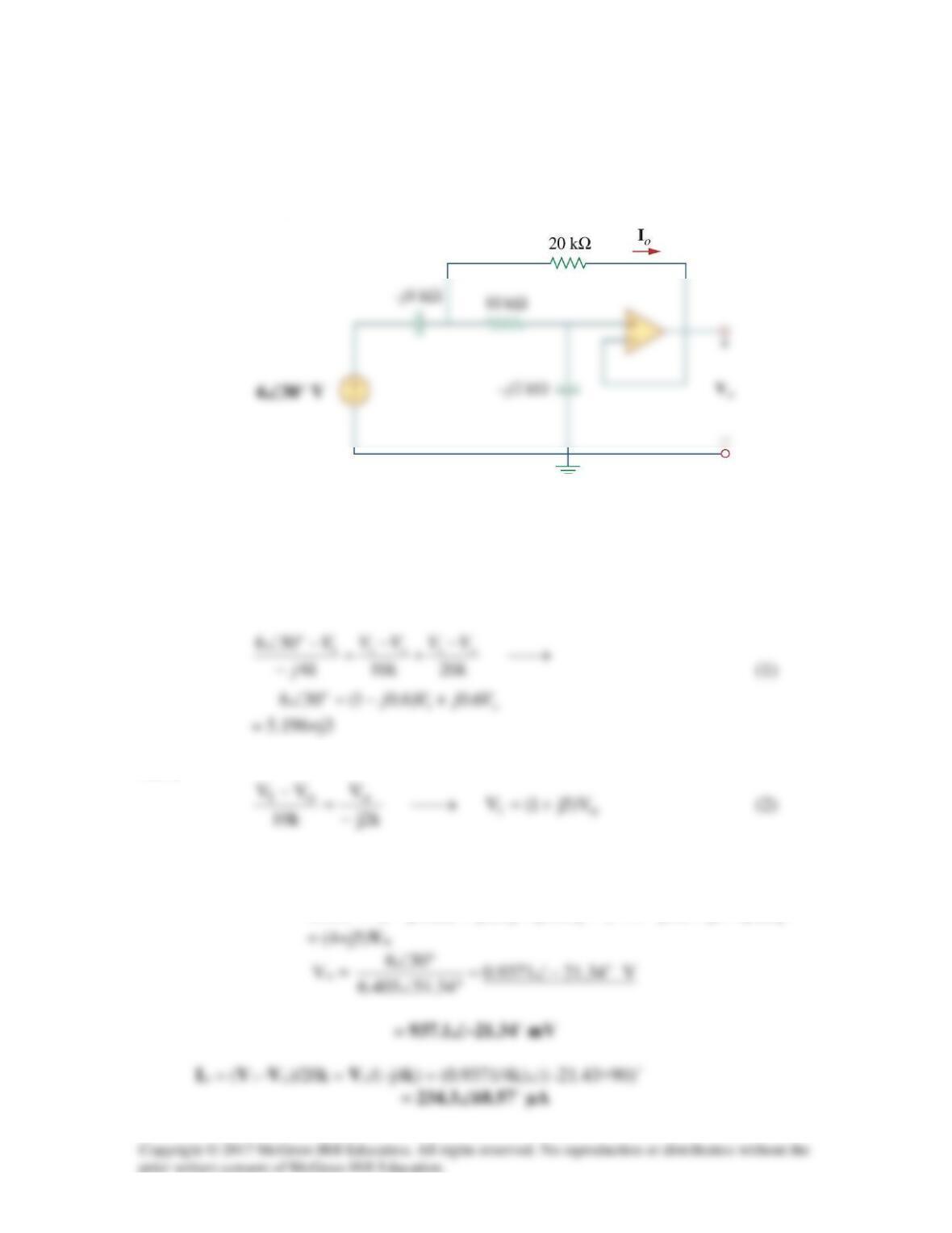
Determine Vo and Io in the op amp circuit of Fig. 10.119.
Figure 10.119
For Prob. 10.76.
Solution
Let the voltage between the –j4 k
Ω
capacitor and the 10 k
Ω
resistor be V1.
Also,
Solving (2) into (1) yields
VjjjVjVjj )656.031(6.0)51)(6.01(306 ++−+=++−=°∠
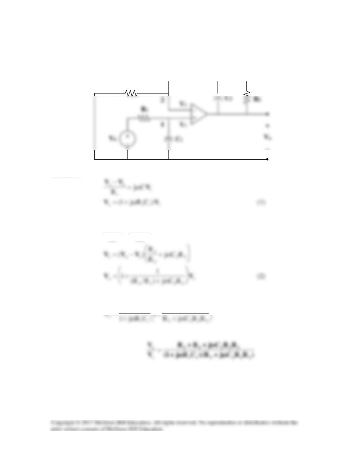
Solution 10.77
Consider the circuit below.
At node 1,
At node 2,
)(Cj
RR
0
o12
o1
1
VV
VV
V−ω+
−
=
−
From (1) and (2),
2
s
R
V
R1
R3
−
Solution 10.78
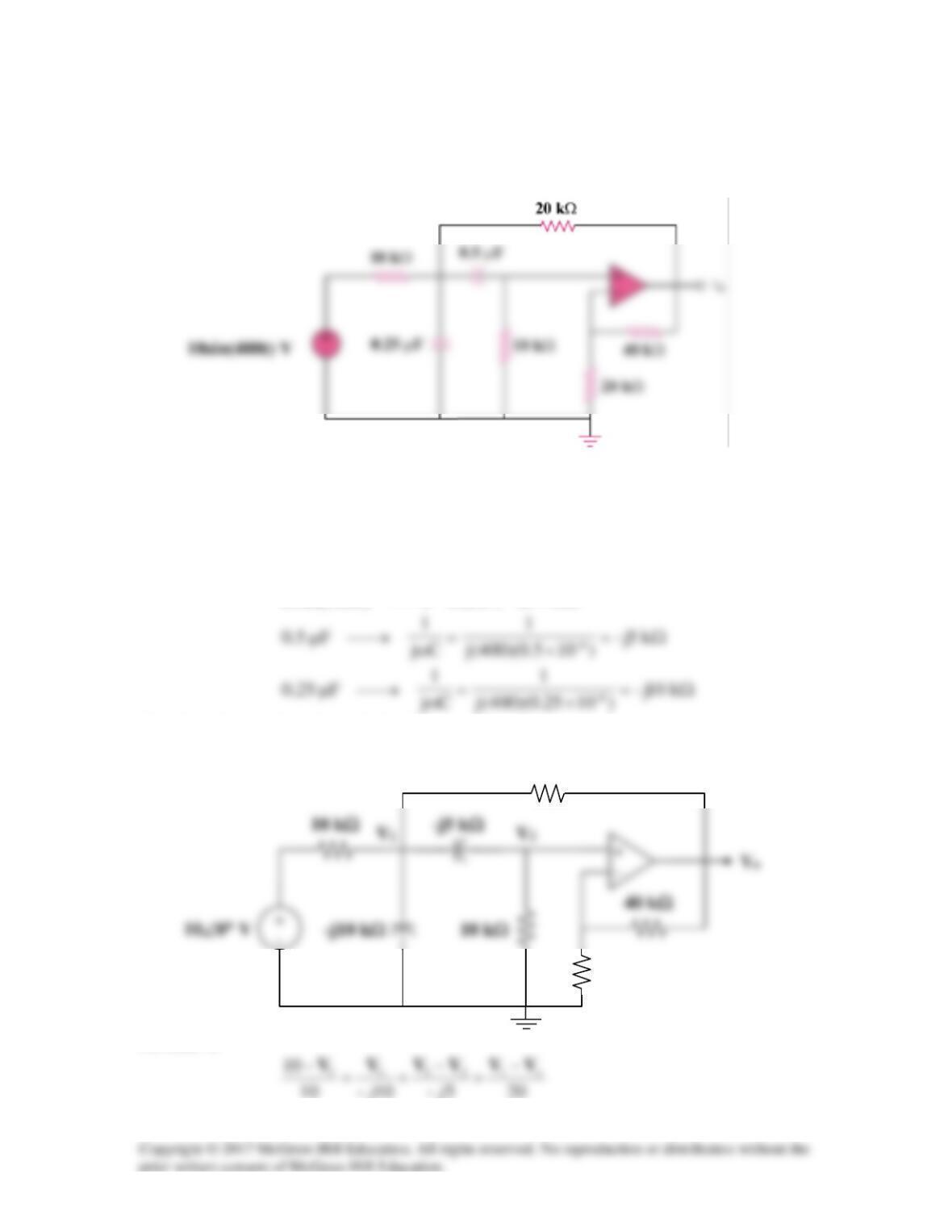
Determine vo(t) in the op amp circuit in Fig. 10.121 below.
Figure 10.121
For Prob. 10.78.
Solution
400,010)400sin(10 =°∠→
ω
t
Consider the circuit as shown below.
At node 1,
40 kΩ
10 kΩ
20 kΩ
20 kΩ
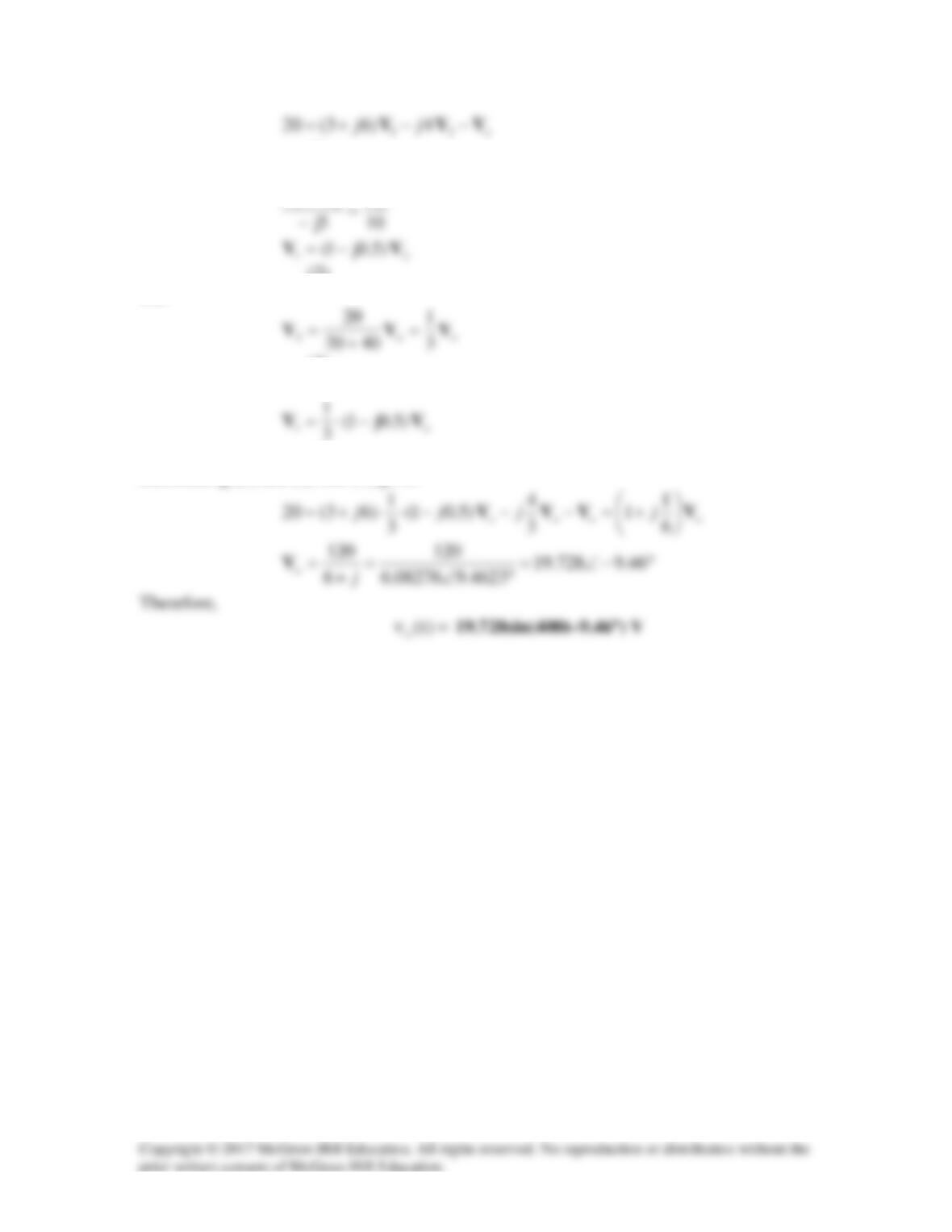
(1)
At node 2,
221
VVV =
−
(2)
But
(3)
From (2) and (3),
(4)
Substituting (3) and (4) into (1) gives
Solution 10.79
For the op amp circuit in Fig. 10.122, obtain Vo.
–j200 kΩ
100 kΩ
Figure 10.122
For Prob. 10.79.
Solution
First we label all the unknown nodes in the circuit.
–j200 kΩ
100 kΩ
−
200 kΩ
200 kΩ
This leads to the following,
Solution 10.80
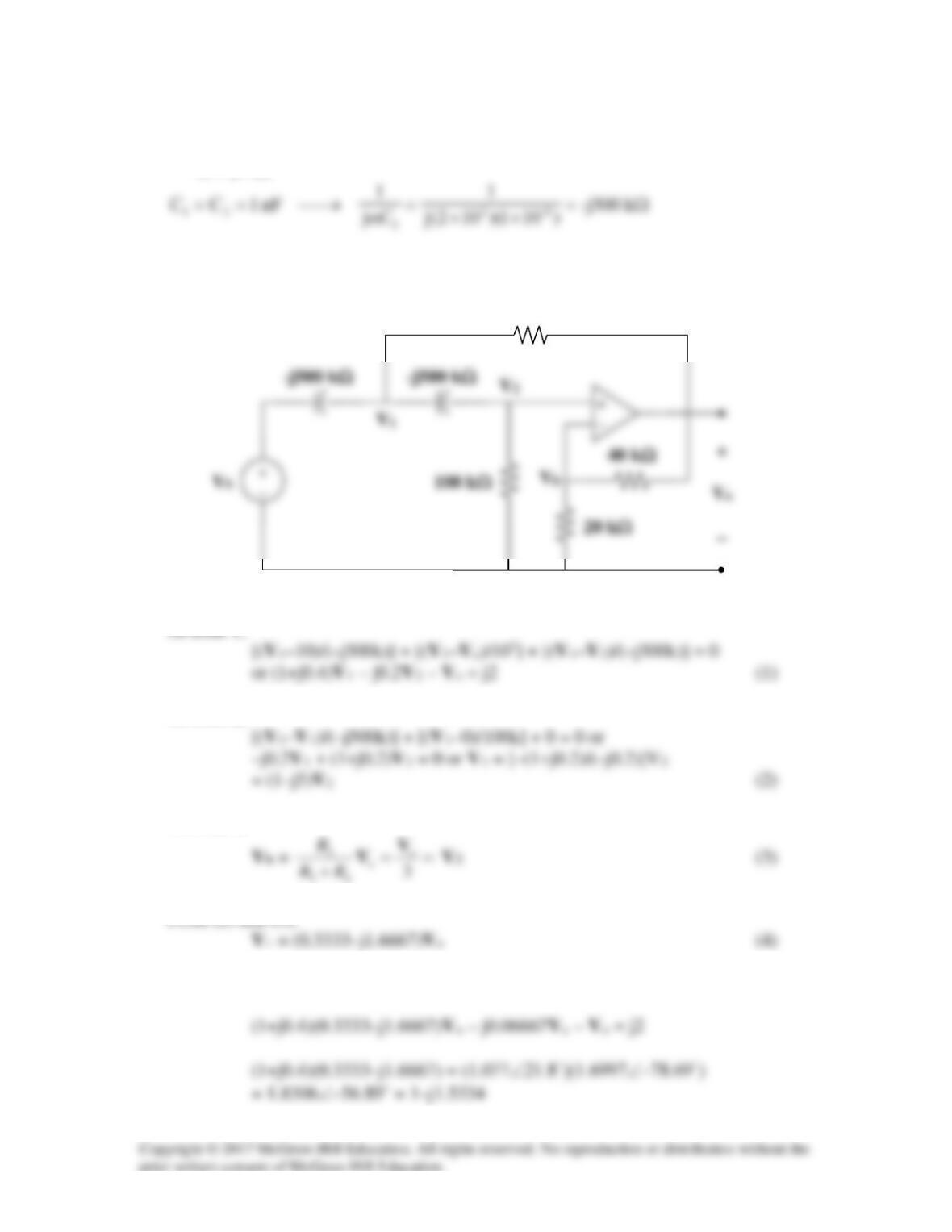
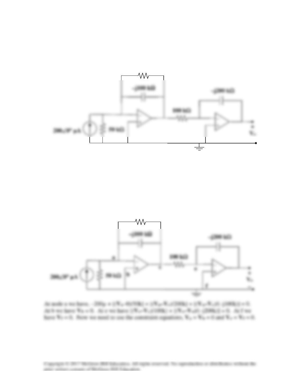
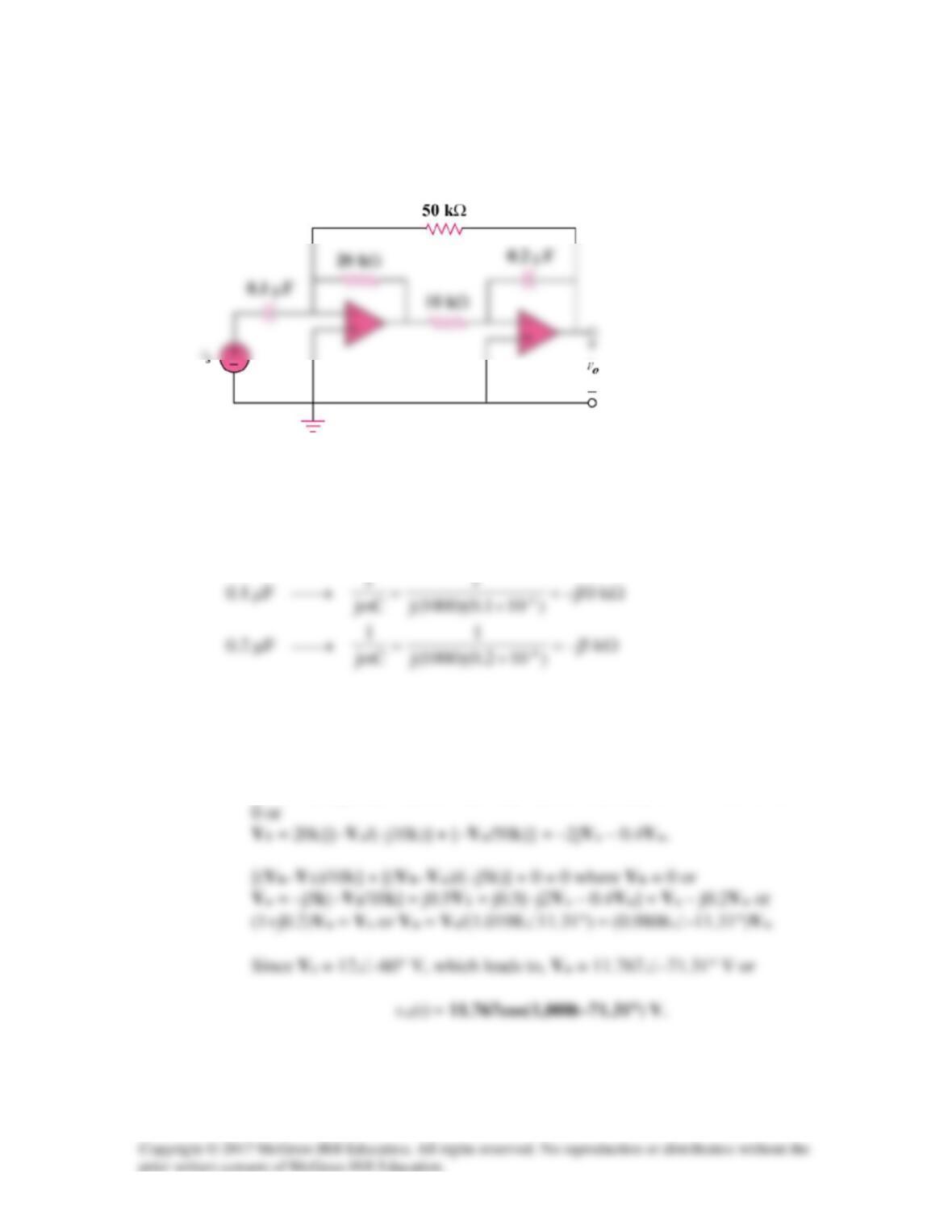
Obtain vo(t) for the op amp circuit in Fig. 10.123 if vs = 12cos (1000t – 60°) V.
Figure 10.123
For Prob. 10.80.
Solution
1000,60–12)601000cos(12 =°∠→°−
ω
t
Let the input to the inverting terminal of the first op amp be Va, the output of the first op
amp be V1, and the input to the inverting terminal of the second op amp be Vb. This then
gives us the following node equations,
[(Va–Vs)/(–j10k)] + [(Va–Vo)/50k] + [(Va–V1)/20k] + 0 = 0 where Va =
1
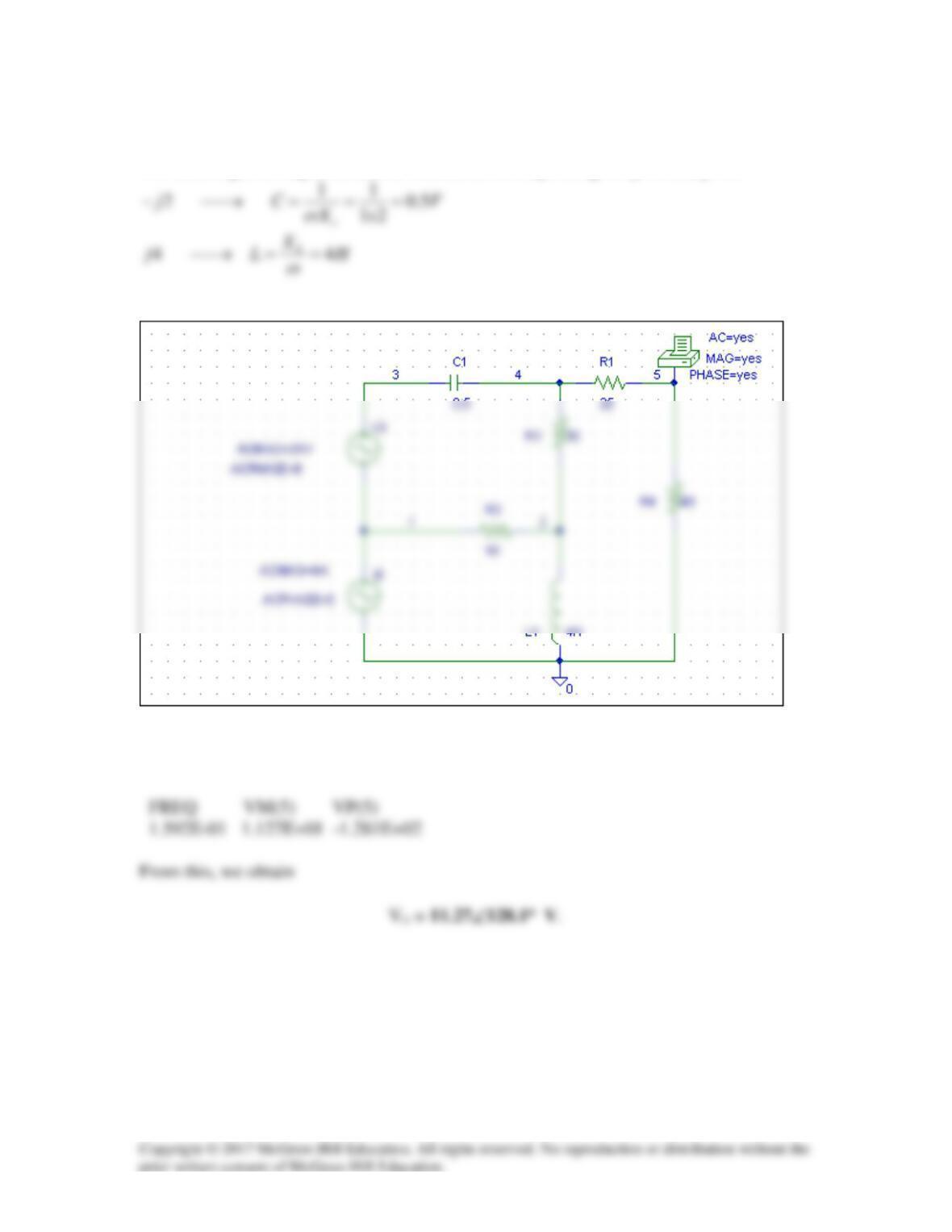
Solution 10.81
We need to get the capacitance and inductance corresponding to –j2 Ω and j4 Ω.
The schematic is shown below.
When the circuit is simulated, we obtain the following from the output file.
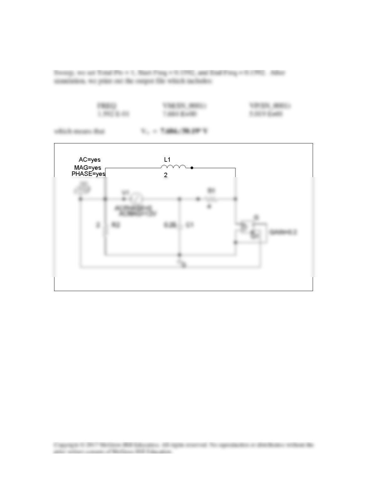
Solution 10.82
The schematic is shown below. We insert PRINT to print Vo in the output file. For AC