++−+−
=
)853.2)(2306.14265.16347.0)(4265.16347.0(
7
jjj
D
Solution 16.62
Using Fig. 16.85, design a problem to help other students better understand solving for
node voltages by working in the s-domain.
Although there are many ways to solve this problem, this is an example based on the
same kind of problem asked in the third edition.
Problem
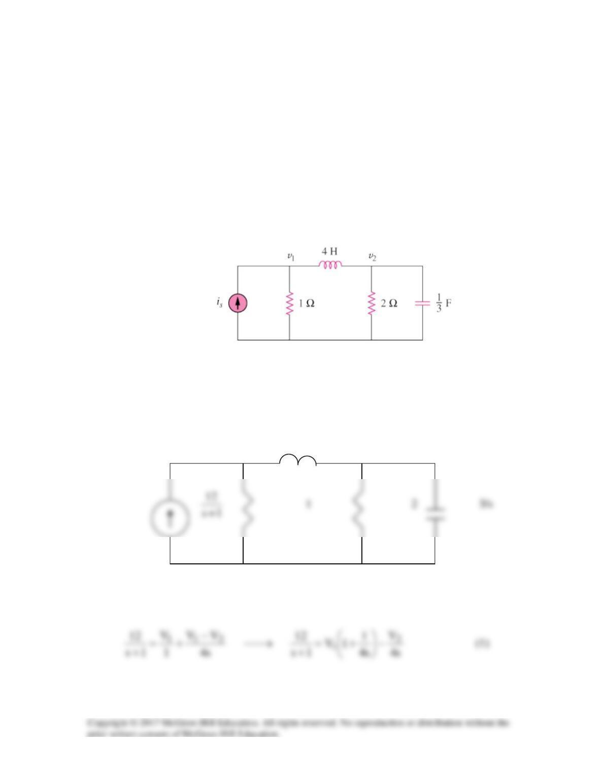
Find the node voltages v1 and v2 in the circuit of Fig. 16.85 using Laplace transform
technique. Assume that is = 12e-t u(t) A and that all initial conditions are zero.
Figure 16.85
For Prob. 16.62.
Solution
The s-domain version of the circuit is shown below.
4s
V1 V2
At node 1,
At node 2,
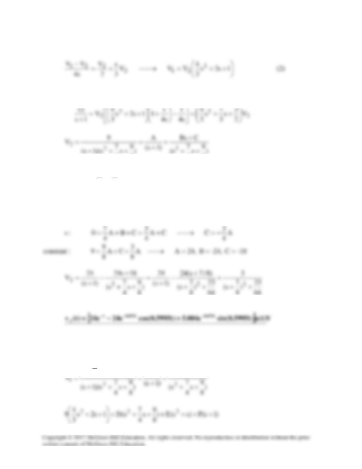
Substituting (2) into (1),
8
4
8
4
)1s(C)ss(B)
8
9
s
4
7
s(A9
22
++++++=
Equating coefficients:
BA0:s
2
+=
Taking the inverse of this produces:
Similarly,
FEs
D
1s2s
3
4
9
2
+
++
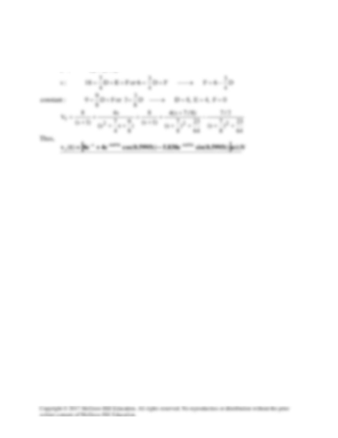
Equating coefficients:
ED12:s2+=
V
I
Solution 16.63
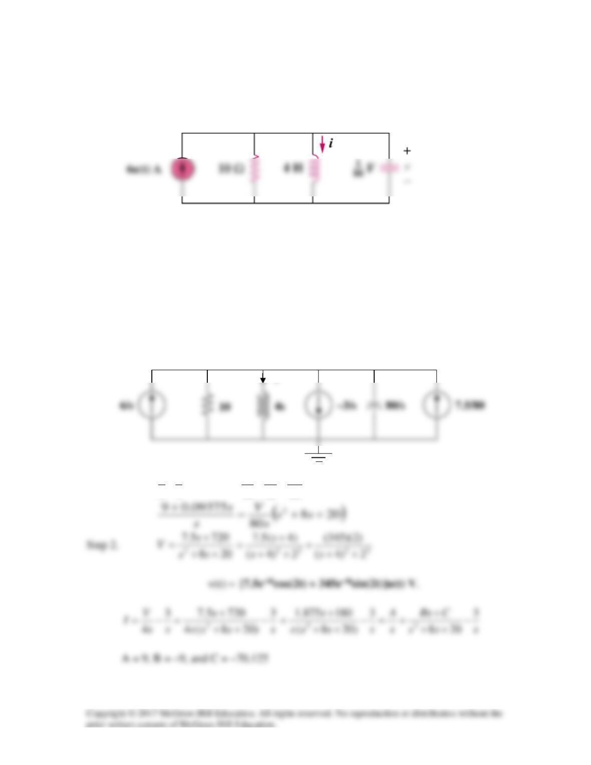
Consider the parallel RLC circuit of Fig. 16.86. Find v(t) and i(t) given that
v(0) = 7.5 and i(0) = –3 A.
Figure 16.86
For Prob. 16.63.
Solution
Step 1. We now need to transform the circuit into the s-domain and solve for V
using nodal analysis. Once we have V we can find I = [V/(4s)] – 3/s. Both terms
can now have a partial fraction expansion and transformed back into the time
domain.
At the non-reference node,
80410
09375.0
36 sV
s
VV
ss ++=++
or
Solution 16.64
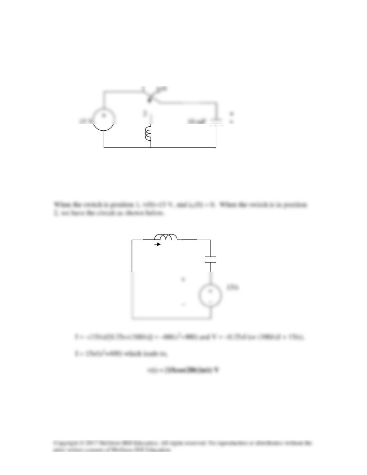
The switch in Fig. 16.87 moves from position 1 to position 2 at t = 0. Find v(t), for all
t > 0.
0.25 H
Figure 16.87
For Prob. 16.64.
Solution
s/4
+
100/s
_
–
I
Solution 16.65
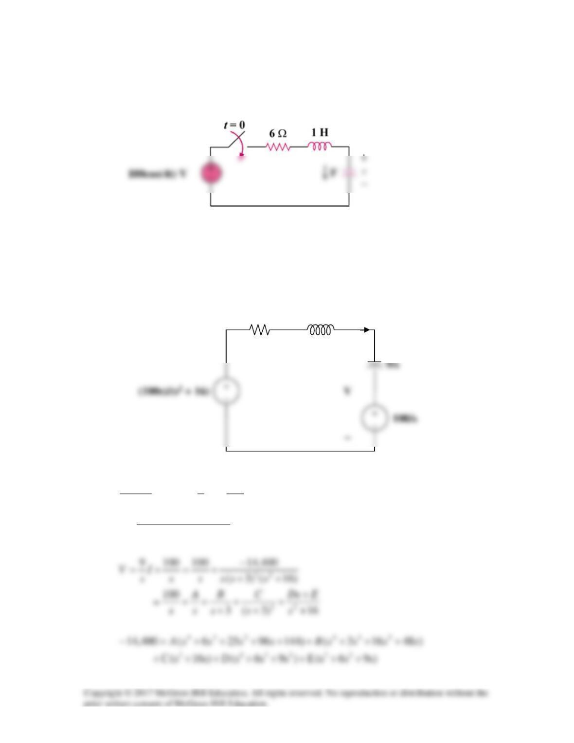
For the RLC circuit shown in Fig. 16.88, find the complete response if v(0) = 100 V when
the switch is closed.
Figure 16.88
For Prob. 16.65.
Solution
For
0t >
, the circuit in the s-domain is shown below.
Applying KVL,
0
1009
6
16
100
2
=+
+++
+
−
s
I
s
s
s
s
)16)(96(
600,1
22
+++
−
=sss
I
s
6
I
+
Equating coefficients :
0
s
:
A144400,14 =−
(1)
1
s
:
E9C16B48A960 +++=
(2)
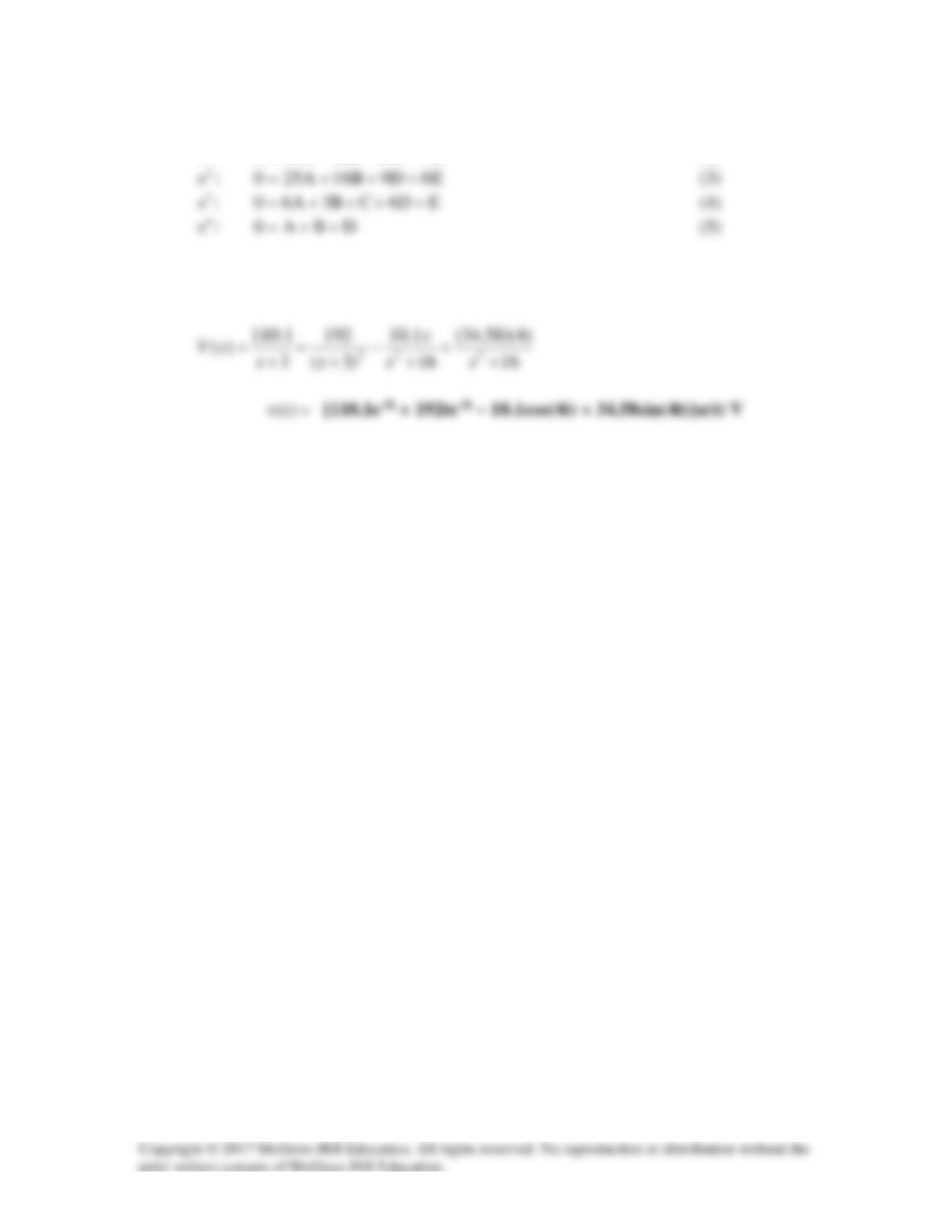
Solving equations (1), (2), (3), (4) and (5) gives
A = –100, B = 110.1, C = 192, D = 10.1, and E = 138.3.
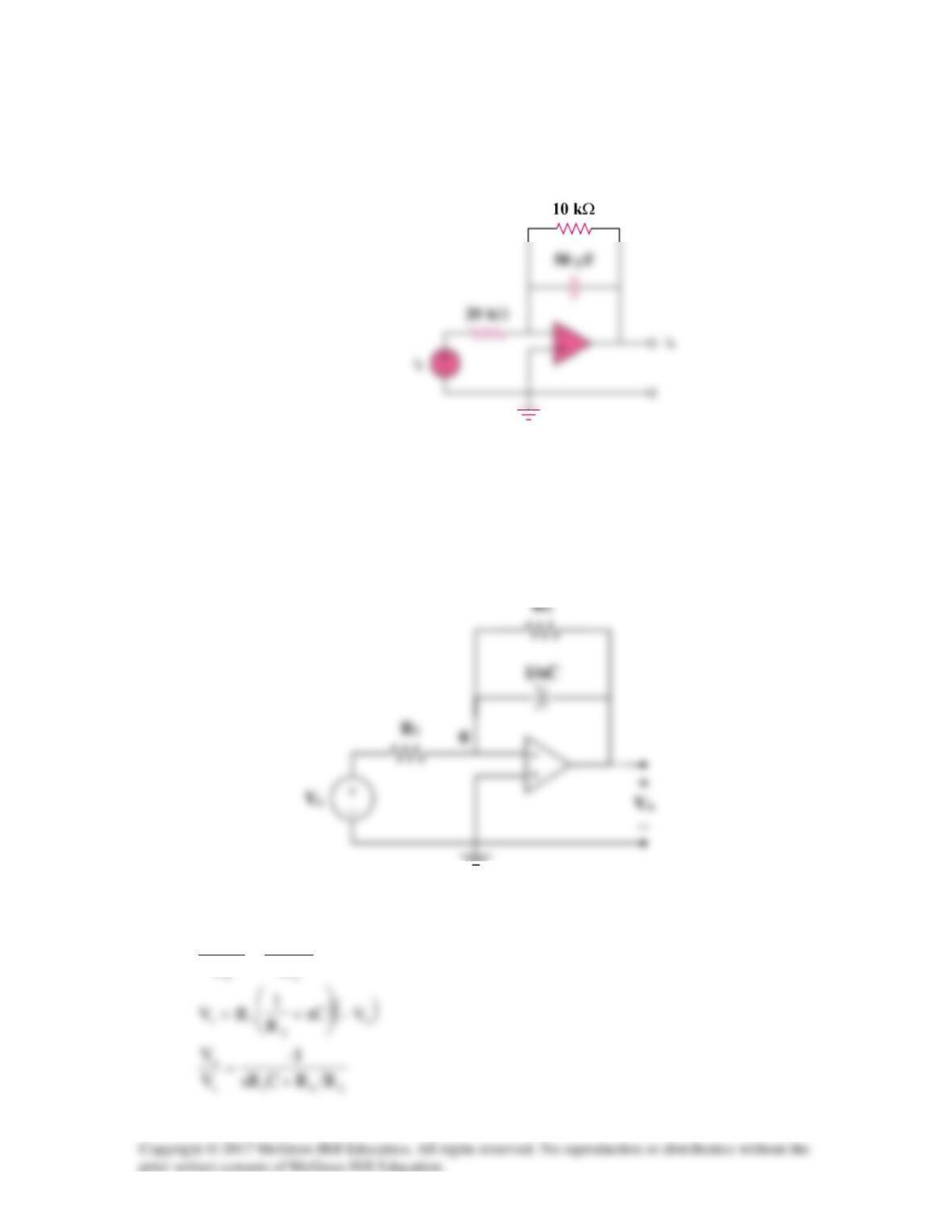
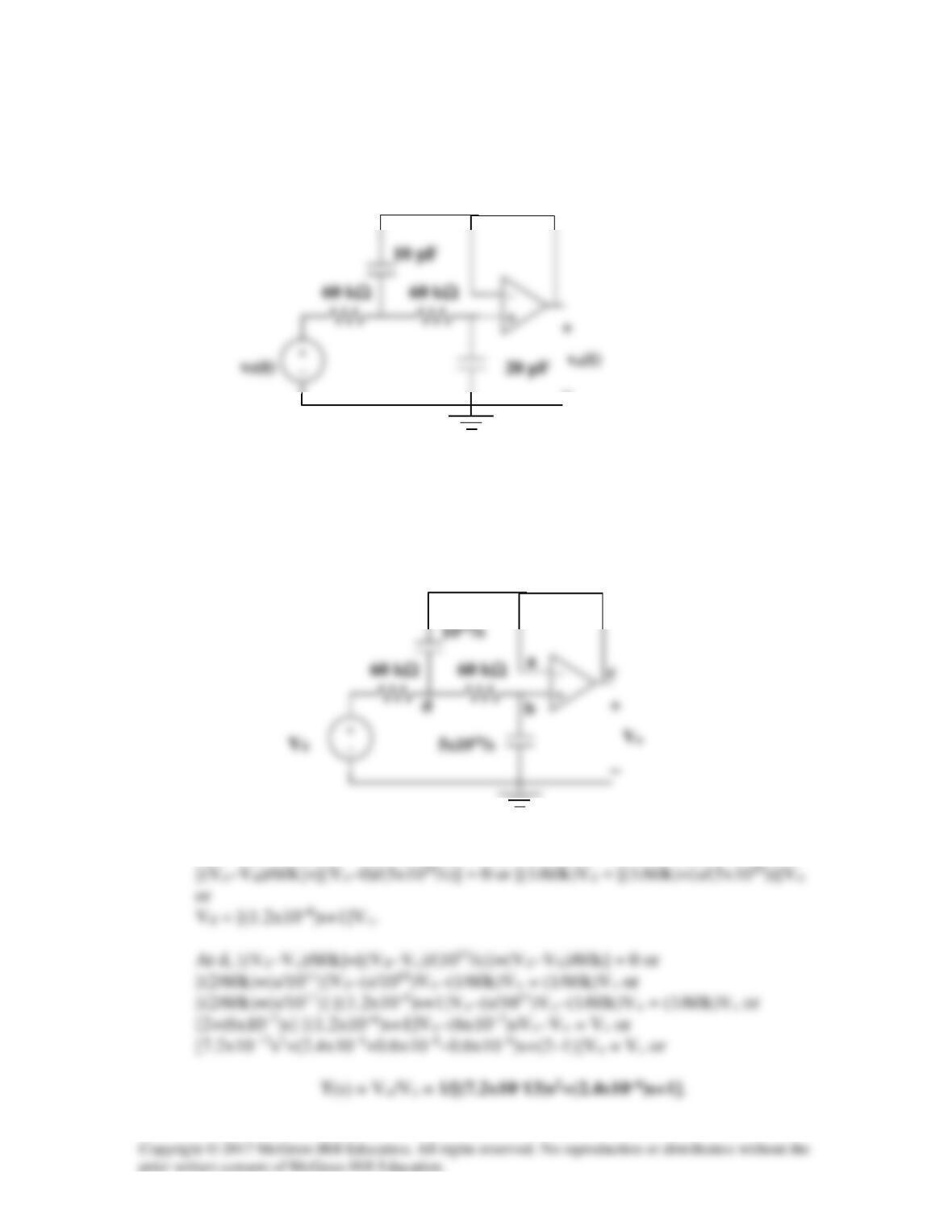
Solution 16.66
For the op amp circuit in Fig. 16.89, find vo(t) for t > 0. Take vs = 12 e–5t u(t) V.
Figure 16.89
For Prob. 16.66.
Solution
Consider the op-amp circuit below where R1 = 20 kΩ, R2 = 10 kΩ, C = 50 µF, and
vs(t) = [12e–5t]u(t) V.
At node 0,
sC)V0(
R
V0
R
0V
o
o
s
−+
−
=
−
But
2
10
20
R
R
2
1
==
,
1)1050)(1020(CR
6–
3
1
=××=
R
vo
−
C
R
105
105
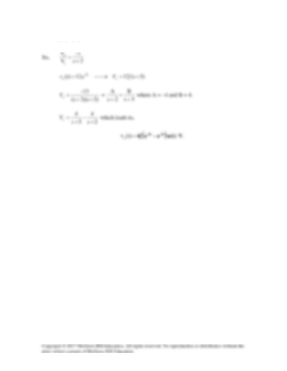
Solution 16.67
Given the op amp circuit in Fig. 16.90. If v1(0+) = 2 V and v2(0+) = 0 V, find vo for t > 0.
Let R = 100 kΩ and C = 1
µ
F.
Figure 16.90For Prob. 16.67.
Solution
Step 1. Convert the circuit into the s-domain and insert initial conditions. Next,
solve for Vo(s), then obtain the partial fraction expansion and convert back into
the time domain.
Step 2. sVc + 10Vo = –2 and 10Vc + sVo = 0 or Vc = –0.1sVo thus,
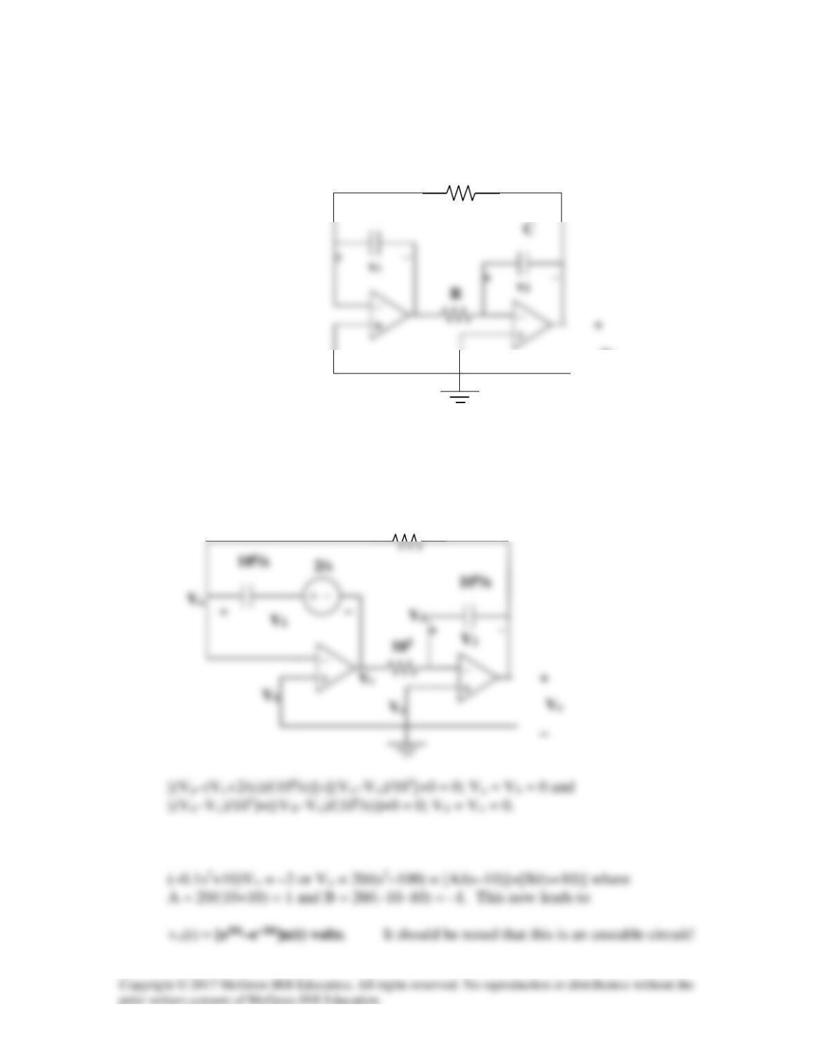
Solution 16.68
Obtain Vo/Vs in the op amp circuit in Fig. 8.91.
Figure 8.91
For Prob. 8.68.
Solution
Step 1. Convert the circuit into the s-domain and then solve for Vo(s) in terms of
Vs(s). Then solve for Vo/Vs = T(s).
At a, Va = Vb = Vc = Vo. At b, [(Vb–Vd)/60k]+[(Vb–0)/(5×1010/s)]+0 = 0 or
−
Solution 16.69
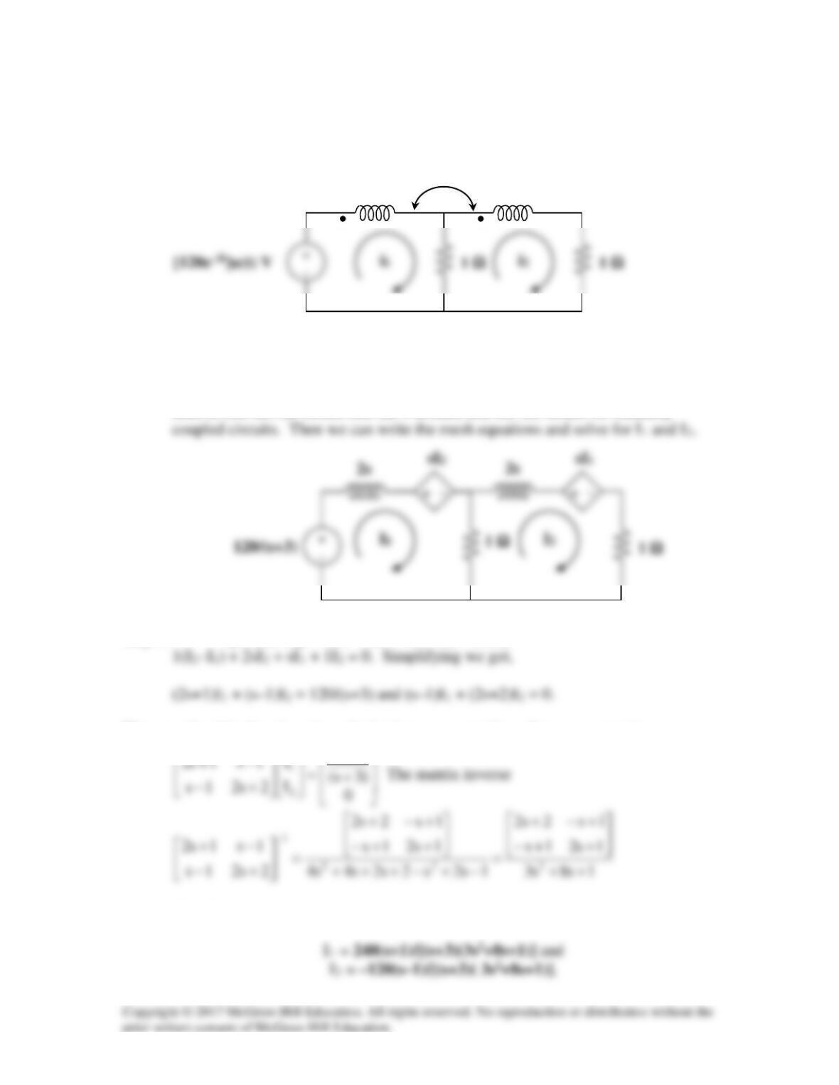
Find I1(s) and I2(s) in the circuit of Fig. 16.92.
Figure 16.92 For Prob. 16.69.
Solution
Step 1. We note that the initial conditions in this case are equal to zero. Next, we
need to convert the circuit into the s-domain and use the model for mutually
Step 2. –[120/(s+3)] + 2sI1 + sI2 + 1(I1–I2) = 0 and
We can solve this directly using substitution or use matrices. Let us use matrices.
120
Therefore,
2 H
2 H
1 H
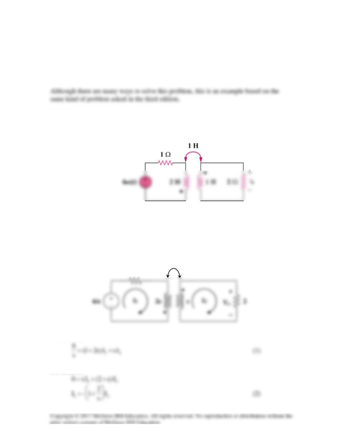
Solution 16.70
Using Fig. 16.93, design a problem to help other students better understand how to do
circuit analysis with circuits that have mutually coupled elements by working in the s–
domain.
Problem
For the circuit in Fig. 16.93, find vo(t) for t > 0.
Figure 16.93
For Prob. 16.70.
Solution
Consider the circuit shown below.
For mesh 1,
For mesh 2,
s
1
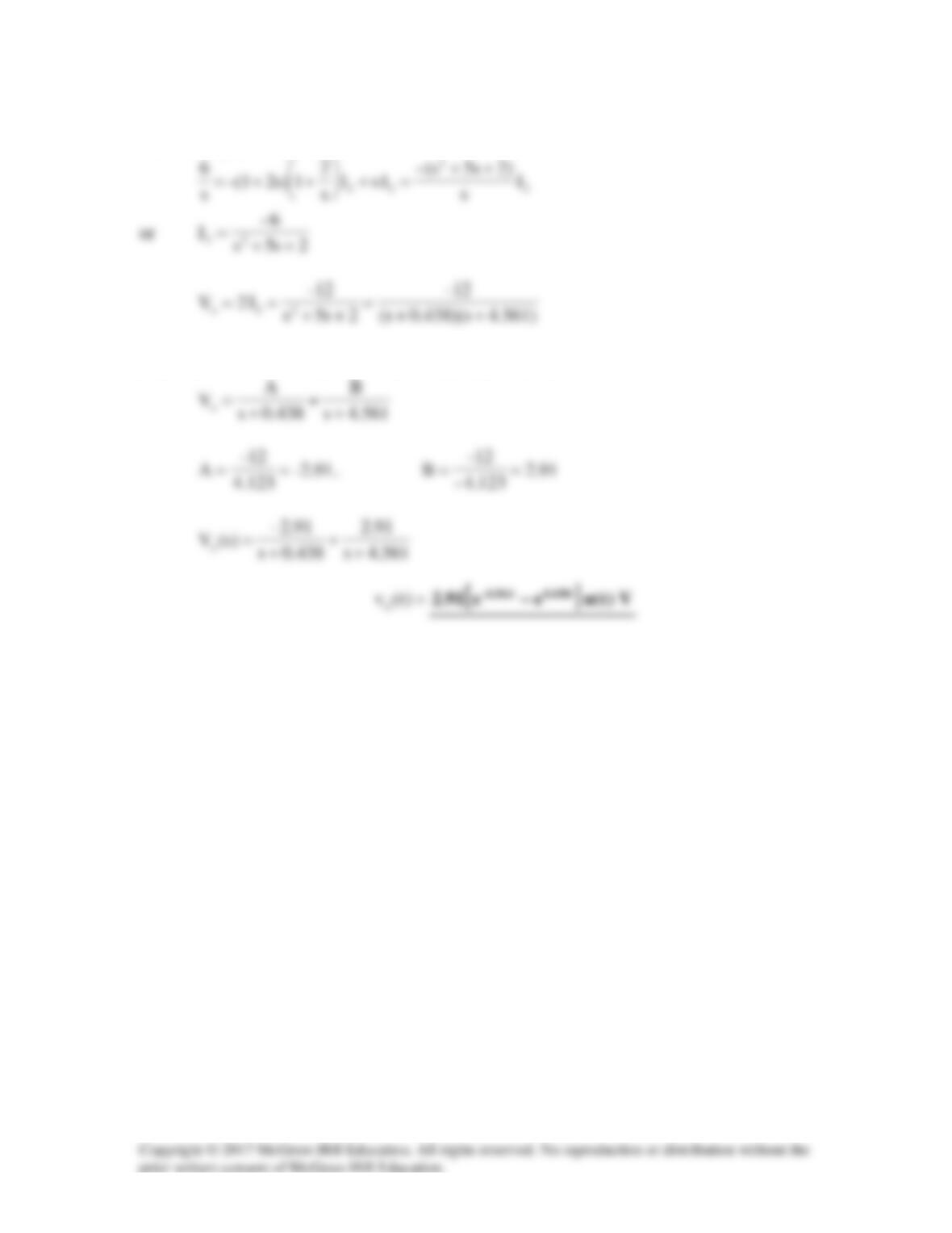
Substituting (2) into (1) gives
Since the roots of
02s5s
2
=++
are -0.438 and -4.561,
Solution 16.71
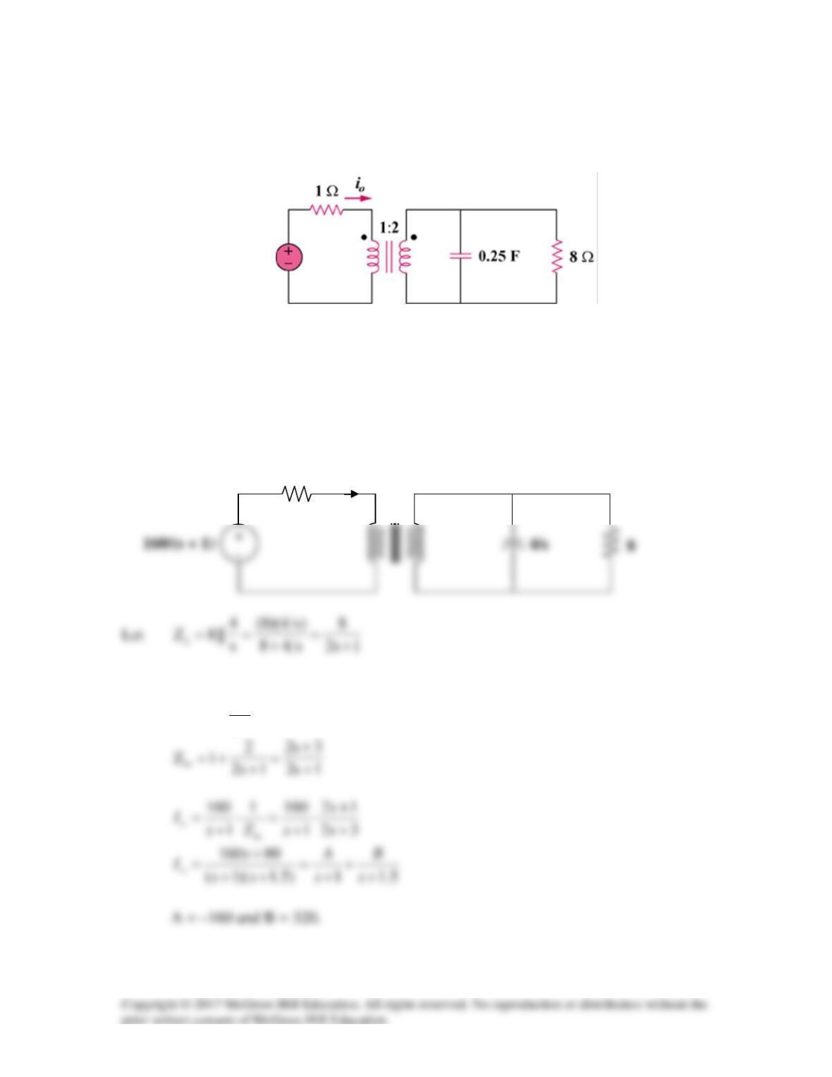
For the ideal transformer circuit in Fig. 16.94, determine io(t).
Figure 16.94
For Prob. 16.71.
Solution
Consider the following circuit.
When this is reflected to the primary side,
2n,
n
Z
1Z 2
L
in =+=
1
Io
1 : 2
160e–tu(t) V
Solution 16.72
The transfer function of a system is
2
() 31
s
Hs s
=+
Find the output when the system has an input of 14e–t/3 u(t).
Solution
() () ()Ys HsXs=
,
14 42
() 13 3 1
Xs ss
= =
++
Using the time differentiation property,
-t 3 -t 3 -t 3
-8 -8 -1
() (e )
9 93
d
g t t te e
dt
=⋅= +
Solution 16.73
When the input to a system is a unit step function, the response is 120 cos(2t). Obtain the
transfer function of the system.
Solution
s
1
)s(X)t(u)t(
x=→=