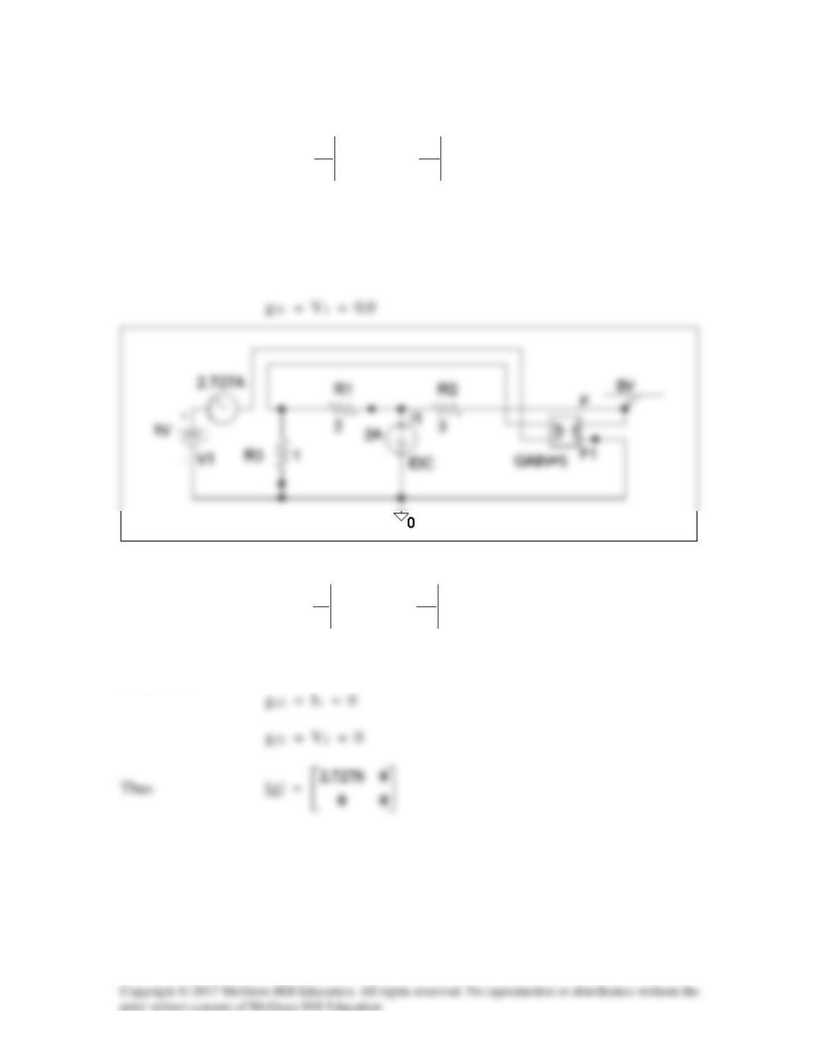
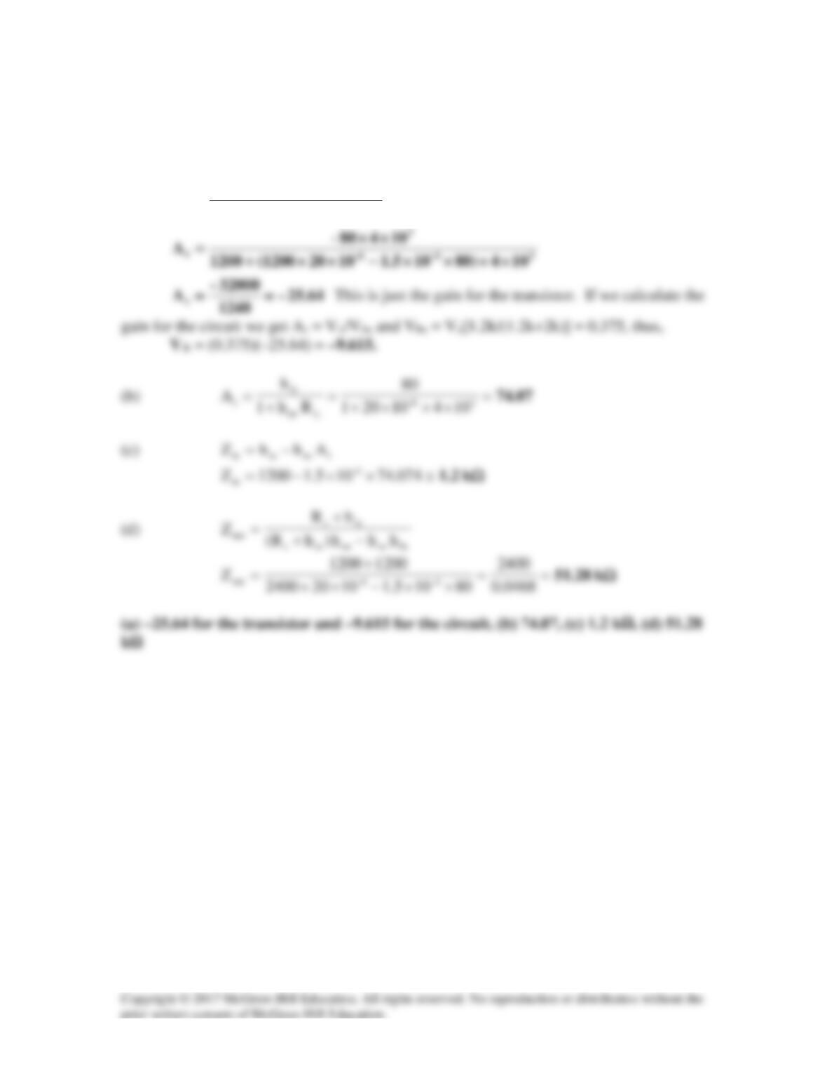
Solution 19.86
(a) By definition, g11 =
0I
1
1
2
V
I
=
, g21 =
0I
2
1
2
V
V
=
.
We let V1 = 1 V and open-circuit the output port. The schematic is shown below. After
simulation, we obtain
g11 = I1 = 2.7
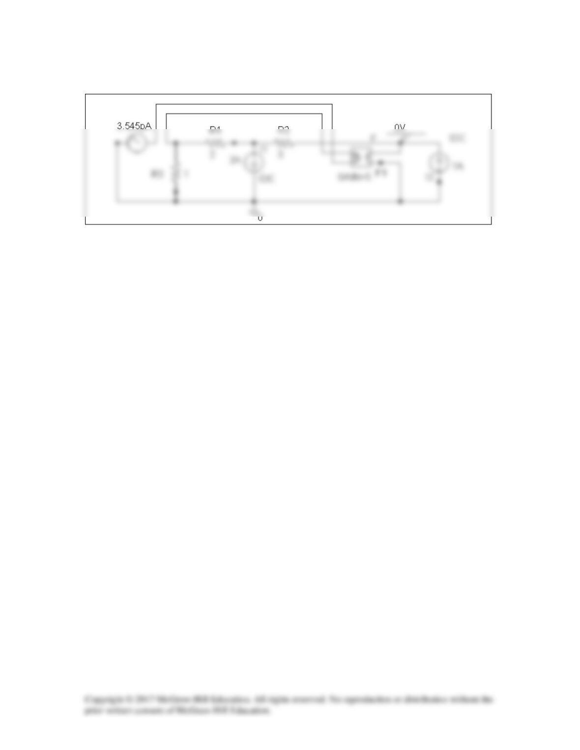
(b) Similarly,
g12 =
0V
2
1
1
I
I
=
, g22 =
0V
2
2
1
I
V
=
We let I2 = 1 A and short-circuit the input port. The schematic is shown below. After
simulation,
Solution 19.87
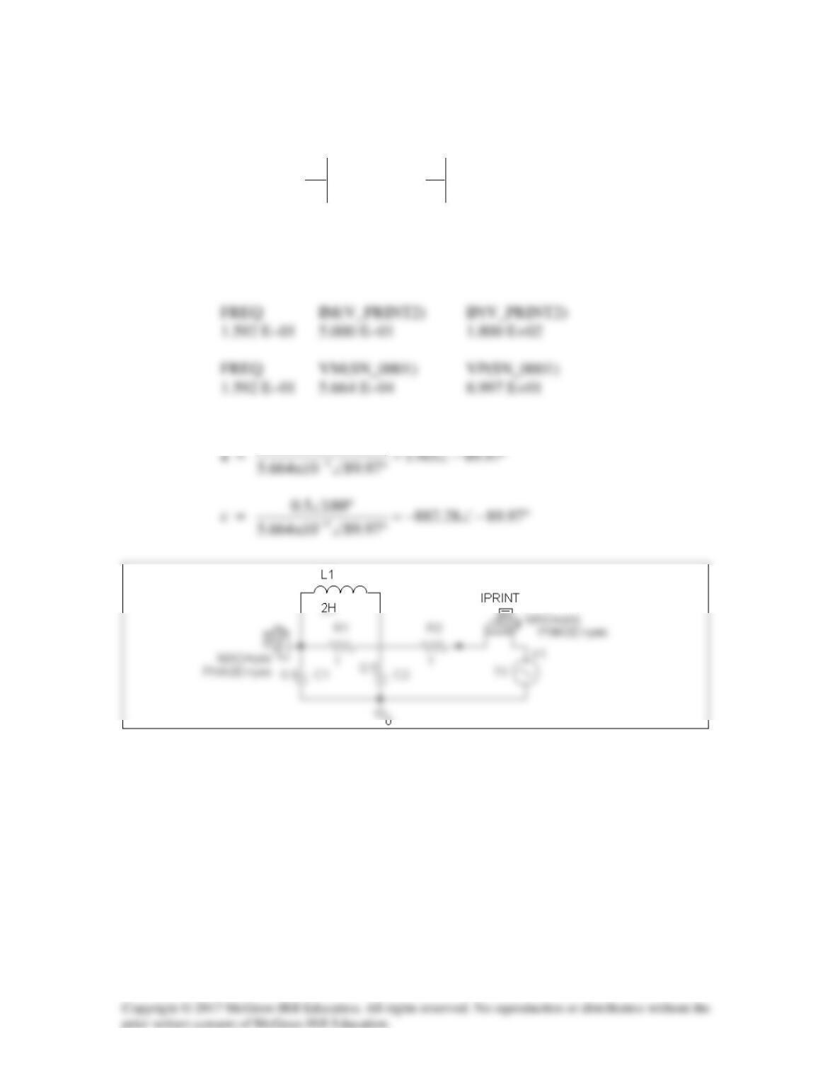
(a) Since a =
0I
1
2
1
V
V
=
and c =
0I
1
2
1
V
I
=
,
we open–circuit the input port and let V2 = 1 V. The schematic is shown below. In the
AC Sweep box, set Total Pts = 1, Start Freq = 0.1592, and End Freq = 0.1592. After
simulation, we obtain an output file which includes
From this,
1
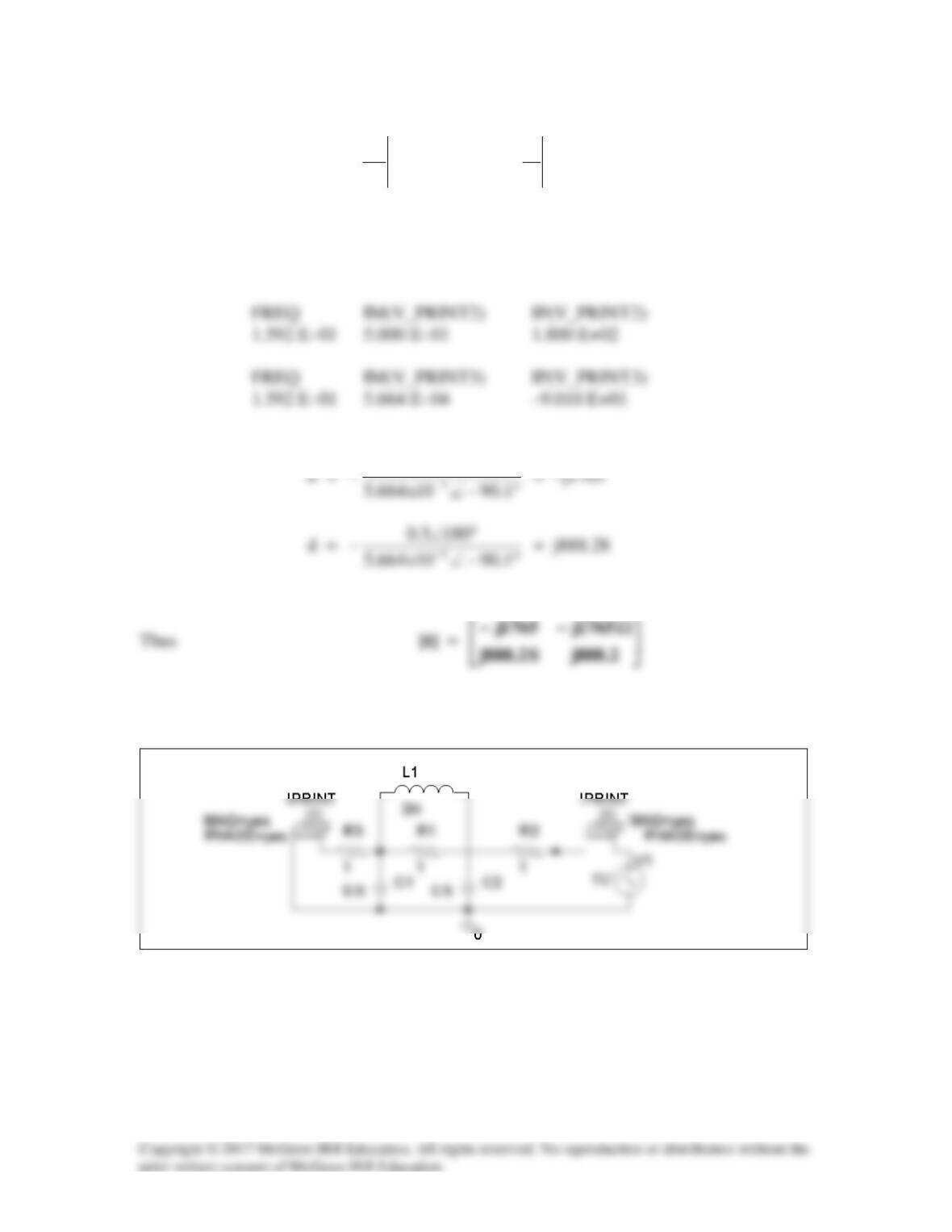
(b) Similarly,
b =
0V
1
2
1
I
V
=
−
and d =
0V
1
2
1
I
I
=
−
We short-circuit the input port and let V2 = 1 V. The schematic is shown below. After
simulation, we obtain an output file which includes
From this, we get
1
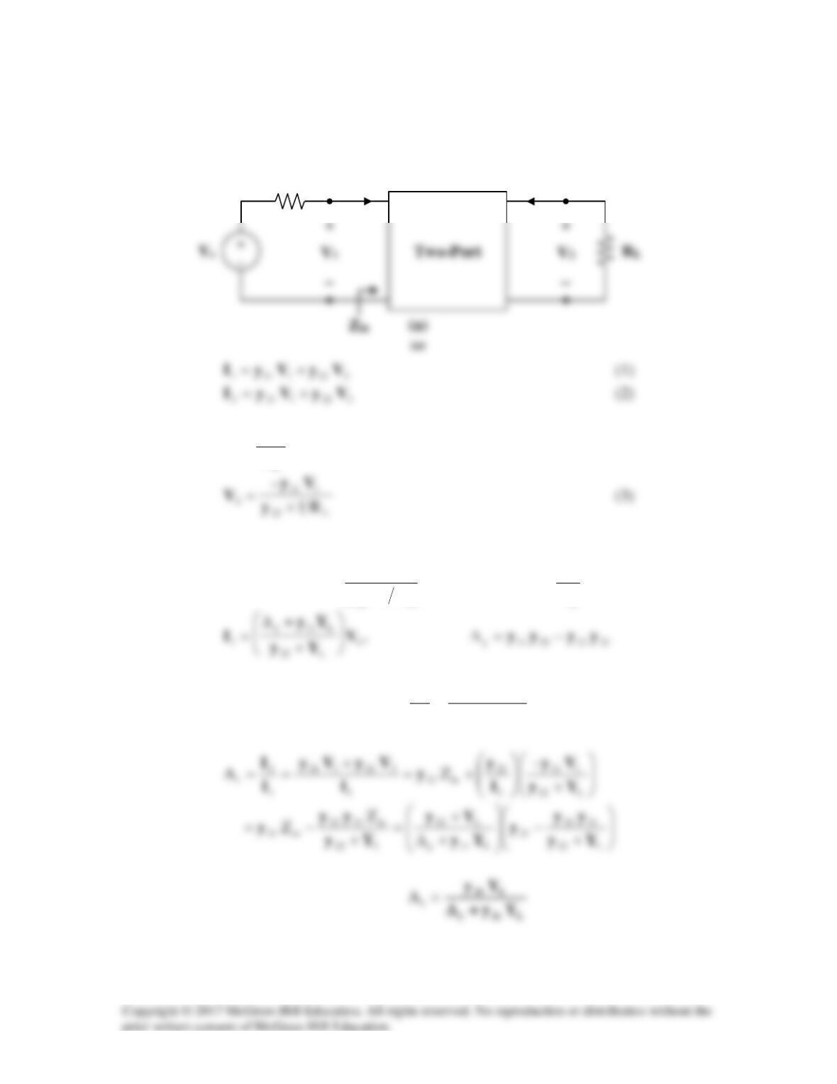
Solution 19.88
To get
in
Z
, consider the network in Fig. (a).
But
222121
L
2
2
R
–VyVy
V
I+==
Substituting (3) into (1) yields
+
⋅+=
L22
121
121111 R1
–
y
Vy
yVyI
,
L
L
R
1
=Y
or
==
1
1
in
ZI
V
L11y
L22
Yy
Yy
+∆
+
A
Rs
I1
I2
From (3),
2
V
21
y–
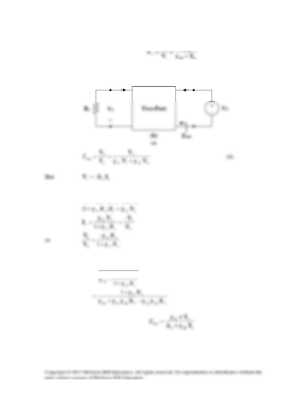
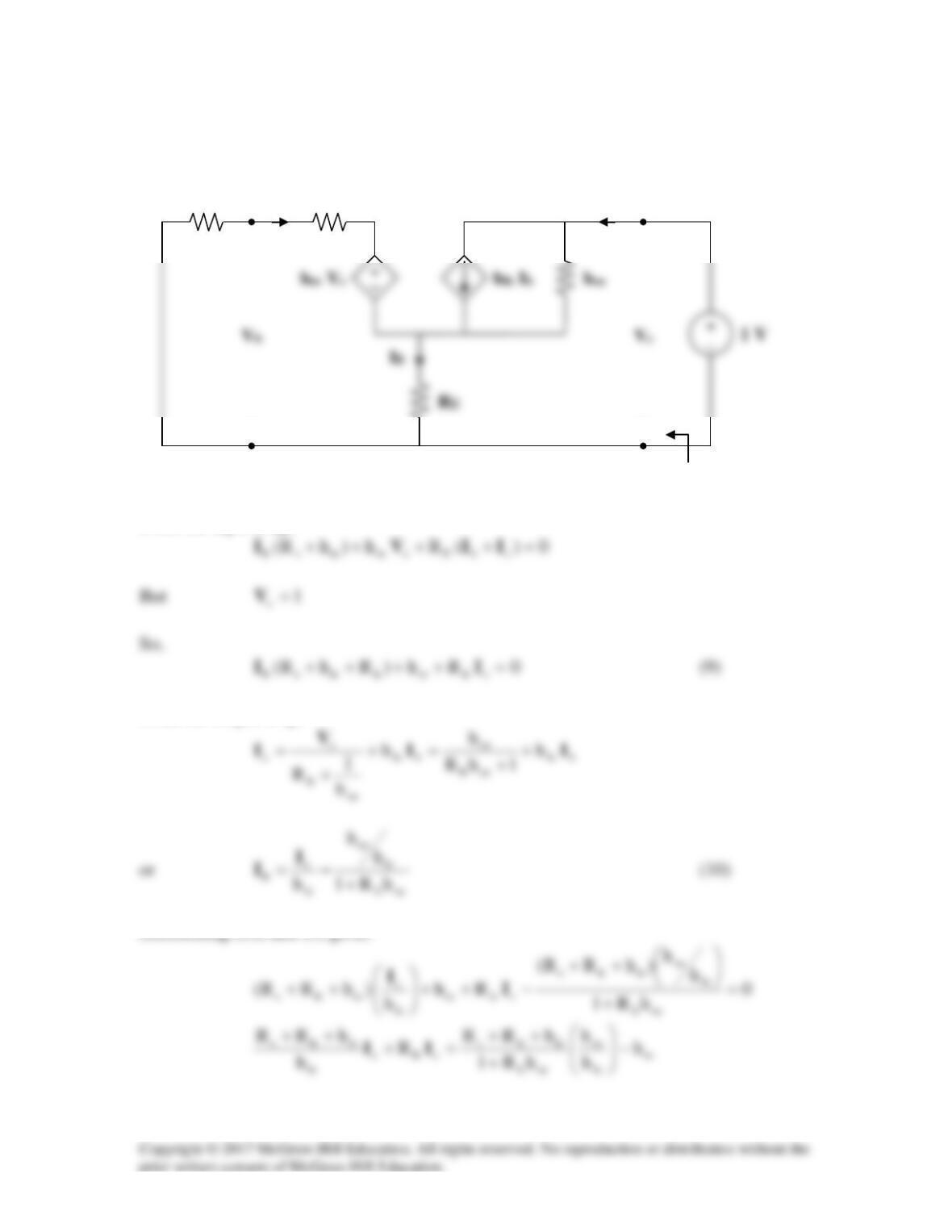
To get
out
Z
, consider the circuit in Fig. (b).
Substituting this into (1) yields
Substituting this into (4) gives
out
Z
s2112
out
R
1
Z
yy
=
I1
I2
+
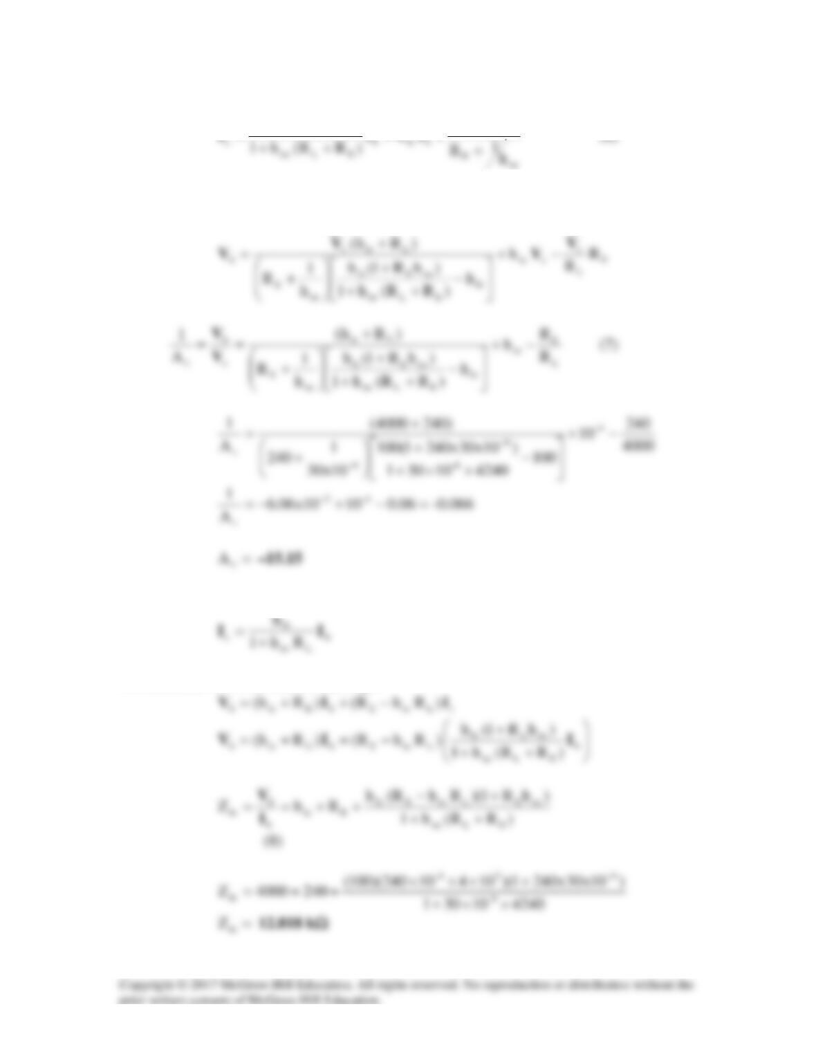
Solution 19.89
Lfereoeieie
Lfe
vR)hhhh(h
Rh–
A−+
=
Solution 19.90
(a)
Loe
Lfere
iein Rh1
Rhh
hZ +
−=
(b)
Lfereoeieie
Lfe
vR)hhhh(h
Rh–
A−+
=
Solution 19.91
Ω= k2.1R
s
,
Ω= k4R
L
(a)
Lfereoeieie
Lfe
t
R)hhhh(h
Rh–
A−+
=
Solution 19.92
Due to the resistor
Ω= 240R
E
, we cannot use the formulas in section 18.9.1. We will
need to derive our own. Consider the circuit in Fig. (a).
cbE III +=
(1)
Substituting (4) into (3),
c
oe
E
L
bfec
h
1
R
R
hIII +
−=
RL
hie
Zin
Ib
Ic
+
−
Rs
RE
+
−
(a)
(a)
From (3) and (5),
c
oeEfe
h)R1(h
+
Substituting (4) and (6) into (2),
EccrebEiebRh)Rh( IVIV +++=
From (5),
We substitute this with (4) into (2) to get
To obtain out
Z
, which is the same as the Thevenin impedance at the output, we introduce
a 1-V source as shown in Fig. (b).
From the input loop,
From the output loop,
Substituting (10) into (9) gives
hie
Z
out
Ib
Ic
+
−
Rs
+
−
(b)
(a)
re
oeE
ieEs
feoe
h
hR1
hRR
)hh(
−
+
++