
Solution 11.1
)t50cos(160)t(v =
Solution 11.2
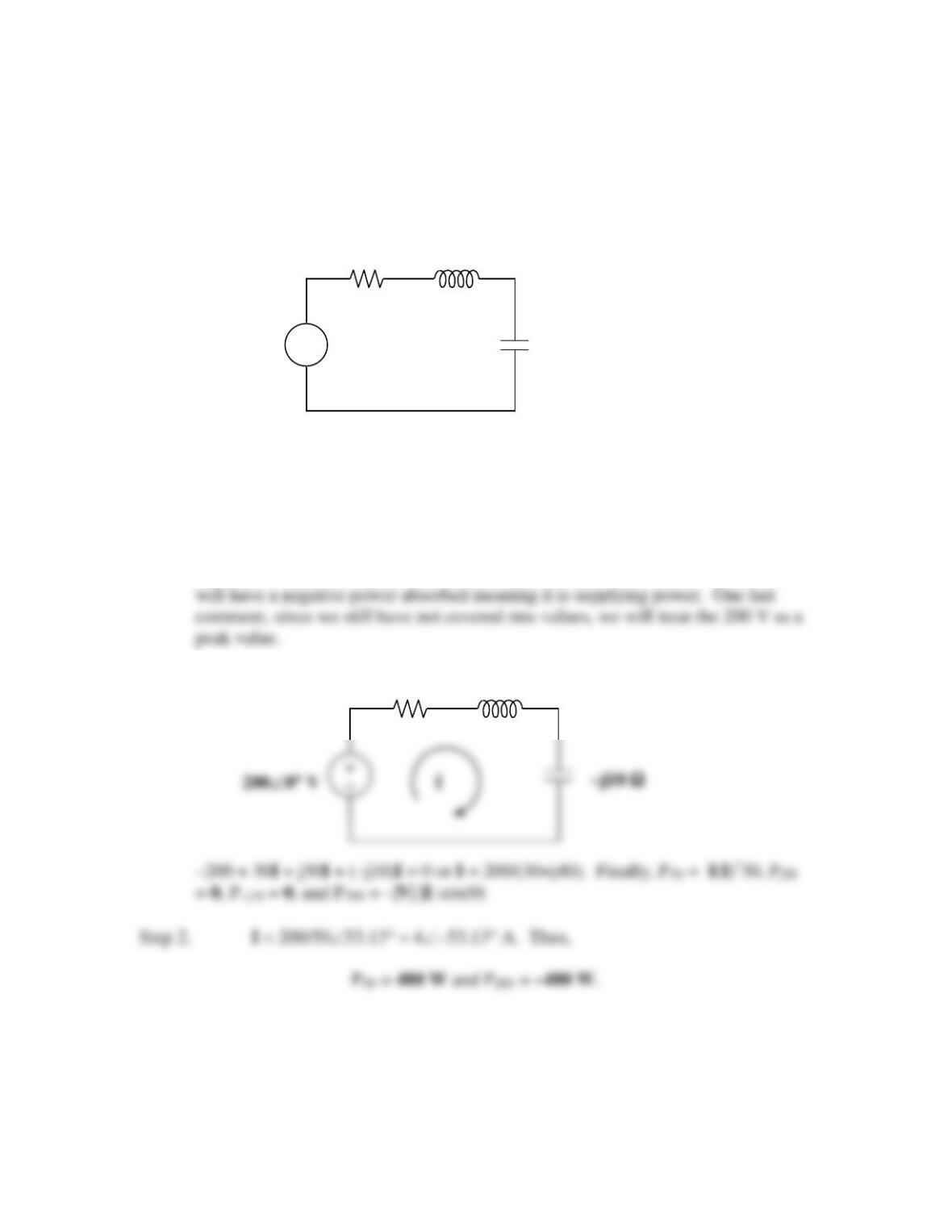
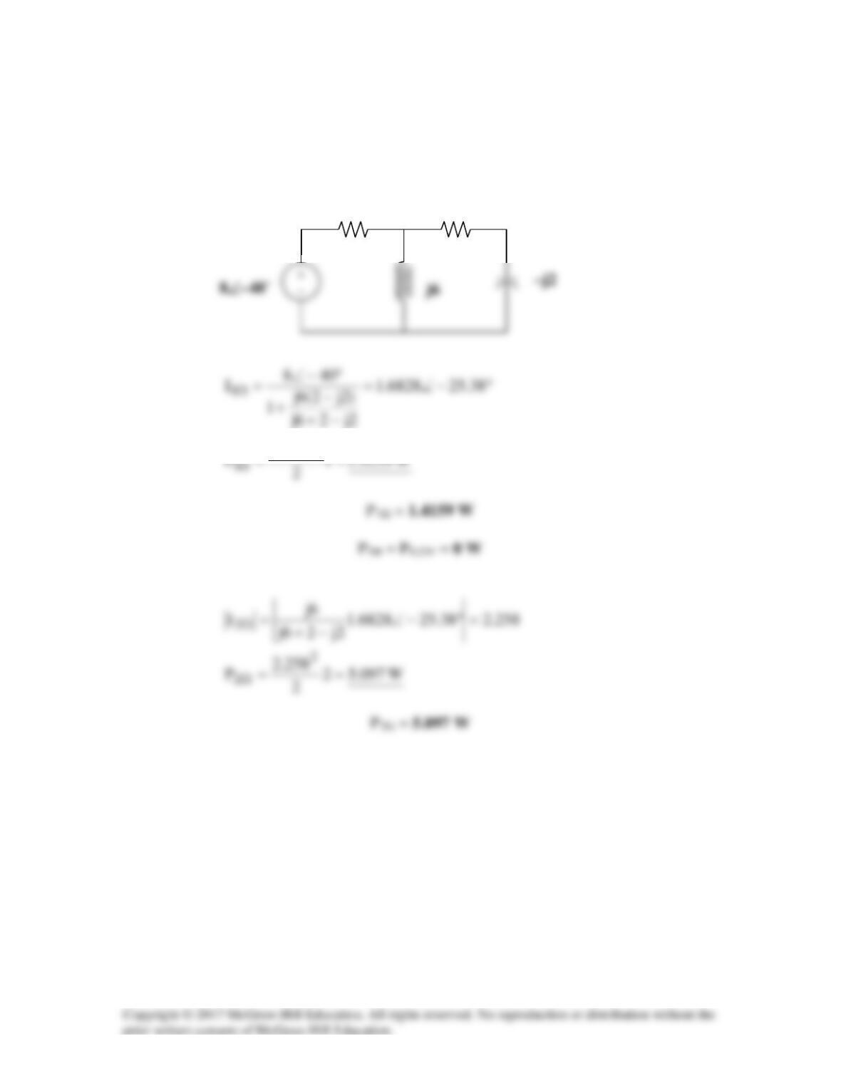
Given the circuit in Fig. 11.35, find the average power supplied or absorbed by each
element.
Figure 11.35
For Prob. 11.2.
Solution
Step 1. First we can write one mesh equation and solve for I. Once we have I, we
can then find the average power absorbed by each element. Obviously the source
200∠0° V
−
j50
Ω
30 Ω
200∠0° V
+
−
–j10 Ω
j50
Ω
30 Ω
Solution 11.3
I
11
Solution 11.4
Using Fig. 11.36, design a problem to help other students better understand instantaneous
Problem
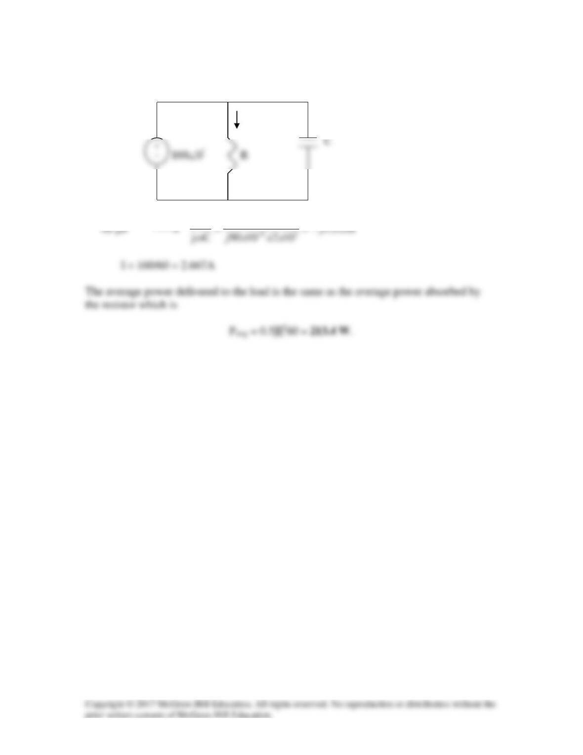
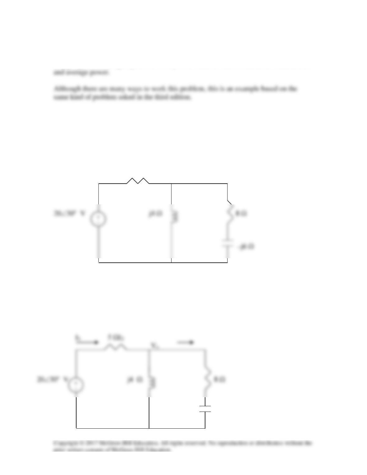
Find the average power dissipated by the resistances in the circuit of Fig. 11.36.
Additionally, verify the conservation of power. Note, we do not talk about rms values of
voltages and currents until Section 11.4, all voltages and currents are peak values.
5 Ω
Figure 11.36 For Prob. 11.4.
Solution
We apply nodal analysis. At the main node,
–j6 Ω
For the 5-Ω resistor,
For the 8-Ω resistor,
The complex power supplied is
Adding P1 and P2 gives the real part of S, showing the conservation of power.
Solution 11.5
Converting the circuit into the frequency domain, we get:
6828.1
2
2 Ω
1 Ω
Solution 11.6
33
20 mH 10 20 10 20jL j x x j
ω
−
→ = =
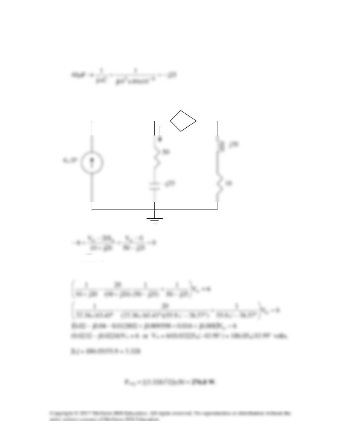
We apply nodal analysis to the circuit below.
Vo 20Ix
+ –
Ix
But
25j50
V
I
o
x
−
=
. Substituting this and solving for Vo leads
We can now calculate the average power absorbed by the 50–Ω resistor.
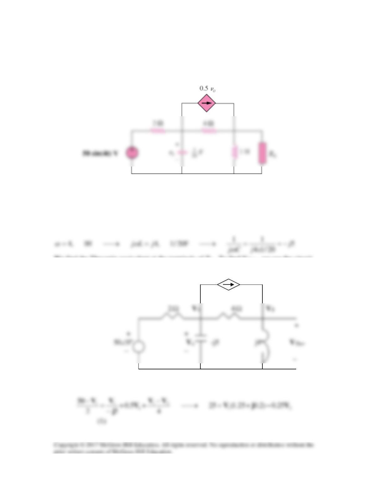
Solution 11.7
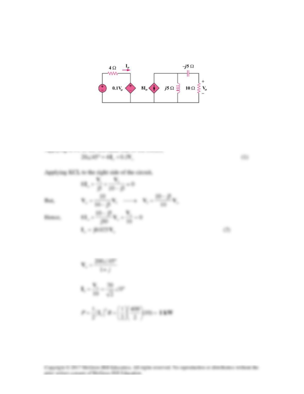
Given the circuit of Fig. 11.40, find the average power absorbed by the 10-Ω resistor.
Figure 11.40
For Prob. 11.7.
Solution
Substituting (2) into (1),
)1(1.04520 j
o
+=°∠ V
20∠45° V
We apply nodal analysis to the following circuit.
At node 1,
At node 2,
2
V
Substituting (1) into (2),
0j33360j 222 =+−− VVV
V1
V2
Io
I2
-j20 Ω
Solution 11.9
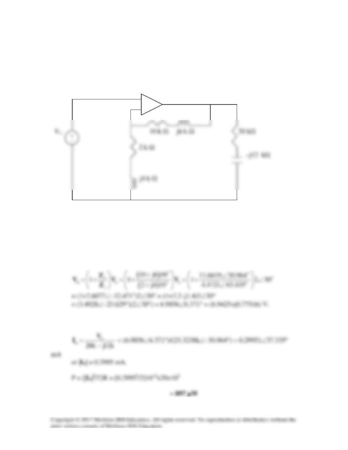
For the op amp circuit in Fig. 11.41, Vs = 2∠30o V. Find the average power absorbed by
the 20-kΩ resistor.
+
–
Figure 11.41
For Prob. 11.9.
Solution
This is a non-inverting op amp circuit. At the output of the op amp,
The current through the 20-kΩ resistor is

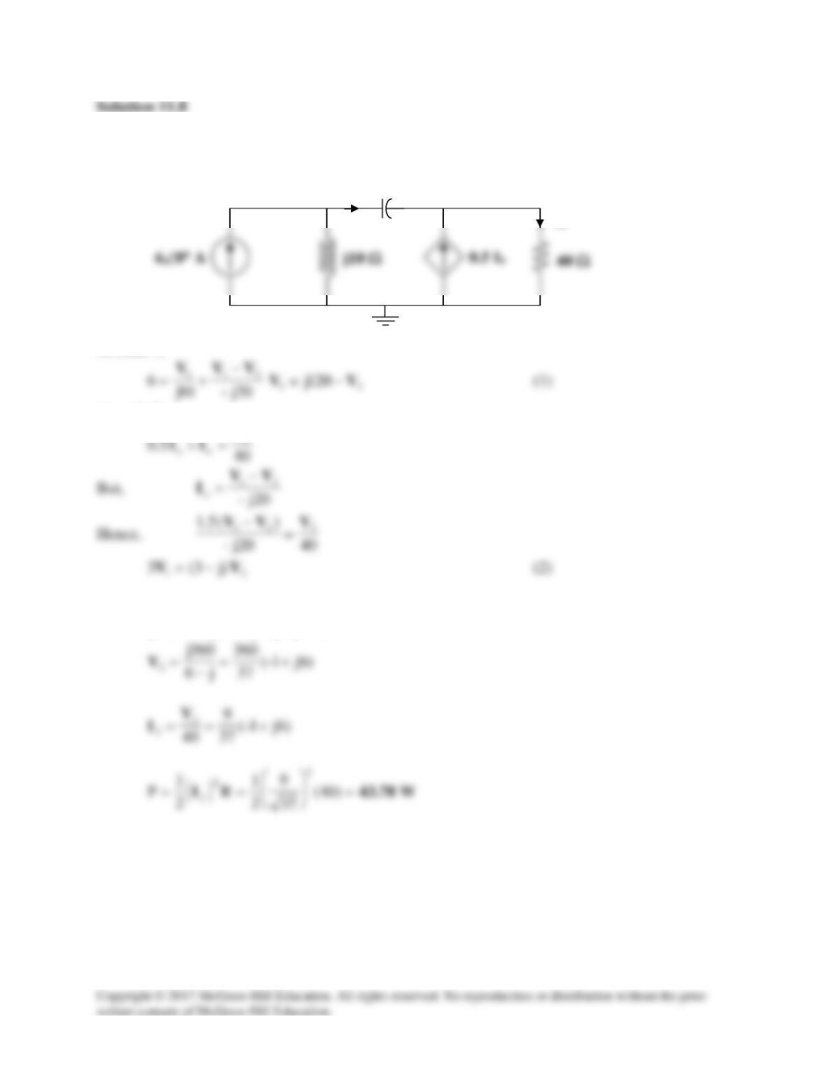
Solution 11.10
Solution 11.11
377=ω
,
4
10R =
,
-9
10200C ×=
Solution 11.2
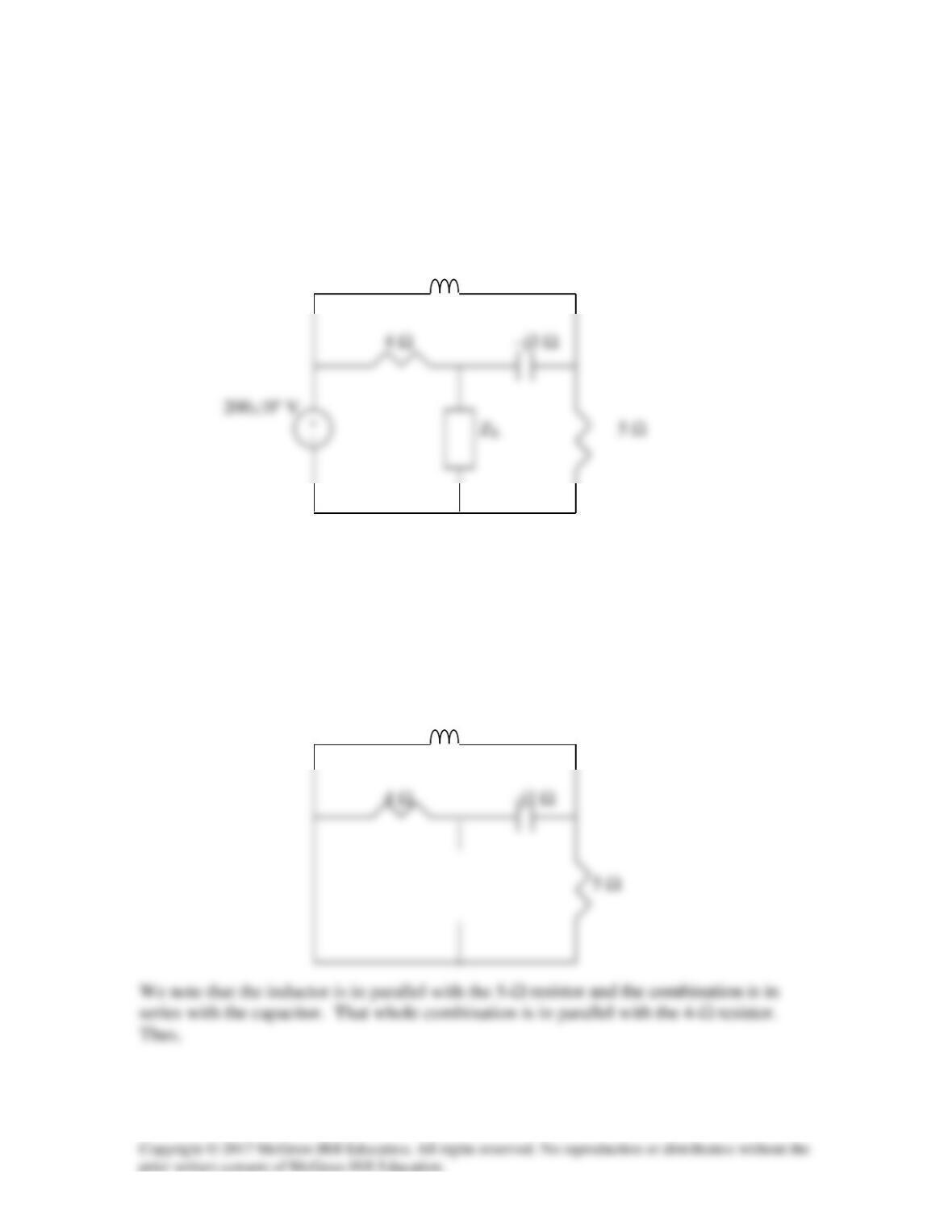
For the circuit shown in Fig. 11.44, determine the load impedance ZL for maximum
power transfer (to ZL). Calculate the maximum power absorbed by the load.
2j
Ω
Figure 11.44
For Prob. 11.12.
Solution
We find the Thevenin impedance using the circuit below.
2j
Ω
+−
2xj5
3j4
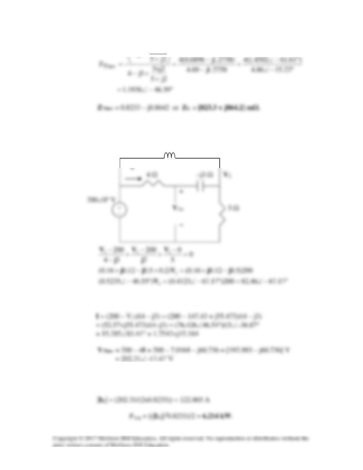
We obtain VTh using the circuit below. We apply nodal analysis.
2j
Ω
Thus, V2 = 157.52∠–20.62˚V = 147.43–j55.473
To calculate the maximum power to the load, we can use eq. 11.14,
IL = VTHEV/(2rl), to obtain,

Solution 11.13
For maximum power transfer to the load, ZL = [120 – j60] Ω.
Solution 11.14
Using Fig. 11.45, design a problem to help other students to better understand maximum
average power transfer to a load Z.
L
Figure 11.45
For Prob. 11.14.
might pose and solve the problem.
Problem Statement
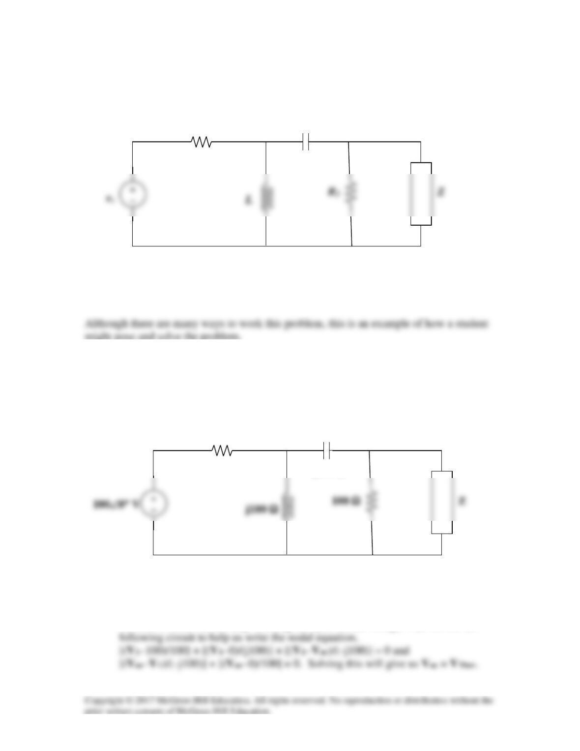
It is desired to transfer maximum power to the load Z in the circuit shown below. Find Z
and the maximum average power. Let vs = 100 sin(100t) V.
Solution
Step 1. We need to find the Thevenin equivalent at the terminals of Z. In order to do this
we need to find Voc and Zeq. Finding the open circuit voltage, Voc, we use the
100 Ω
–j100 Ω
R1
C
100 Ω
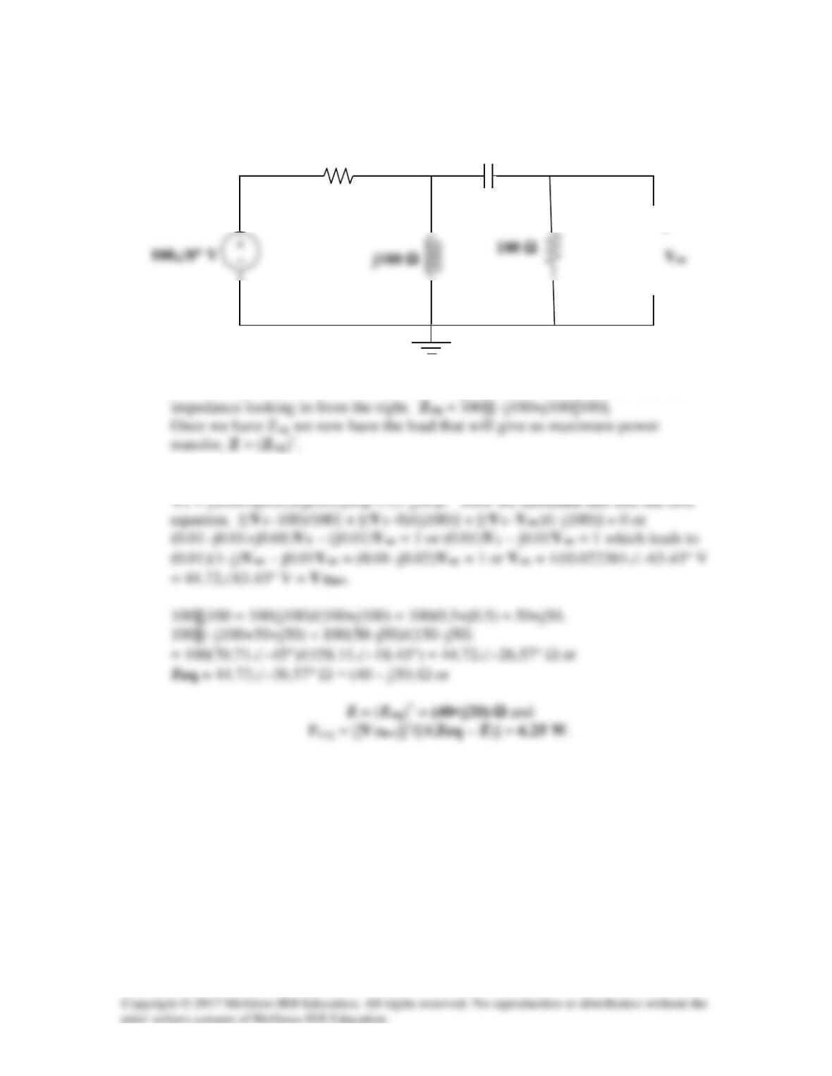
To find Zeq all we need to do is set the voltage source to zero and then find the
Step 2. [(Voc–V1)/(–j100)] + [(Voc–0)/100] = 0 or j0.01V1 = (0.01+j0.01)Voc or
100 Ω
–j100 Ω
+
−
V1
Solution 11.15
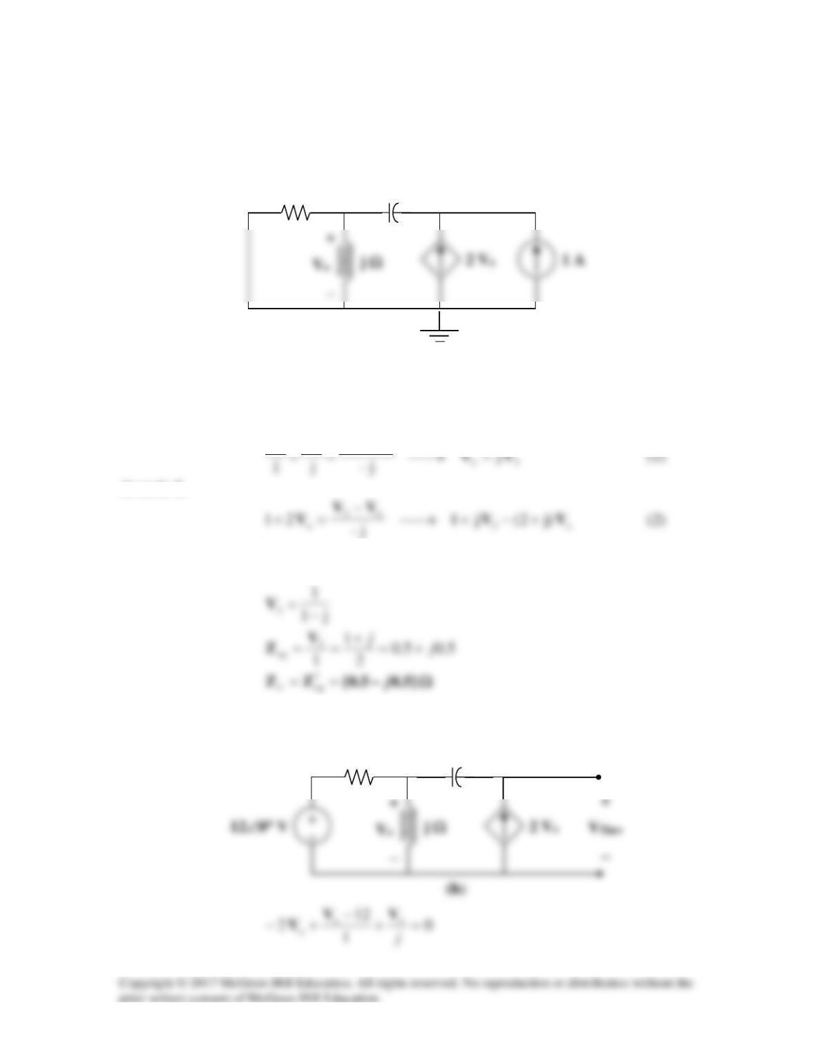
To find
eq
Z
, insert a 1-A current source at the load terminals as shown in Fig. (a).
At node 1,
o2oo j
VVVV =→
−
At node 2,
Substituting (1) into (2),
222 )j1()j)(j2(j1 VVV −=+−=
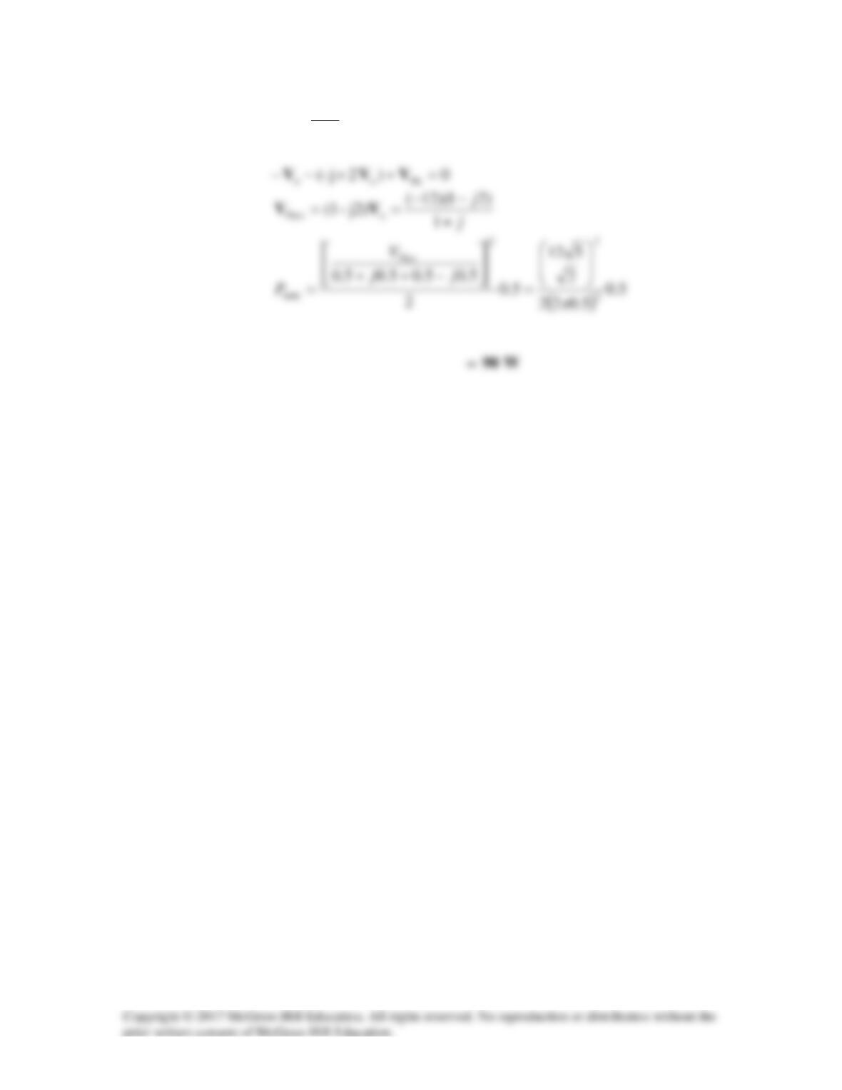
We now obtain
Thev
V
from Fig. (b).
–j Ω
1 Ω
1
2
(a)
–j Ω
1 Ω
j1
12–
o+
=V
Solution 11.16
For the circuit in Fig. 11.47, find the maximum power that can be delivered to the load
ZL.
Figure 11.47
For Prob. 11.16.
Solution
We find the Thevenin equivalent at the terminals of ZL. To find VThev, we use the circuit
shown below.
0.5Vo
At node 1,