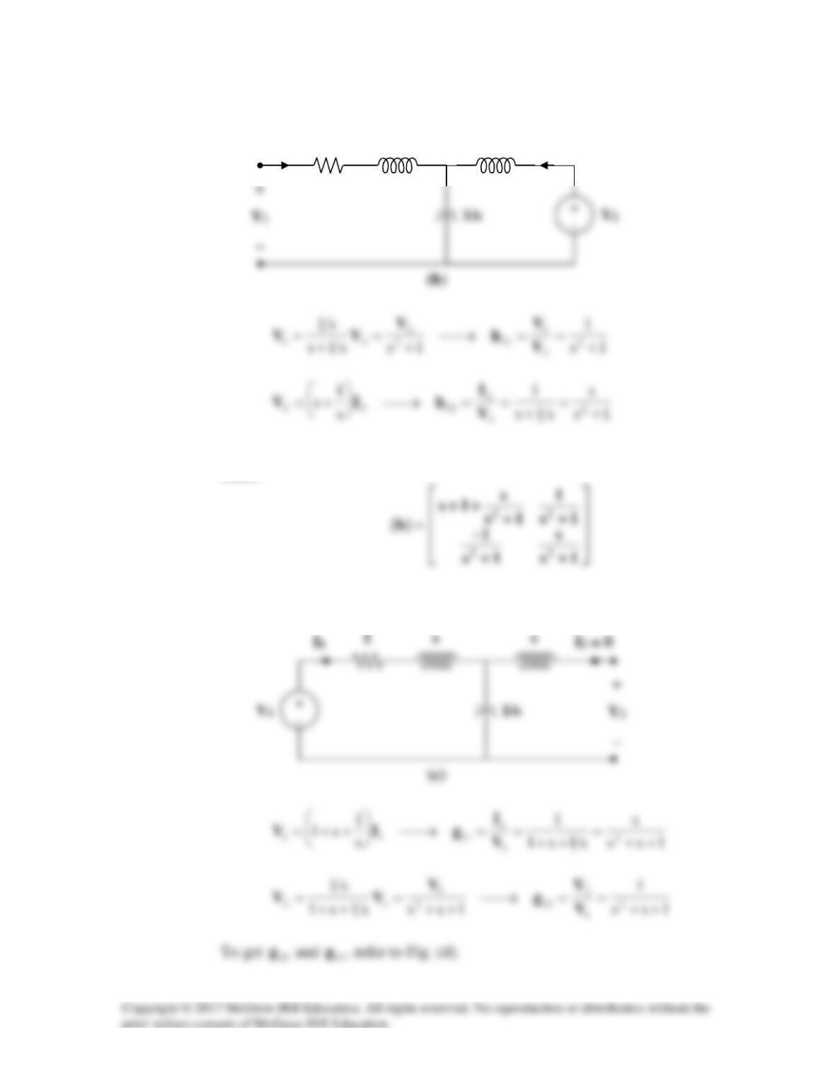
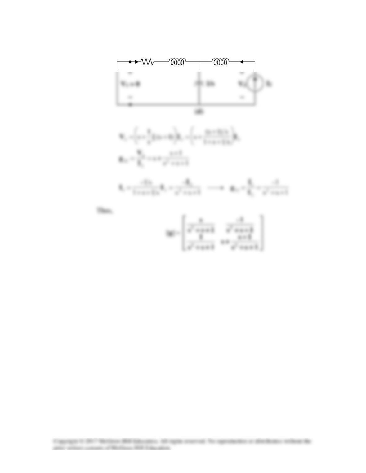
Alternatively, from the given circuit,
Comparing these with the equations for the h parameters show that
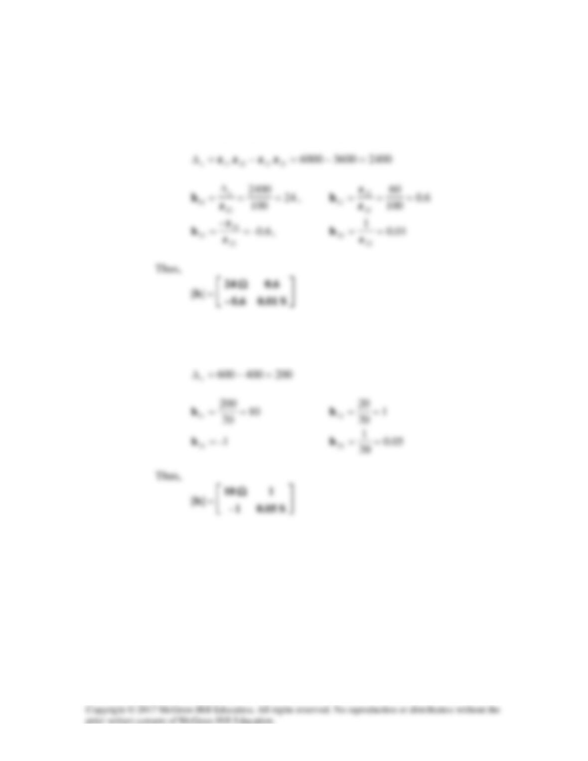
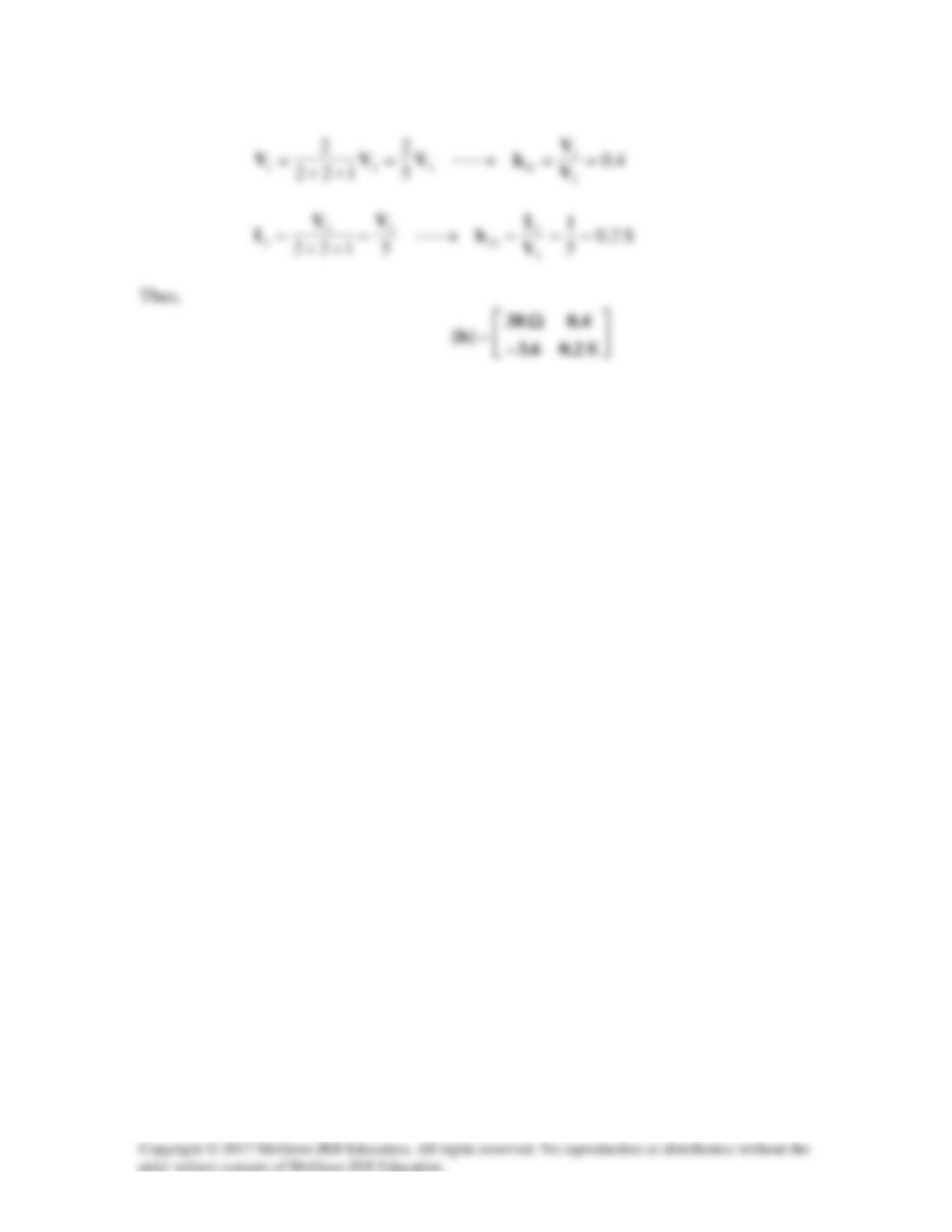
Using Table 18.1,
Solution 19.28
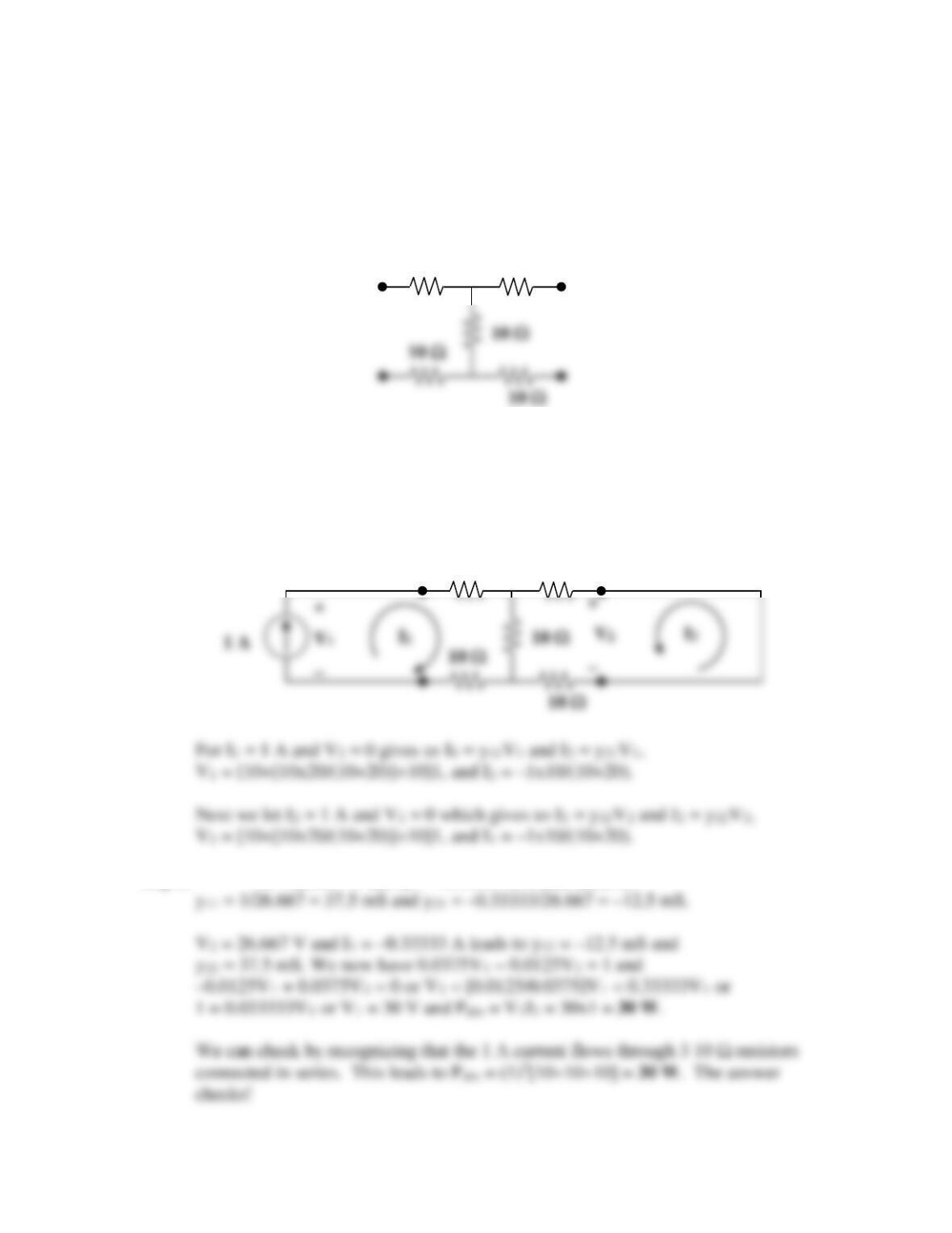
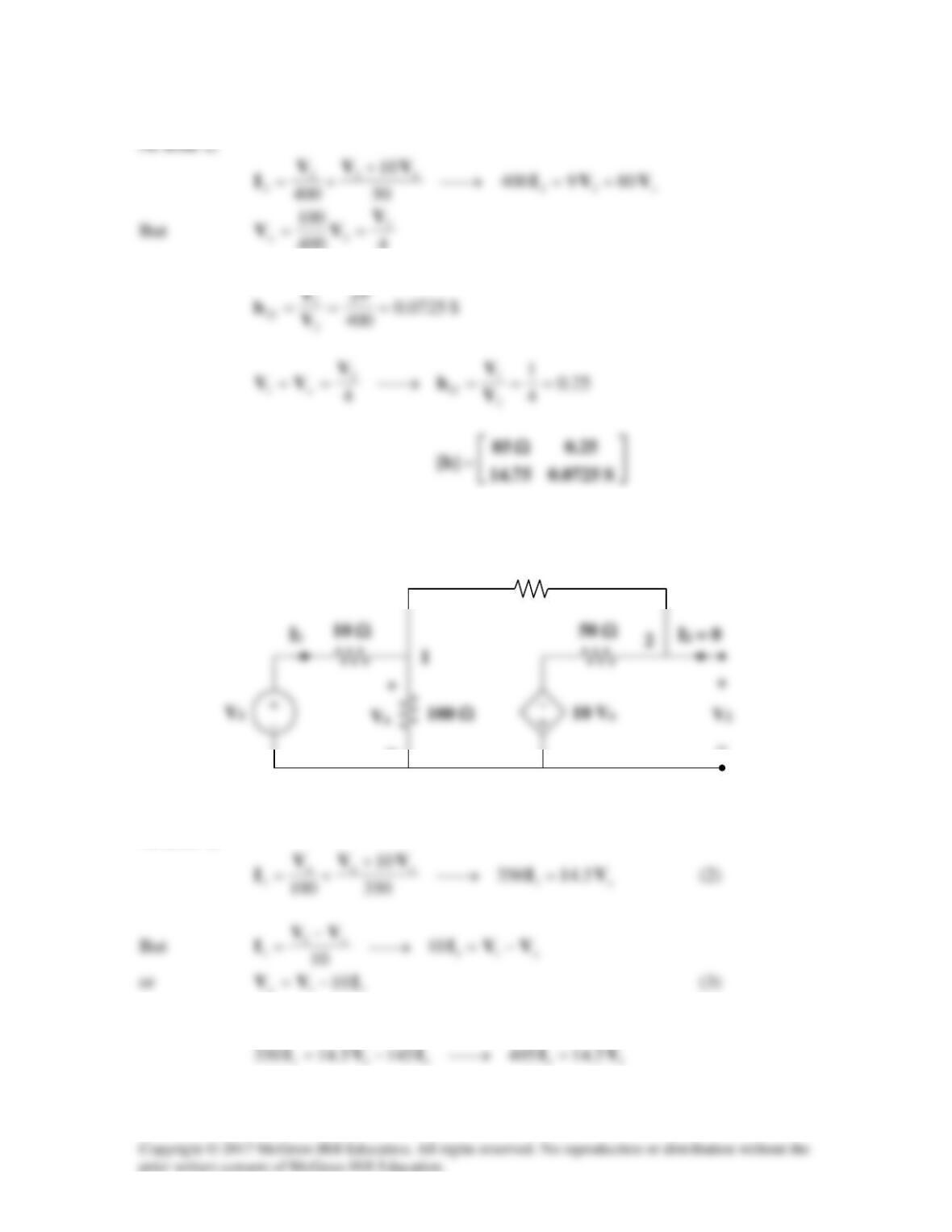
In the circuit of Fig.19.65, the input port is connected to a 1-A dc current source and the
right hand side of the circuit is left open (I2 = 0). Calculate the power absorbed by the
circuit by using the y parameters. Confirm your result by direct circuit analysis.
Figure 19.65 For Probs. 19.1 and 19.28.
Solution
Step 1. We obtain
11
y
and
21
y
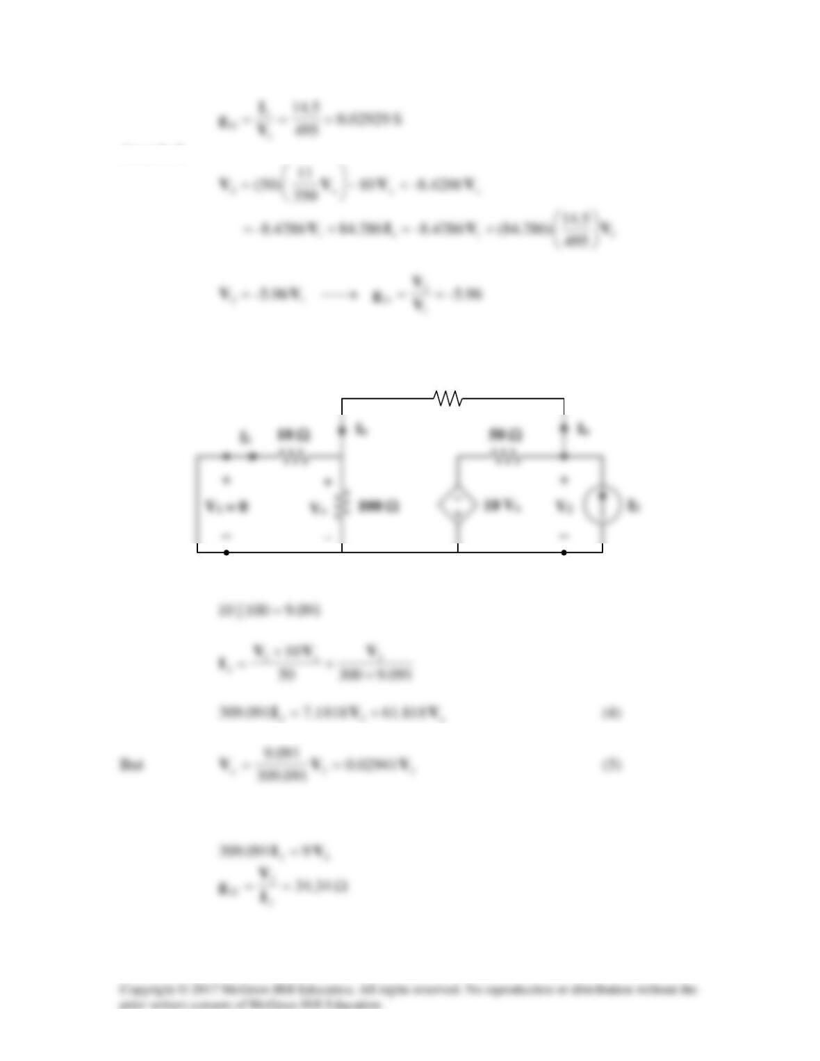
by considering the circuit in Fig.(a) and using
these equations. y11V1 + y12V2 = I1 and y21V1 + y22V2 = I2.
10 Ω
10 Ω
Step 2. V1 = 26.667 V and I2 = –0.33333 A which leads to
10 Ω
10 Ω
10 Ω
10 Ω
10 Ω
10 Ω
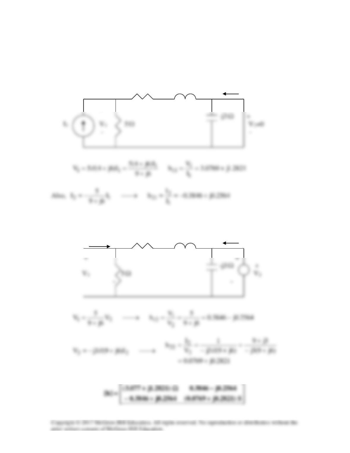
Solution 19.29
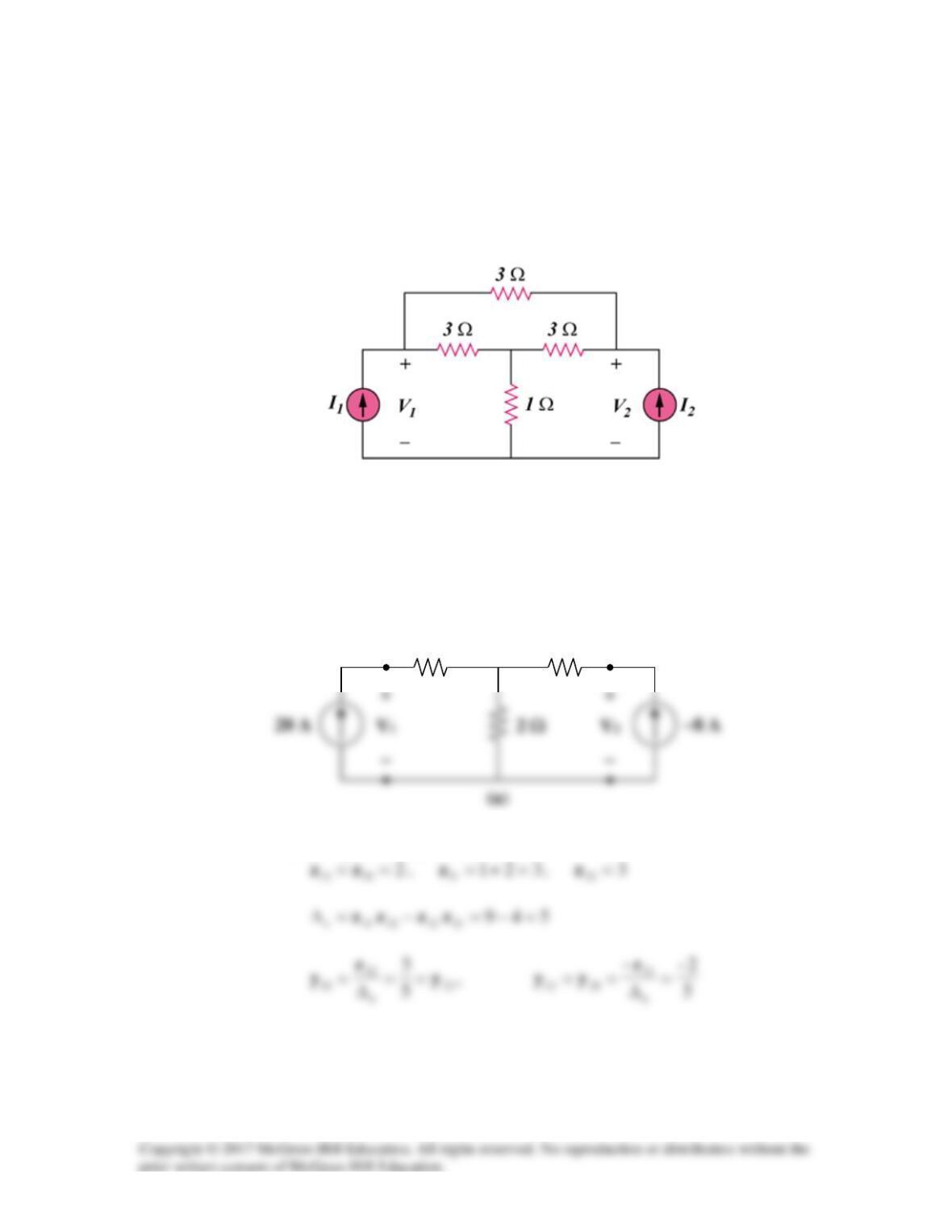
In the bridge circuit of Fig.19.87, I1 = 20 A and I2 = –8 A.
a) Find V1 and V2 using y parameters.
b) Confirm the results in part (a) by direct circuit analysis.
Figure 19.87
For Prob. 19.29.
Solution
(a) Transforming the ∆ subnetwork to Y gives the circuit in Fig. (a).
It is easy to get the z parameters
1 Ω
1 Ω
Vo
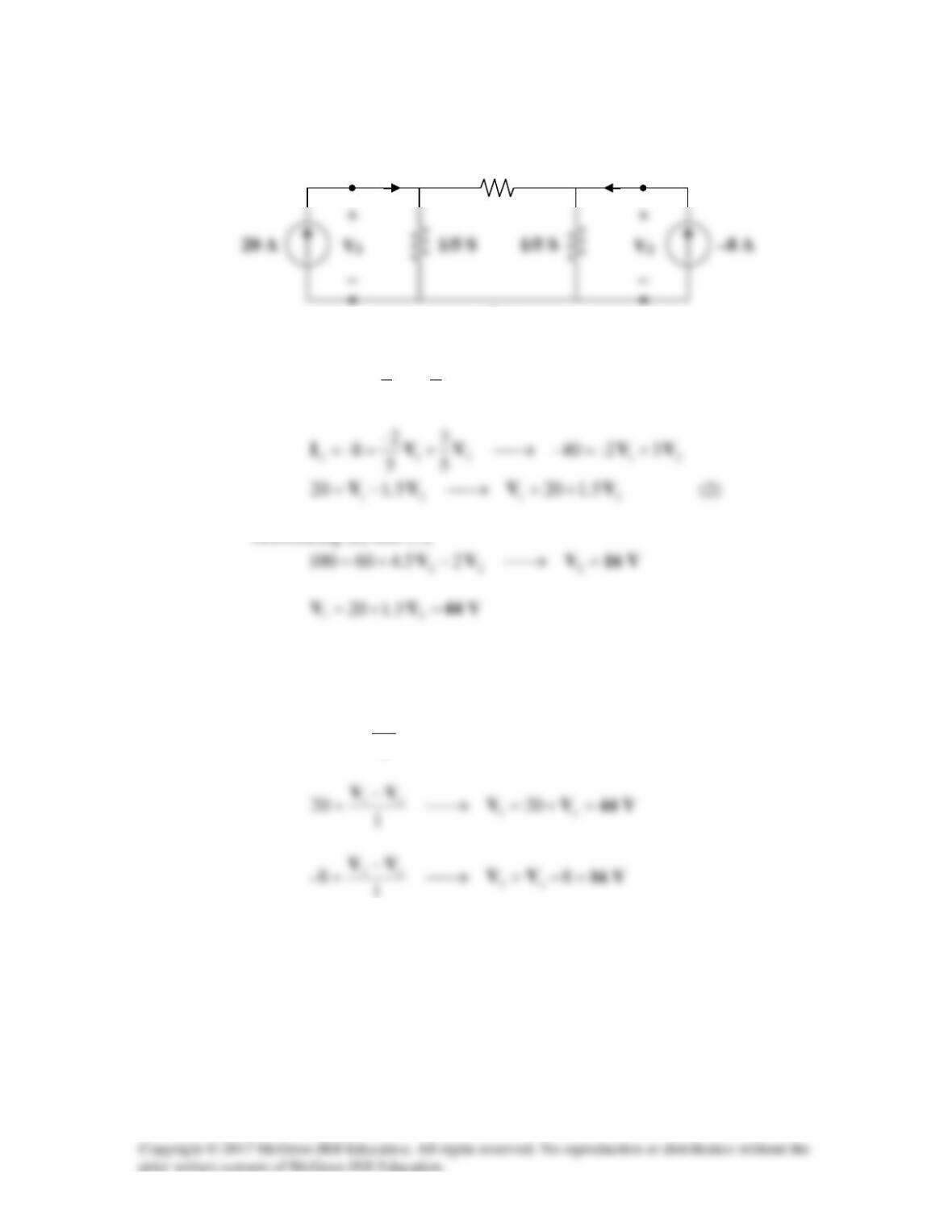
Thus, the equivalent circuit is as shown in Fig. (b).
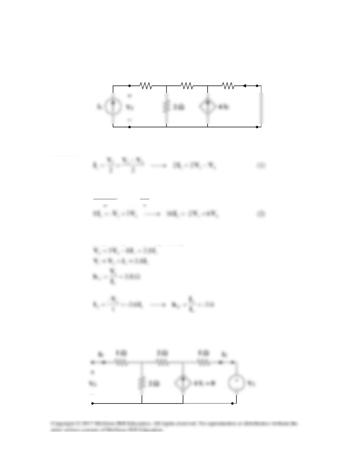
21211
23100
5
2
5
3
20 VVVVI −=→−==
(1)
Substituting (2) into (1),
(b) For direct circuit analysis, consider the circuit in Fig. (a).
For the main non-reference node,
24
2
820 =→=−
o
o
V
V
20 A
2/5 S
(b)
I1
I2
Solution 19.30
(a) Convert to z parameters; then, convert to h parameters using Table 18.1.
Ω=== 60
211211 zzz
,
Ω= 100
22
z
(b) Similarly,
Ω= 30
11
z
Ω=== 20
222112
zzz
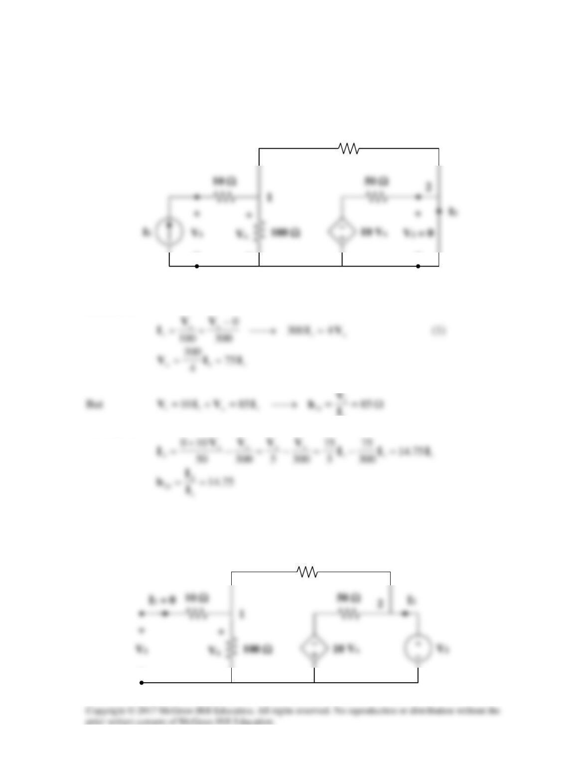
Solution 19.31
We get
11
h
and
21
h
by considering the circuit in Fig. (a).
At node 1,
At node 2,
4
4
1
43
V
I
VV =+
−
Adding (1) and (2),
To get
22
h
and
12
h
, refer to the circuit in Fig. (b). The dependent current source can be
replaced by an open circuit since
04
1
=I
.
1 Ω
1 Ω
V3
V4
(a)
2 Ω
I2
2 Ω
(b)
−
Solution 19.32
Using Fig. 19.90, design a problem to help other students to better understand how to find
the h and g parameters for a circuit in the s-domain.
Although there are many ways to solve this problem, this is an example based on the
same kind of problem asked in the third edition.
Problem
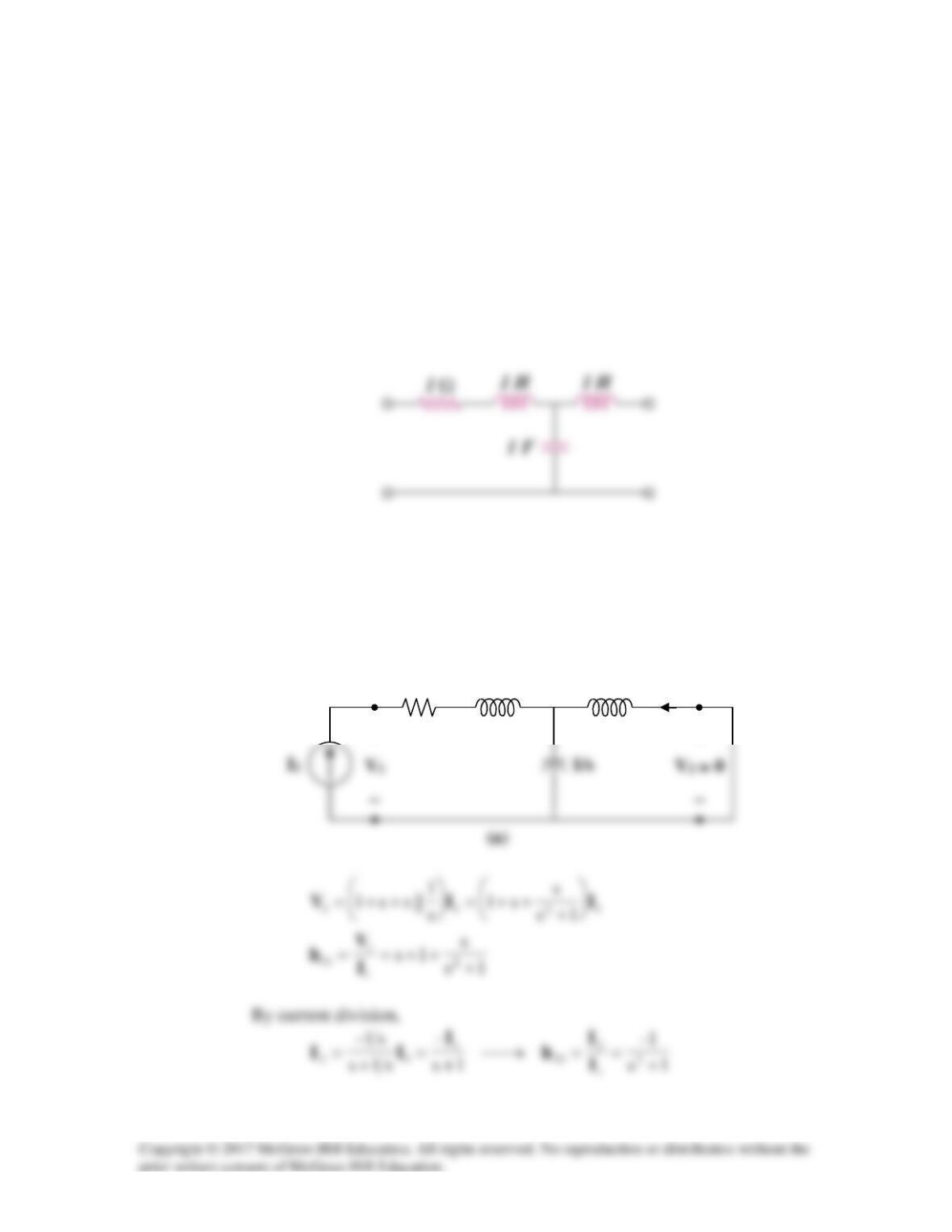
Find the h and g parameters of the two-port network in Fig.19.90 as functions of s.
Figure 19.90
Solution
(a) We obtain
11
h
and
21
h
by referring to the circuit in Fig. (a).
s
1
I2
+
+
s
To get
22
h
and
12
h
, refer to Fig. (b).
Thus,
(b) To get
11
g
and
21
g
, refer to Fig. (c).
s
1
s
s
1
I2
s
I1 = 0
s
1
s
I2
I
1
Solution 19.33
To get h11 and h21, consider the circuit below.
4
Ω
j6
Ω
I2
+
Ω
To get h22 and h12, consider the circuit below.
4
Ω
j6
Ω
I2
I1
Ω
Ω
Thus,
Solution 19.34
Refer to Fig. (a) to get
11
h
and
21
h
.
At node 1,
1
I
At node 2,
To get
22
h
and
12
h
, refer to Fig. (b).
−
−
−
300 Ω
(a)
−
−
300 Ω
(b)
4400
Hence,
2222 29209400 VVVI =+=
To get
11
g
and
21
g
, refer to Fig. (c).
At node 1,
11x 10 IVV −=
Substituting (3) into (2) gives
−
−
300 Ω
(c)
At node 2,
To get
22
g
and
12
g
, refer to Fig. (d).
Substituting (5) into (4) gives
300 Ω
(d)
091.309
34.34
091.309
22
o
IV
I==
Solution 19.35
To get
11
h
and
21
h
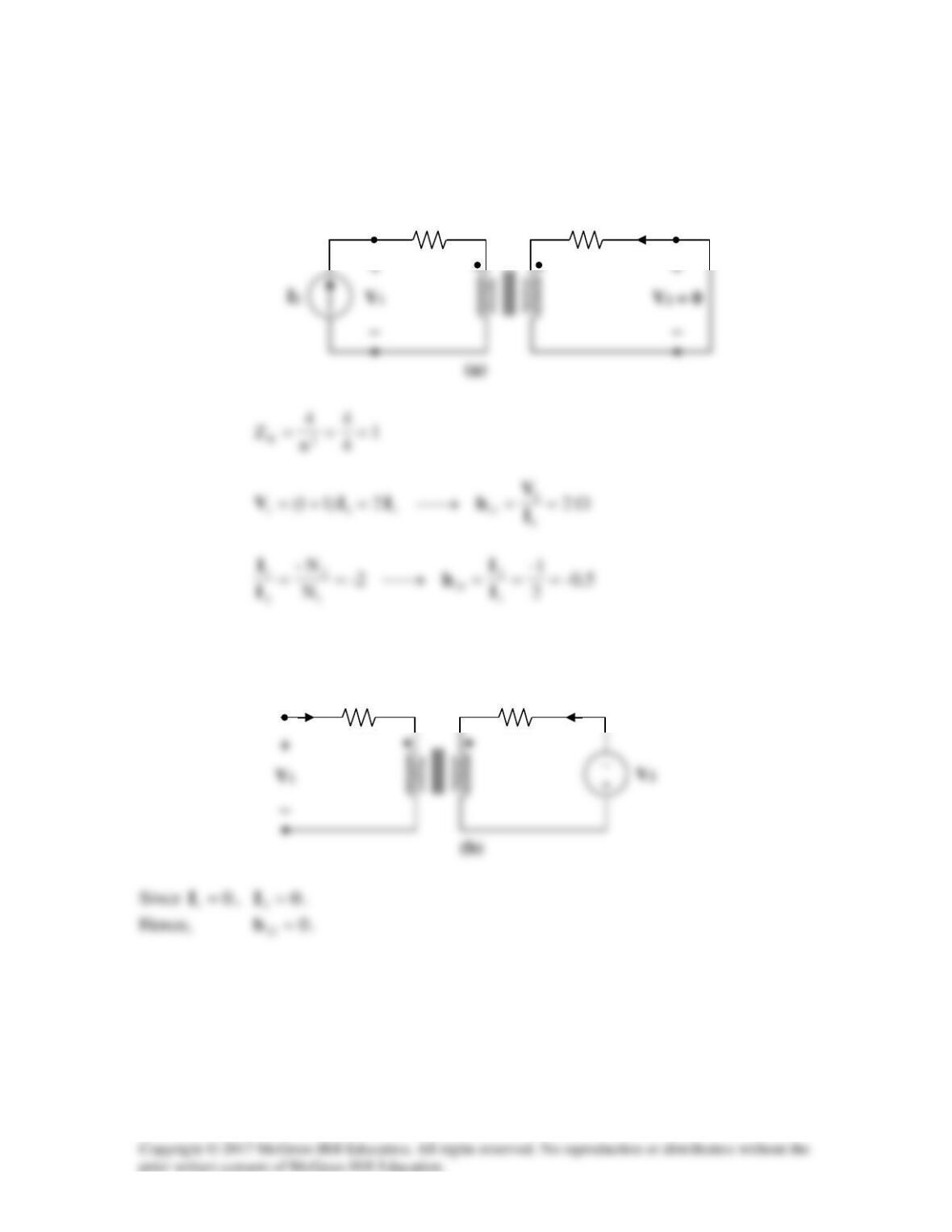
consider the circuit in Fig. (a).
To get
22
h
and
12
h
, refer to Fig. (b).
4 Ω
1 Ω
I2
1 : 2
4 Ω
1 Ω
I2
1 : 2
I1 = 0
At the terminals of the transformer, we have
1
V
and
2
V
which are related as
Solution 19.36
We replace the two-port by its equivalent circuit as shown below.
Ω= 2025||100
14
1
1=I
,
14
40
2
=V
2 I1
16 Ω
4 Ω
I1
I2
Solution 19.37
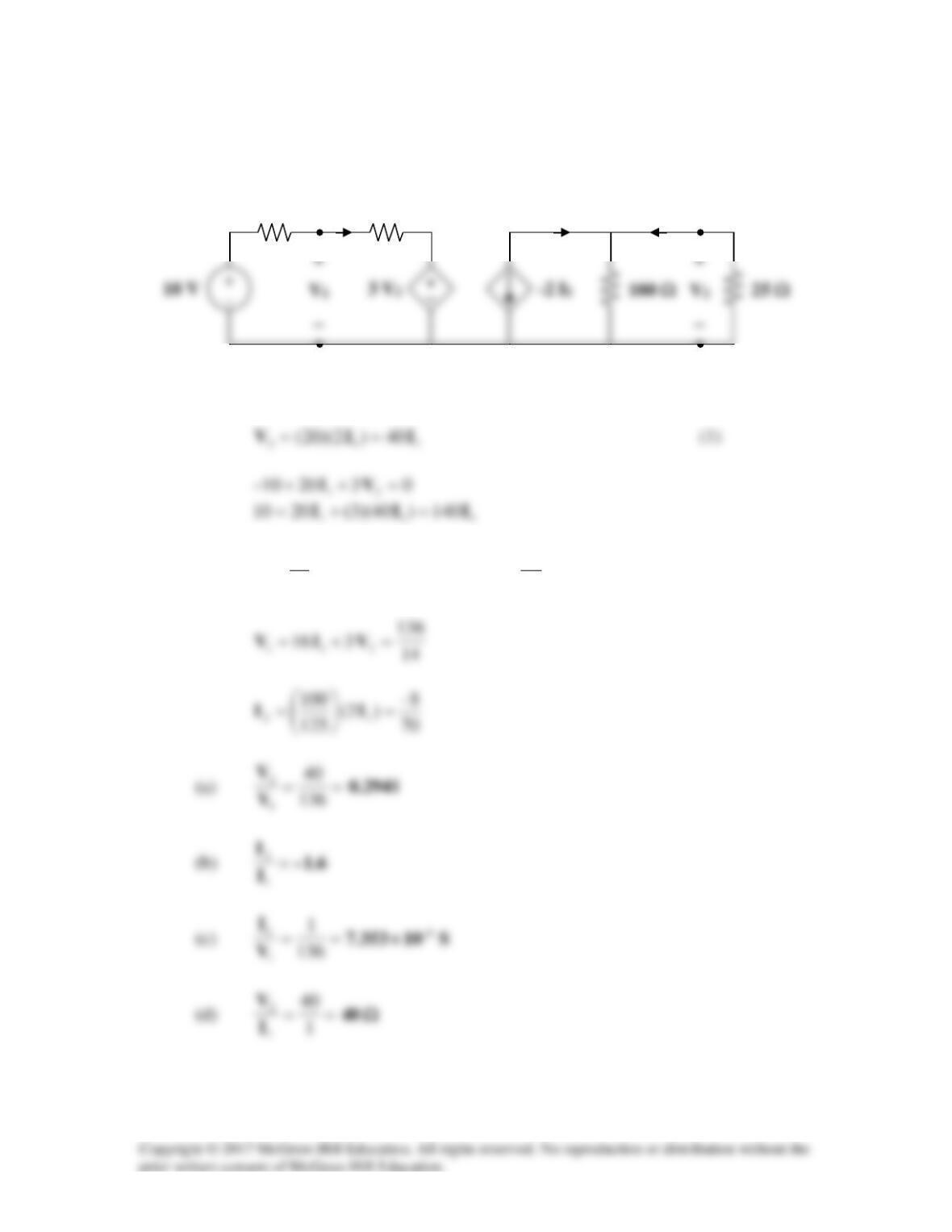
The input port of the circuit in Fig.19.79 is connected to a 10-V dc voltage source while
the output port is terminated by a 5-Ω resistor. Find the voltage across the 5-Ω resistor
by using h parameters of the circuit. Confirm your result by using direct circuit analysis.
Figure 19.79
For Probs. 19.18 and 19.37.
Solution
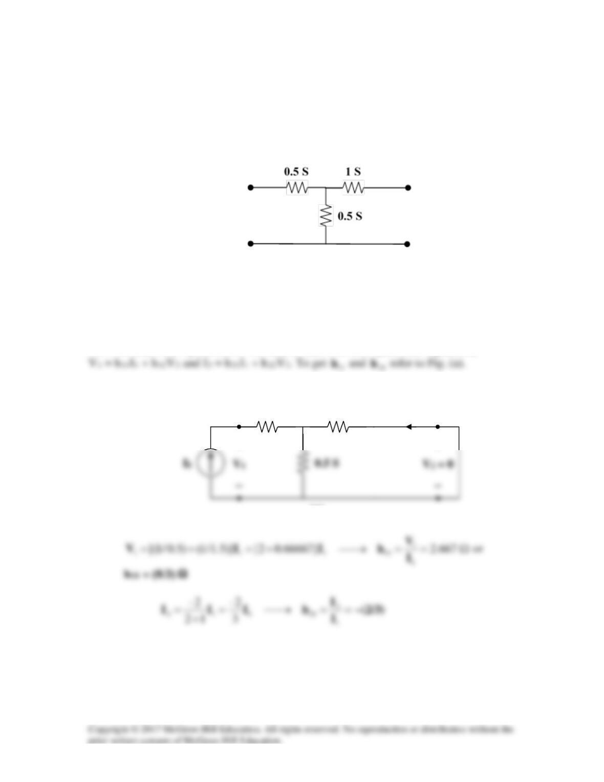
We first obtain the h parameters. We need to start with the h parameter equations,
1 S
+
0.5 S
(a)
I2
+
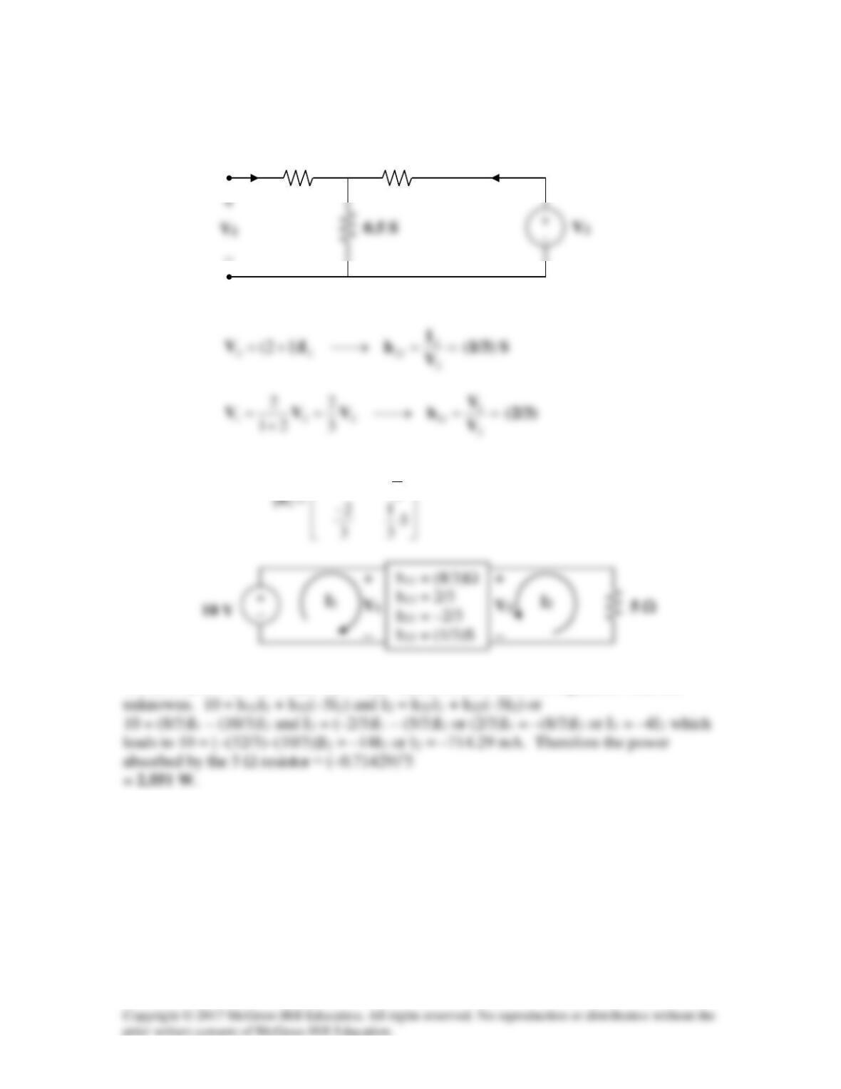
To get
22
h
and
12
h
, refer to the circuit in Fig. (b).
Ω
2
)3/8(
We now have V1 = 10 V and V2 = –5I2. Thus, we now have two equations with two
1 S
−
I1 = 0
0.5 S
(b)
I2