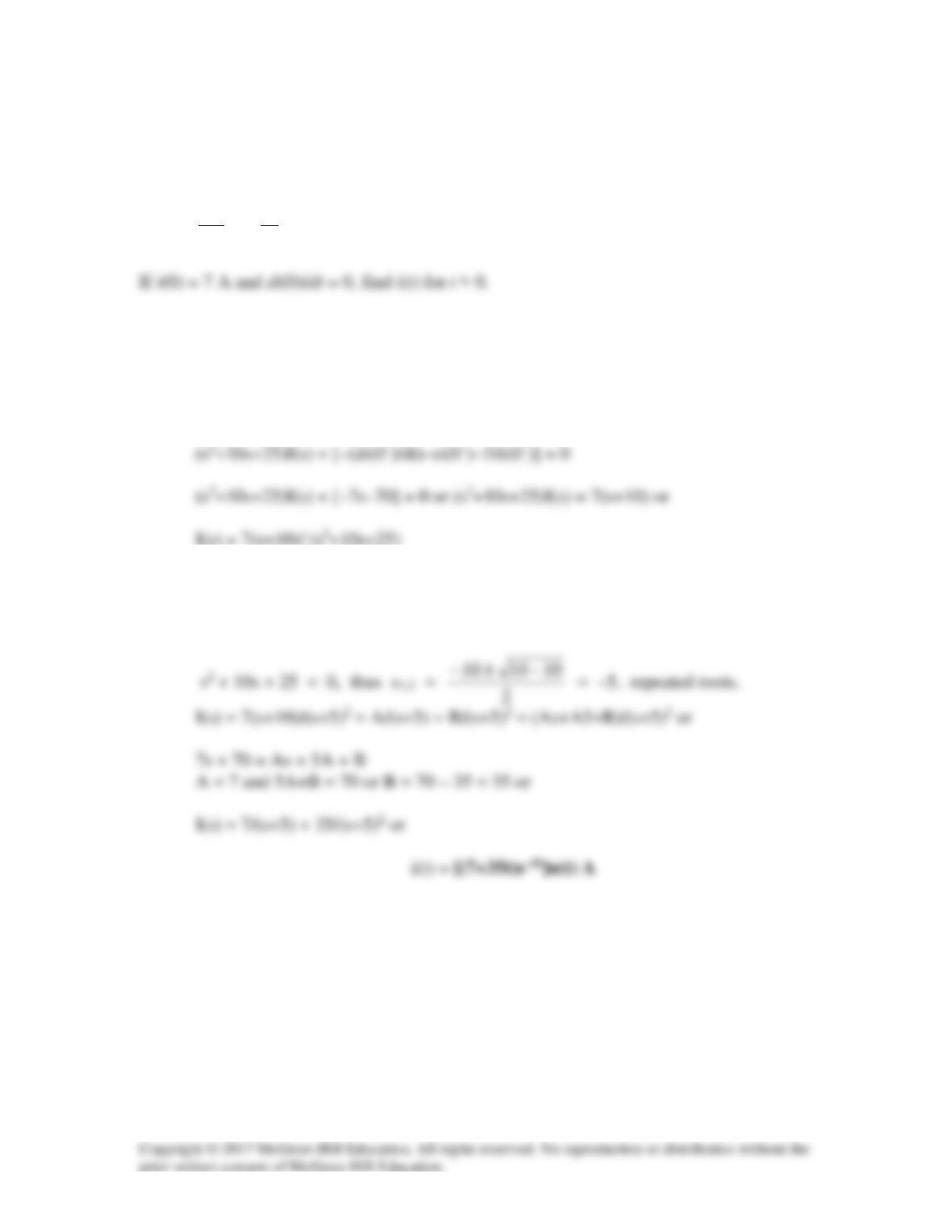
Solution 16.1
The current in an RLC circuit is described by
2
2
10 25 0
d i di i
dt dt
+ +=
Solution
Step 1. Transform the equation into the s-domain and solve for I(s).
s2I(s) – (di(0–)/dt) – si(0–) + 10sI(s) – 10i(0–) +25 I(s) = 0
Step 2. Perform a partial fraction expansion and then solve for i(t) in the time
domain.
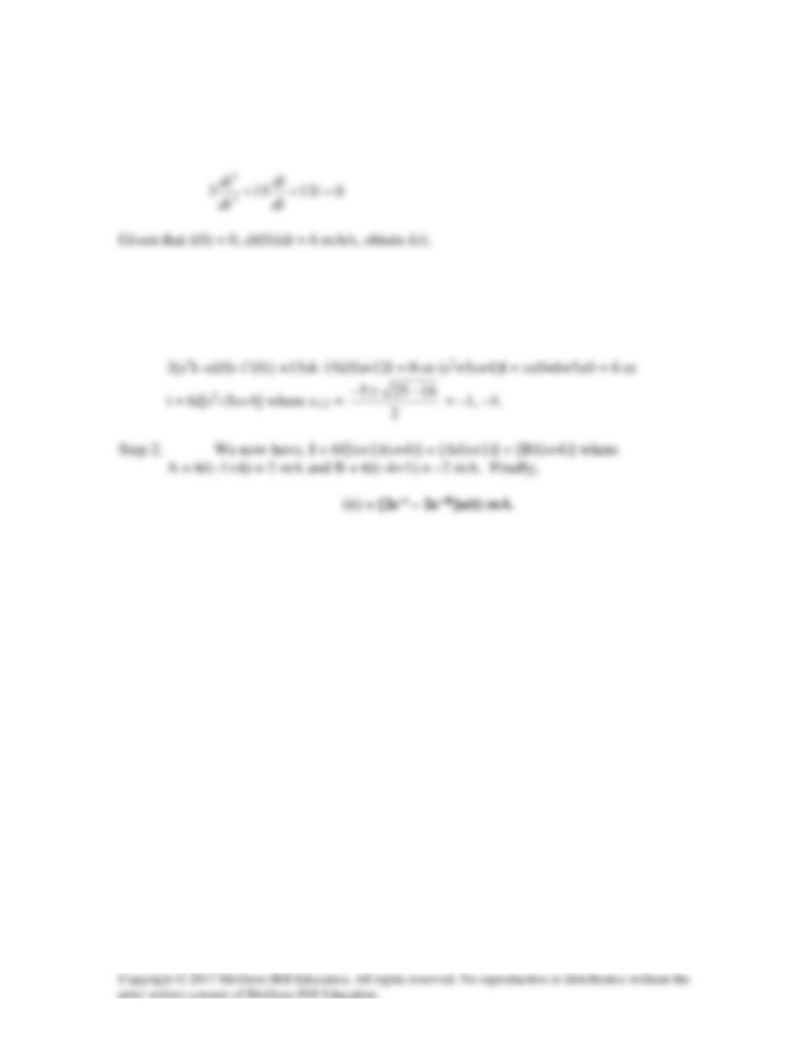
Solution 16.2
The differential equation that describes the current in an RLC network is
Solution
Step 1. Convert the equation into the s-domain and then solve for I(s) and then
perform a partial fraction expansion and then solve for i(t).
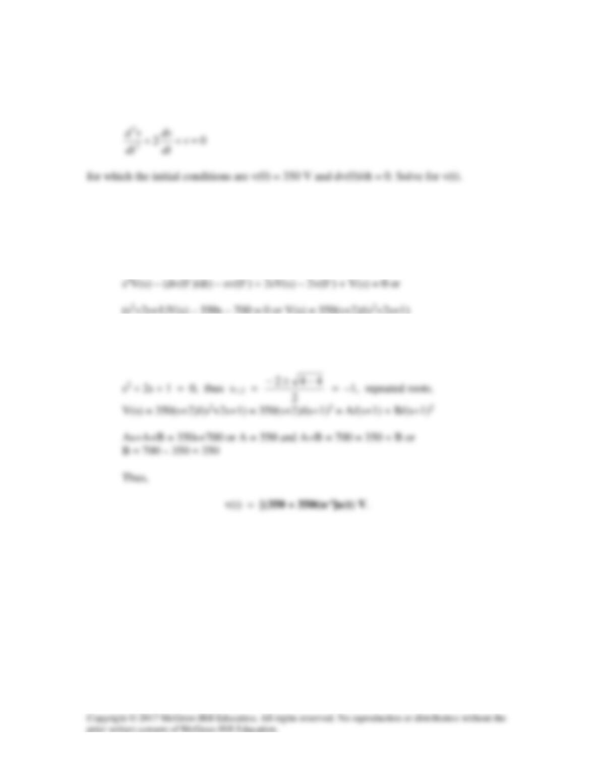
Solution 16.3
The natural response of an RLC circuit is described by the differential equation
Solution
Step 1. Transform the equation into the s-domain and solve for v(t).
Step 2. Perform a partial fraction expansion and solve for V(s). Inverse transform
into the time–domain and solve for v(t).
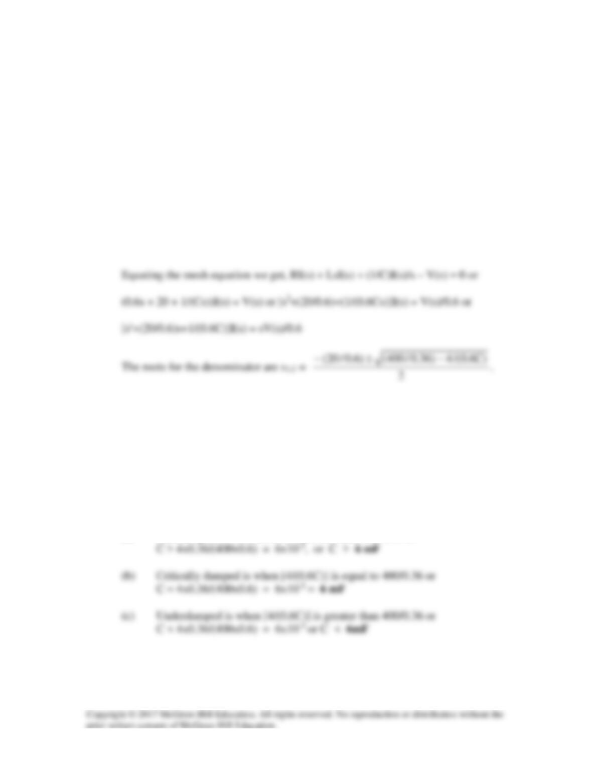
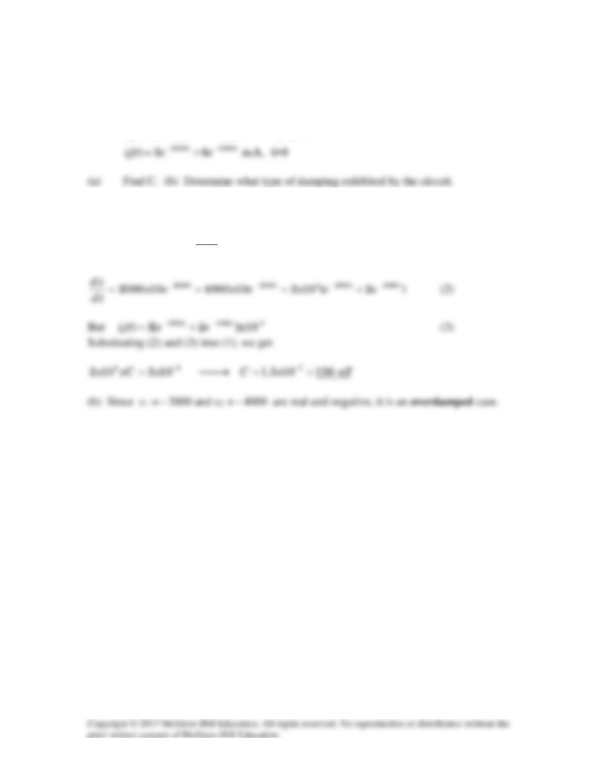
Solution 16.4
If R = 20 Ω, L = 0.6 H, what value of C will make an RLC series circuit:
(a) overdamped,
(b) critically damped,
(c) underdamped?
Solution
Step 1. Since we are working with a series RLC circuit, we can express our values
in terms of I(s) and the s equation that multiplies it in the s-domain. From here
we can easily find the values that produce over damped, critically damped, and
underdamped conditions.
Step 2. To find the values of our roots that produces overdamped, critically
damped, and underdamped conditions, we note that when s1 and s2 values that
produces these values,
overdamped is when s1 and s2 are real with no complex values
critically damped is when s1 = s2
underdamped is when both s1 and s2 have complex roots and s1 = s2*
Now all we need to do is to solve for these conditions.
(a) Overdamped is when [4/(0.6C)] is less than 400/0.36 or
Solution 16.5
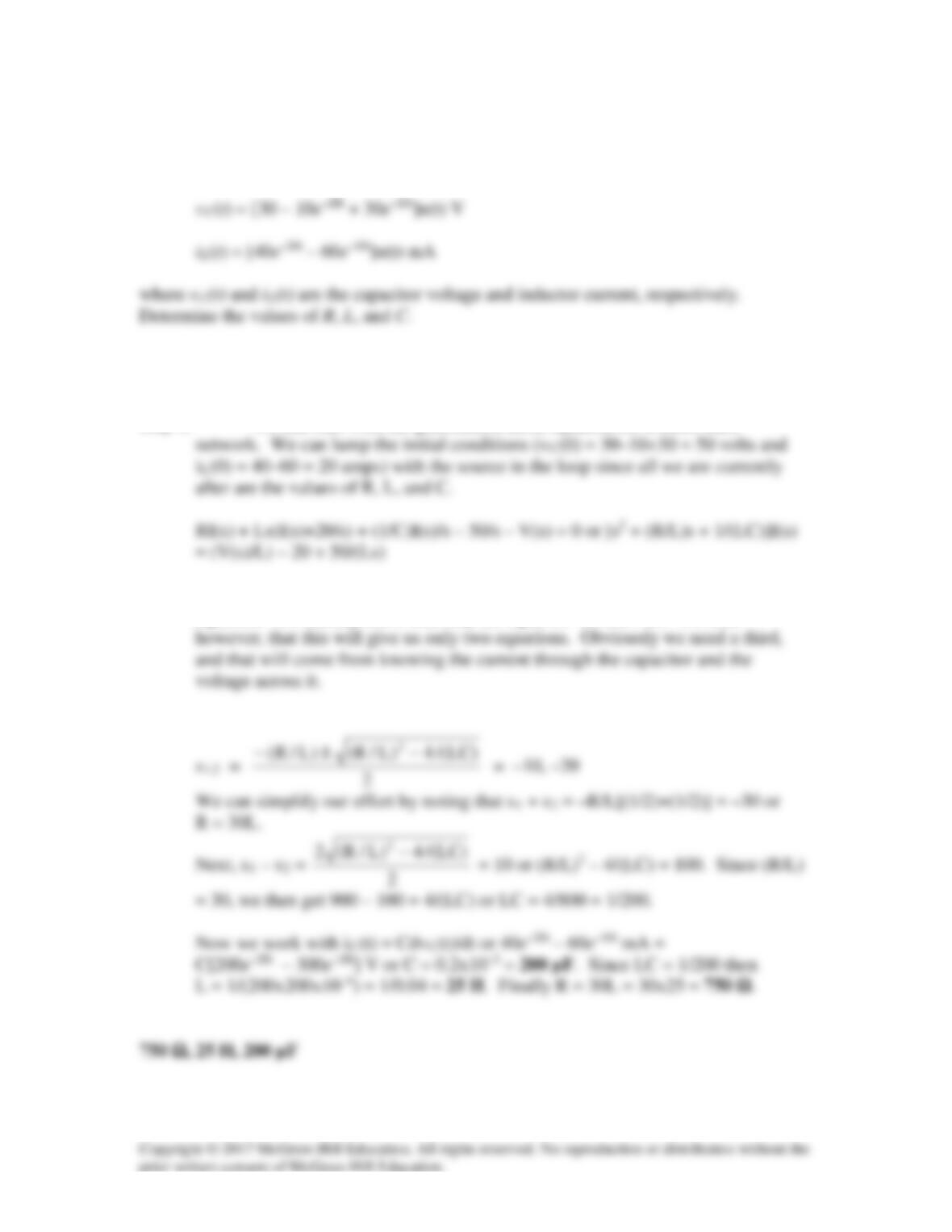
The responses of a series RLC circuit are
Solution
Step 1. We can start with the generalized mesh equation for a series RLC
Step 2. The values of R, L, and C will come from the roots of the denominator s
equation. We already know that they are equal to –10 and –20. We note
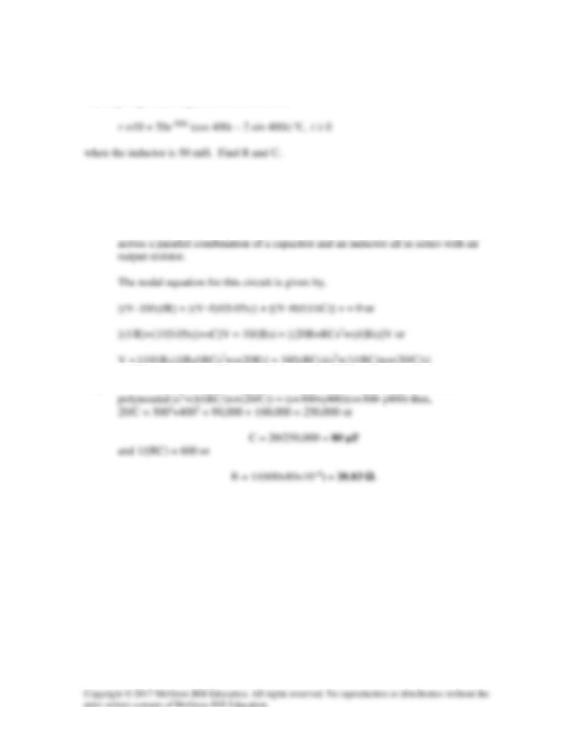
Solution 16.6
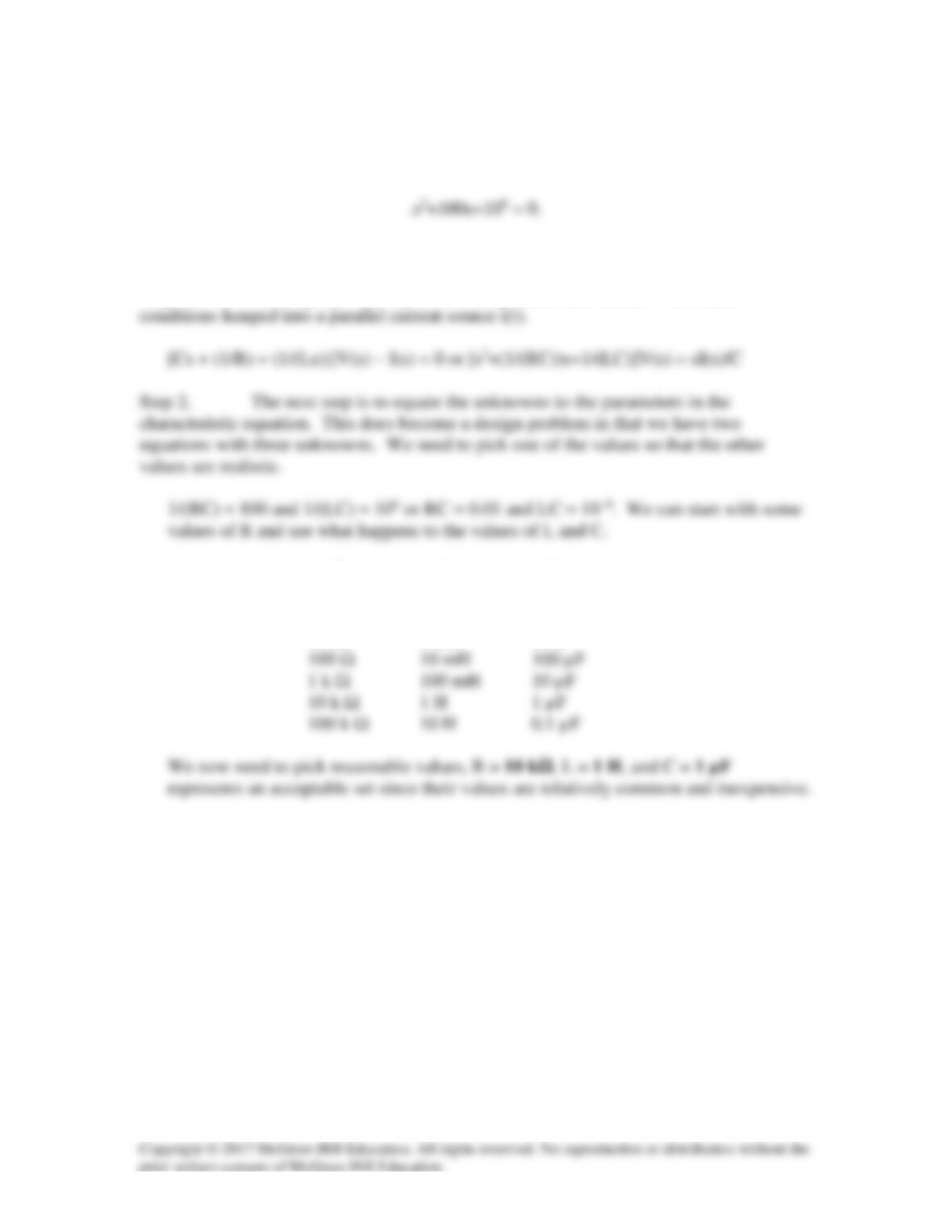
Design a parallel RLC circuit that has the characteristic equation
Solution
Step 1. Develop a general equation for a parallel RLC circuit with initial
R L C
1 Ω 100 µH 10 mF
10 Ω 1 mH 1 mF
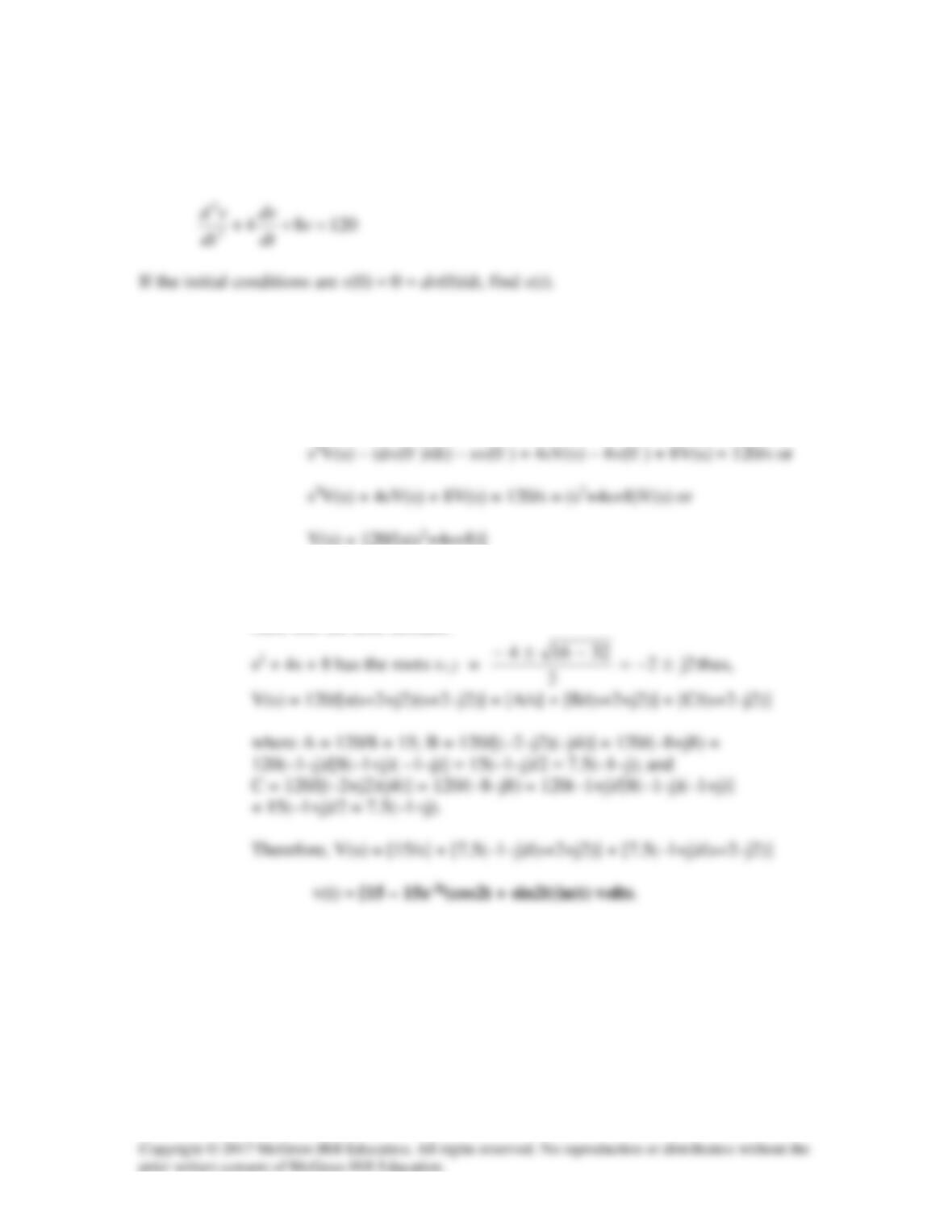
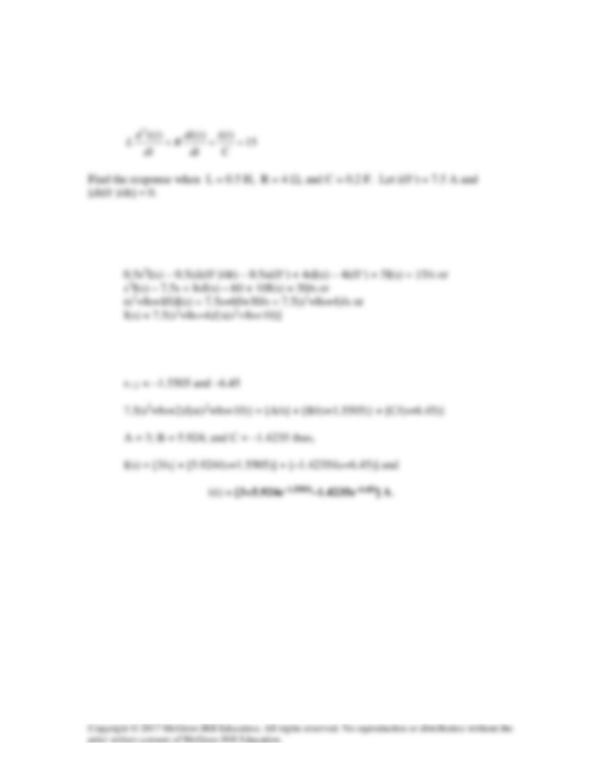
Solution 16.7
The step response of an RLC circuit is given by
Solution
Step 1. We start by transforming the equation into the s-domain. We then solve
for I(s).
s2I(s) – (di(0–)/dt) – si(0–) + 2sI(s) – 2i(0–) + 5 I(s) = 30/s or
Step 2. We need to find the roots of (s2+2s+5) and then perform a partial fraction
expansion and then transform back into the time domain and realize i(t).
s2 + 2s + 5, has the roots s1,2 =
2 4 20
−± −
= –1±j2
Solution 16.8
A branch voltage in an RLC circuit is described by
Solution
Step 1. First we transform the equation into the s–domain. Then we solve for
V(s).
Step 2. Now we need to solve for the roots of the denominator and perform a
partial fraction expansion. Then we can inverse transform the answer
back into the time domain.
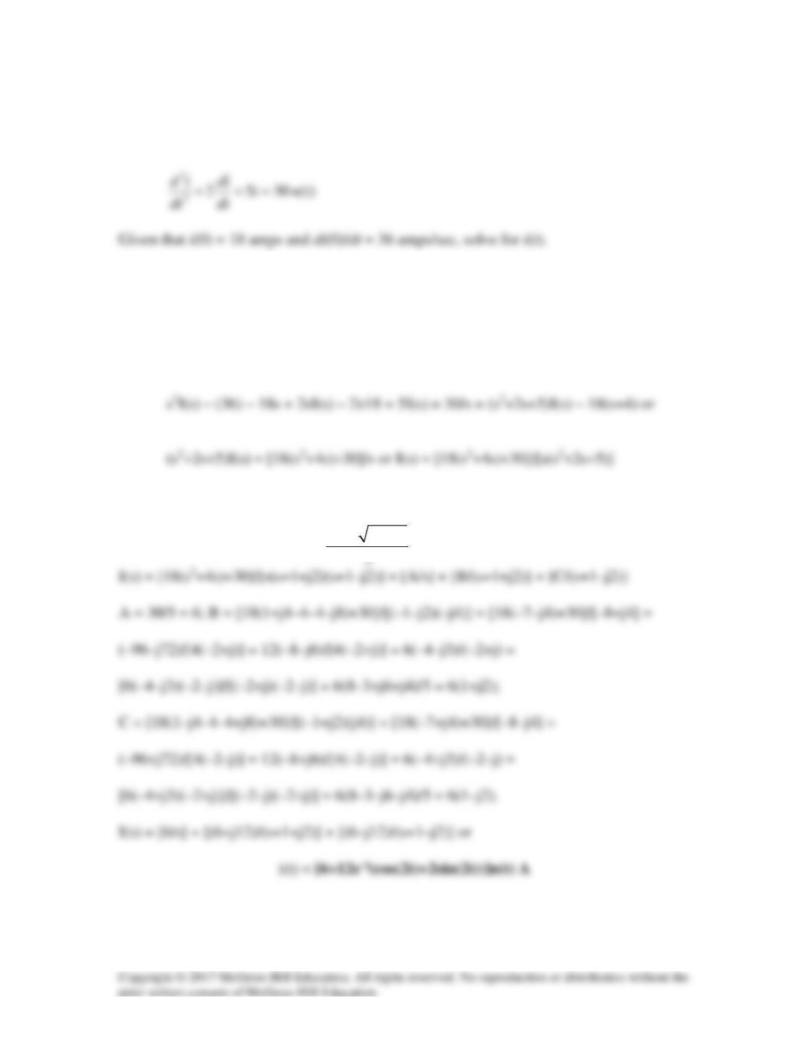
Solution 16.9
A series RLC circuit is described by
Solution
Step 1. First transform the equation into the s-domain. Then solve for I(s).
Step 2. Next we need to find the roots of (s2+8s+10) and then perform a partial
fraction expansion and then inverse transform back into the time domain.
Solution 16.10
The step responses of a series RLC circuit are
2000 4000
40 10 10 V, t>0
tt
v e e
−−
=−−
Solution
(a)
() ()
o
LC
d v
it it C
d t
= =
(1)
Solution 16.11
The step response of a parallel RLC circuit is
Solution
Step 1. There are different ways to approach this problem so, we will convert
everything into the s-domain and then solve for the unknowns. We should also
note that the steady-state voltage is 10 volts, then the circuit is a step input voltage
Step 2. From the value of v(t) we can determine the value of the roots of the
Solution 16.12
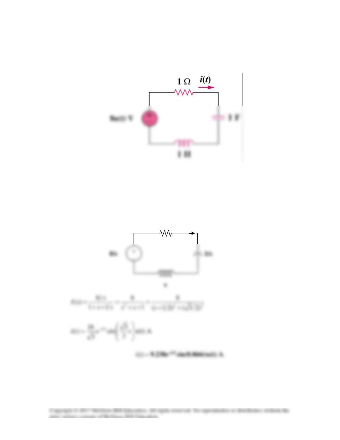
Determine i(t) in the circuit of Fig. 16.35 by means of the Laplace transform.
Figure 16.35
For Prob. 16.12.
Solution
Consider the s-domain form of the circuit which is shown below.
1
I(s)
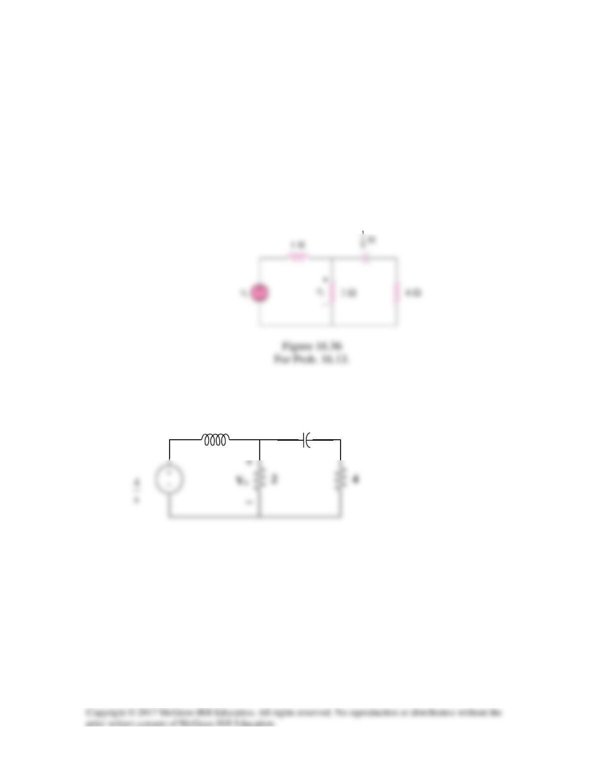
Solution 16.13
Using Fig. 16.36, design a problem to help other students to better understand circuit
analysis using Laplace transforms.
Although there are many ways to solve this problem, this is an example based on the
same kind of problem asked in the third edition.
Problem
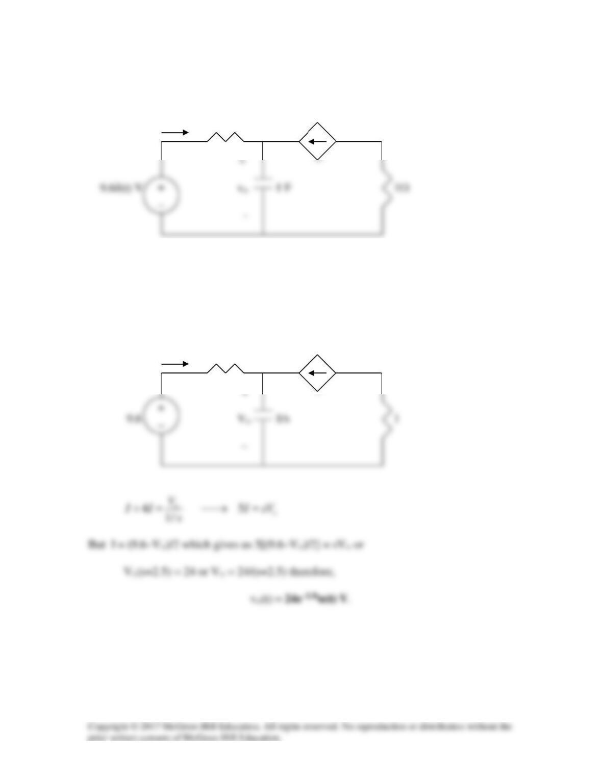
Find vx in the circuit shown in Fig. 16.36 given vs = 4u(t) V.
Solution
s
8/s
0VsV)s4s2(
s
)32s16(
)8s4(V
s
8
4
0V
2
0V
s
s
4
V
x
2
x
2
x
xx
x
=+++
+
−+=
+
−
+
−
+
−
Solution 16.14
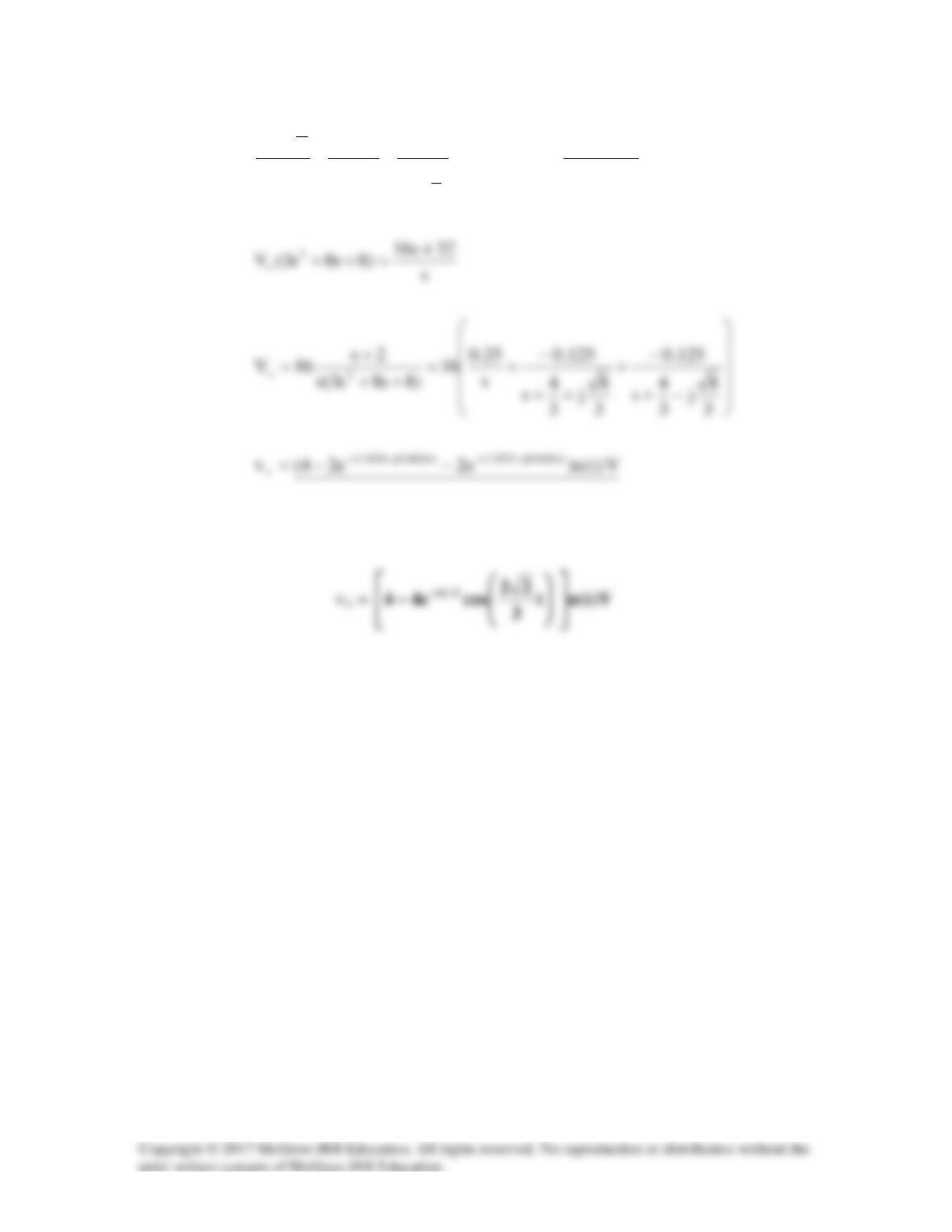
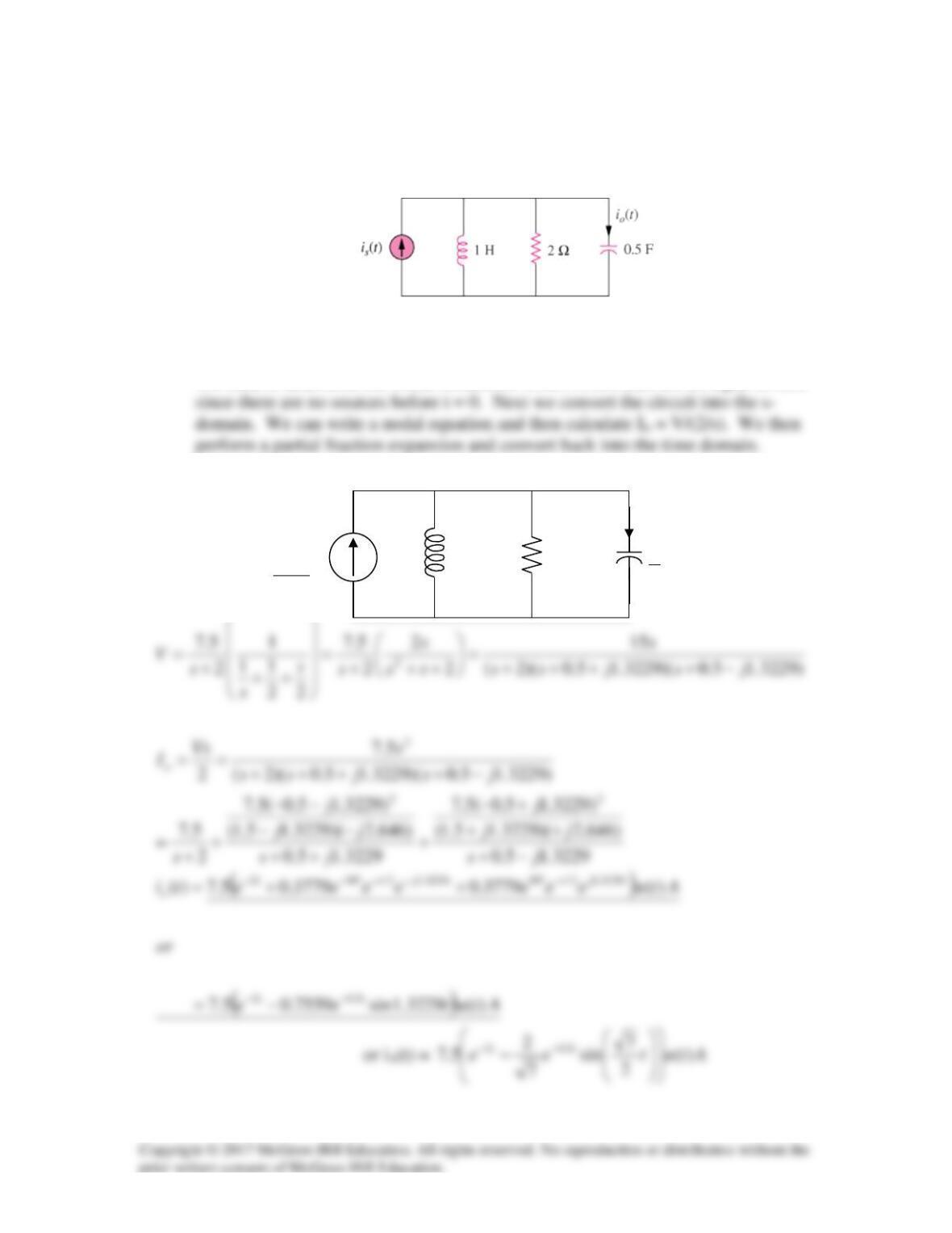
Find i(t) for t>0 for the circuit in Fig. 16.37. Assume is(t) = [6u(t) + 3δ(t)] mA.
1 Ω
i(t)
Figure 16.37
For Prob. 16.14.
Solution
In the s-domain, the circuit becomes that shown below.
1
2
1

Solution 16.15
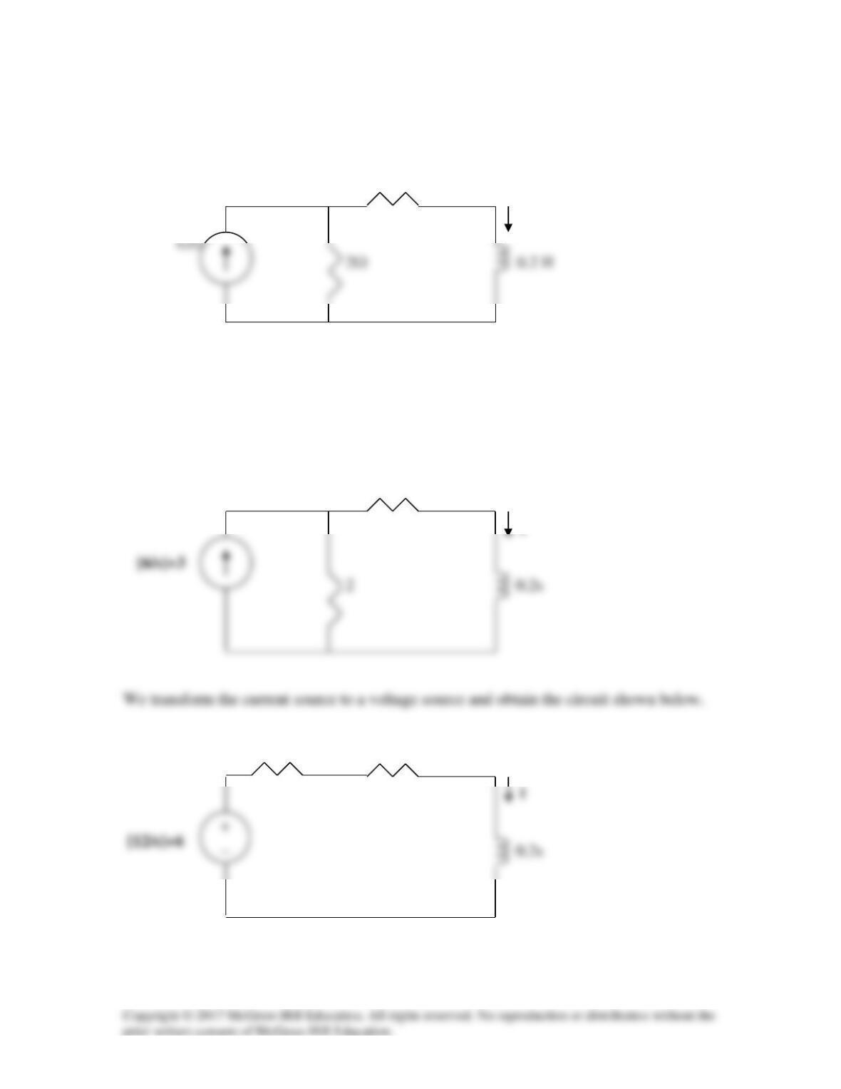
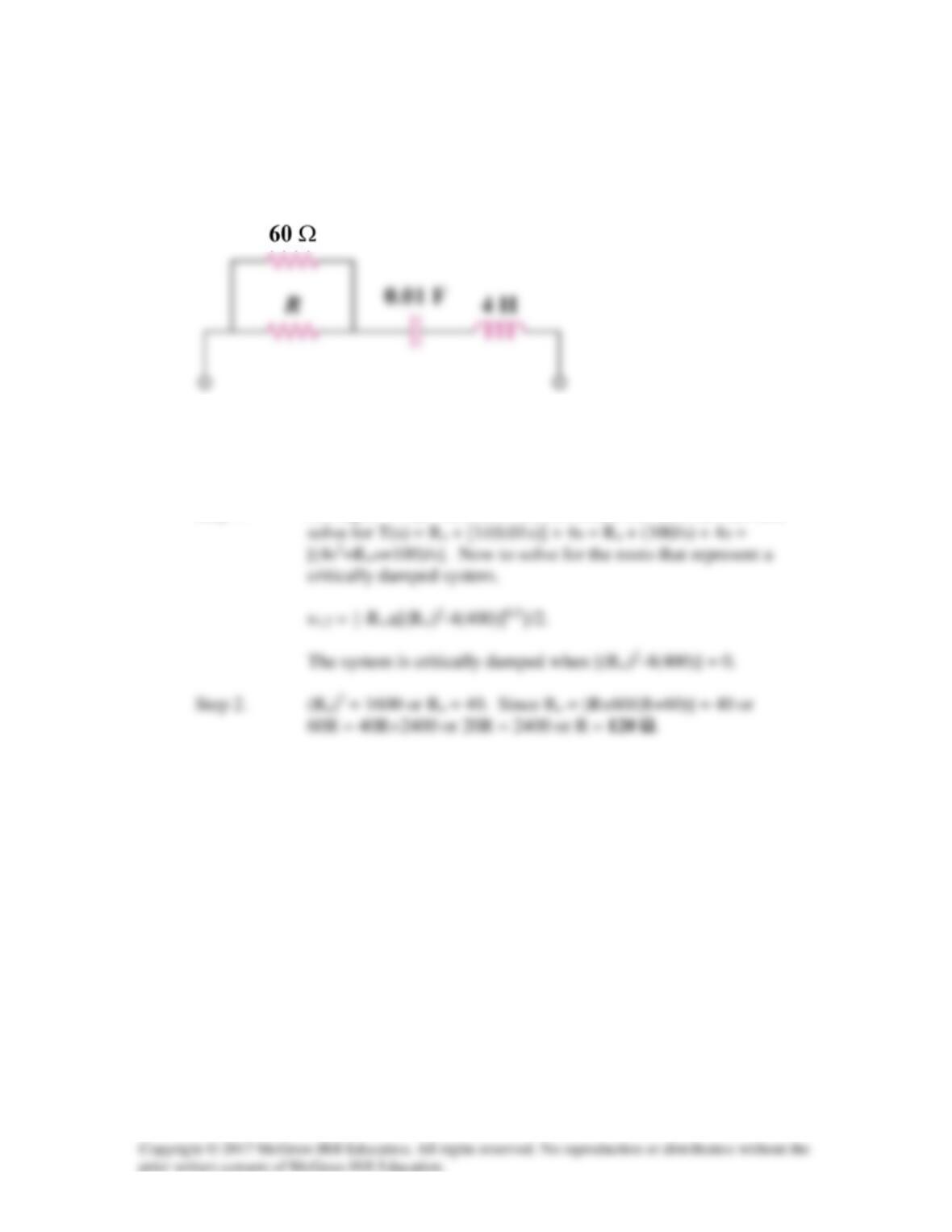
For the circuit in Fig. 16.38, calculate the value of R needed to have a critically damped
response.
Figure 16.38
For Prob. 16.15.
Solution
Step 1. Let R||60 = Ro. Next, convert the circuit into the s-domain and
Solution 16.16
The capacitor in the circuit of Fig. 16.39 is initially uncharged. Find vo(t) for t>0.
i 2 Ω 4i
Figure 16.39
For Prob. 16.16.
Solution
The circuit in the s-domain is shown below.
I 2 4I
Solution 16.17
If is(t) = 7.5e–2tu(t) A in the circuit shown in Fig. 16.40, find the value of io(t).
Figure 16.40 For Prob. 16.17.
Solution
We need to determine the initial conditions which in this case are all equal to zero
s
s
2
2s
5.7
+
I
o
2
Solution 16.18
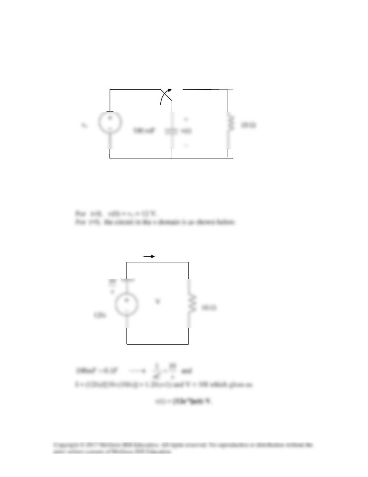
Find v(t), t>0 in the circuit of Fig. 16.41. Let vs = 12 V.
+
_
Figure 16.41
For Prob. 16.18.
Solution
+
_
I
t = 0