Solution 11.83
(a)
ooo
VIS35840)258)(60210(
1
1∠=−∠∠== ∗

Solution 11.84
(a) Maximum demand charge
000,72$30400,2 =×=
Solution 11.85
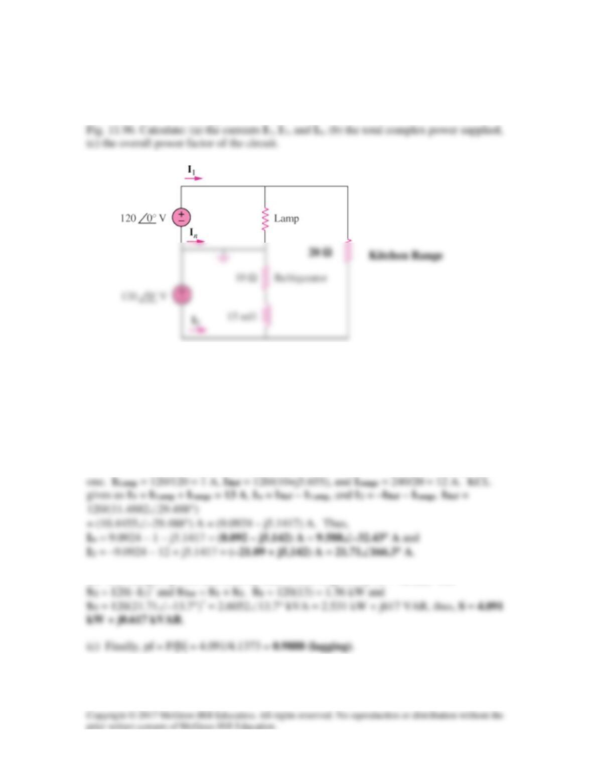
A regular household system of a single-phase three-wire allows the operation of both
120-V and 240-V, 60-Hz appliances. The household circuit is modeled as shown in
Figure 11.96
For Prob. 11.85.
Solution
(a)
655.51015602 mH 15
3
jxxxj = →
−
π
Since we know the voltage across each device we can calculate the current through each
(b) The complex power delivered by each source is given by S1 = 120(I1)* and
120 Ω
Solution 11.86
For maximum power transfer
*
LThi
*
ThLZZZZZ ==→=
Solution 11.87
jXR±=Z

Solution 11.88
(a)
°∠=°∠= 55220)552)(110(S
Solution 11.89
(a) Apparent power
== S
kVA12
2
2
*
2
)210(
V
V
Solution 11.90
Original load :
kW2000P1=
,
°=θ→=θ 79.3185.0cos 11
Additional load :
kW300P2=
,
°=θ→=θ 87.368.0cos 22
Total load :
jQP)QQ(j)PP(
212121
+=+++=+= SSS
The minimum operating pf for a 2300 kW load and not exceeding the kVA rating of the
generator is
2300
P
The maximum load kVAR for this condition is
The capacitor must supply the difference between the total load kVAR ( i.e. Q ) and the
Solution 11.91
The nameplate of an electric motor has the following information:
Line voltage: 220 V rms
Line current: 15 A rms
Solution
I = V/Z which leads to Z = [220/15]∠θ = 14.6667∠θ, S = (220)(15)∠θ = 3.3∠θ kVA,
Solution 11.92
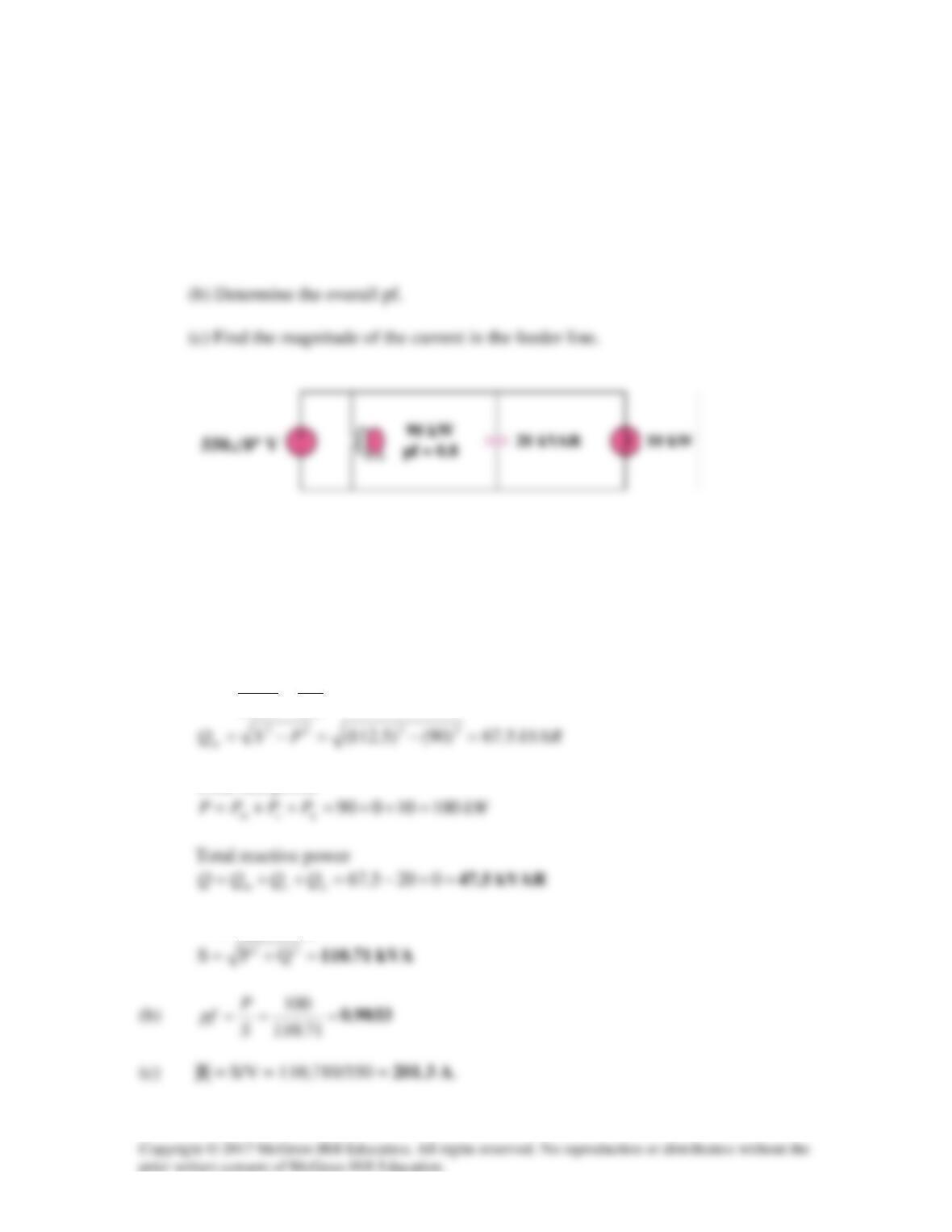
As shown in Fig. 11.97, a 550-V feeder line supplies an industrial plant consisting of a
motor drawing 90 kW at 0.8 pf (inductive), a capacitor with a rating of 20 kVAR, and
lighting drawing 10 kW.
(a) Calculate the total reactive power and apparent power absorbed by the plant.
Figure 11.97
For Prob. 11.92.
Solution
(a) Apparent power drawn by the motor is
kVA
P
S
m
5.112
8.0
90
cos ===
θ
Total real power
Total apparent power
Solution 11.93
(a)
kW7285.3)7457.0)(5(P1==
kW2.1P
2
=
,
VAR0Q2=
kVAR6.1Q4=
,
8.0sin6.0cos
44
=θ→=θ
(b)
°=
=θ 27.9
3285.7
196.1
tan
1–
Solution 11.94
°=θ→=θ 57.457.0cos 11
kVA1000MVA1S1==
For improved pf,
°=θ→=θ 19.1895.0cos
22
(a) Reactive power across the capacitor
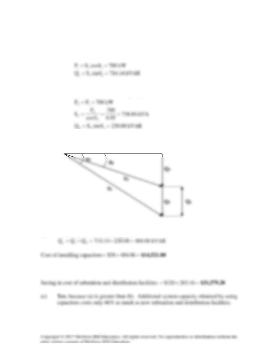
(b) Substation capacity released
21
SS −=
kVA16.26384.7361000 =−=
P1 = P2 = 700 kW
Solution 11.95
(a) Source impedance
css XjR −=Z
For maximum load transfer
LcLs
*
sL XX,RR ==→= ZZ
Solution 11.96
(a)
Hz300,V146V
Th
=
ZTh
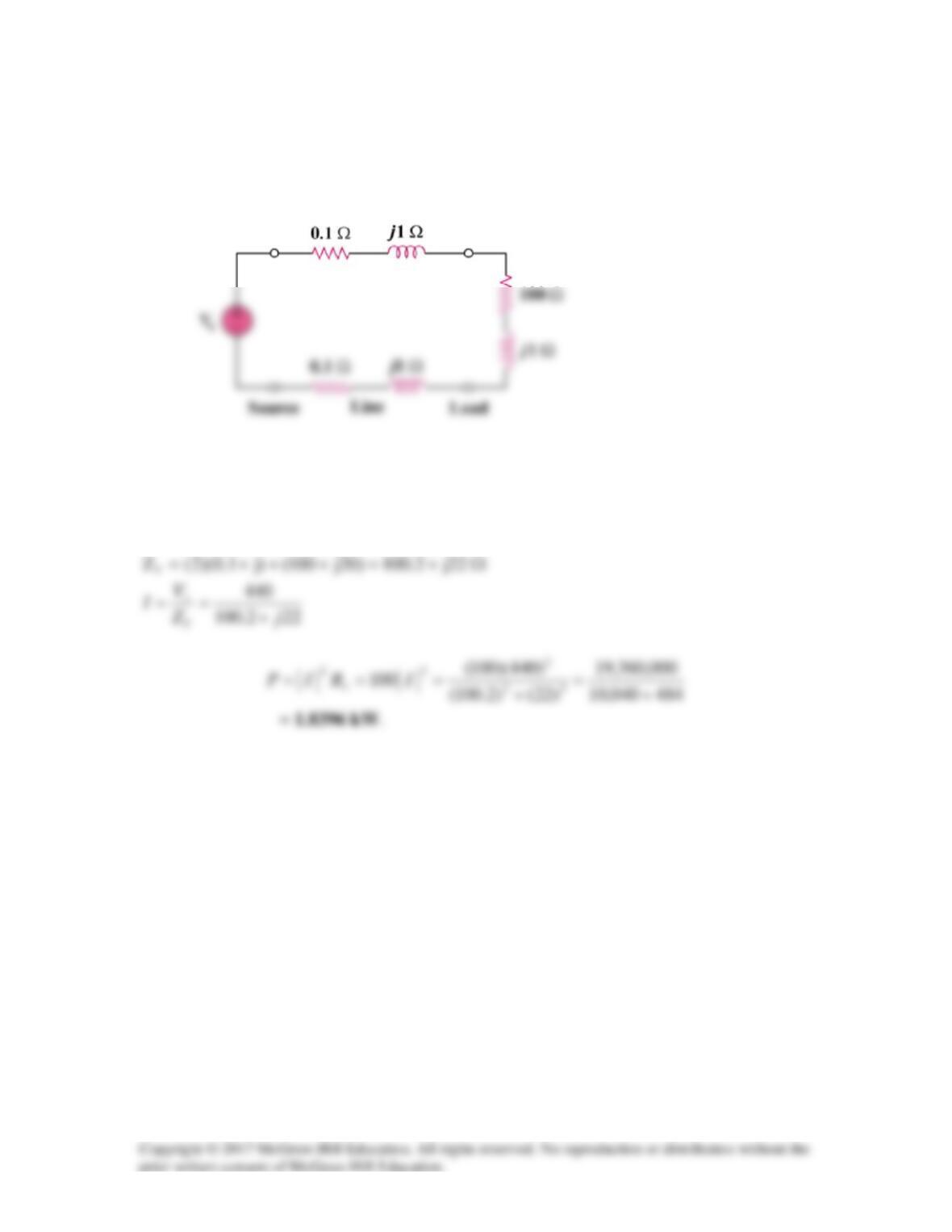
Solution 11.97
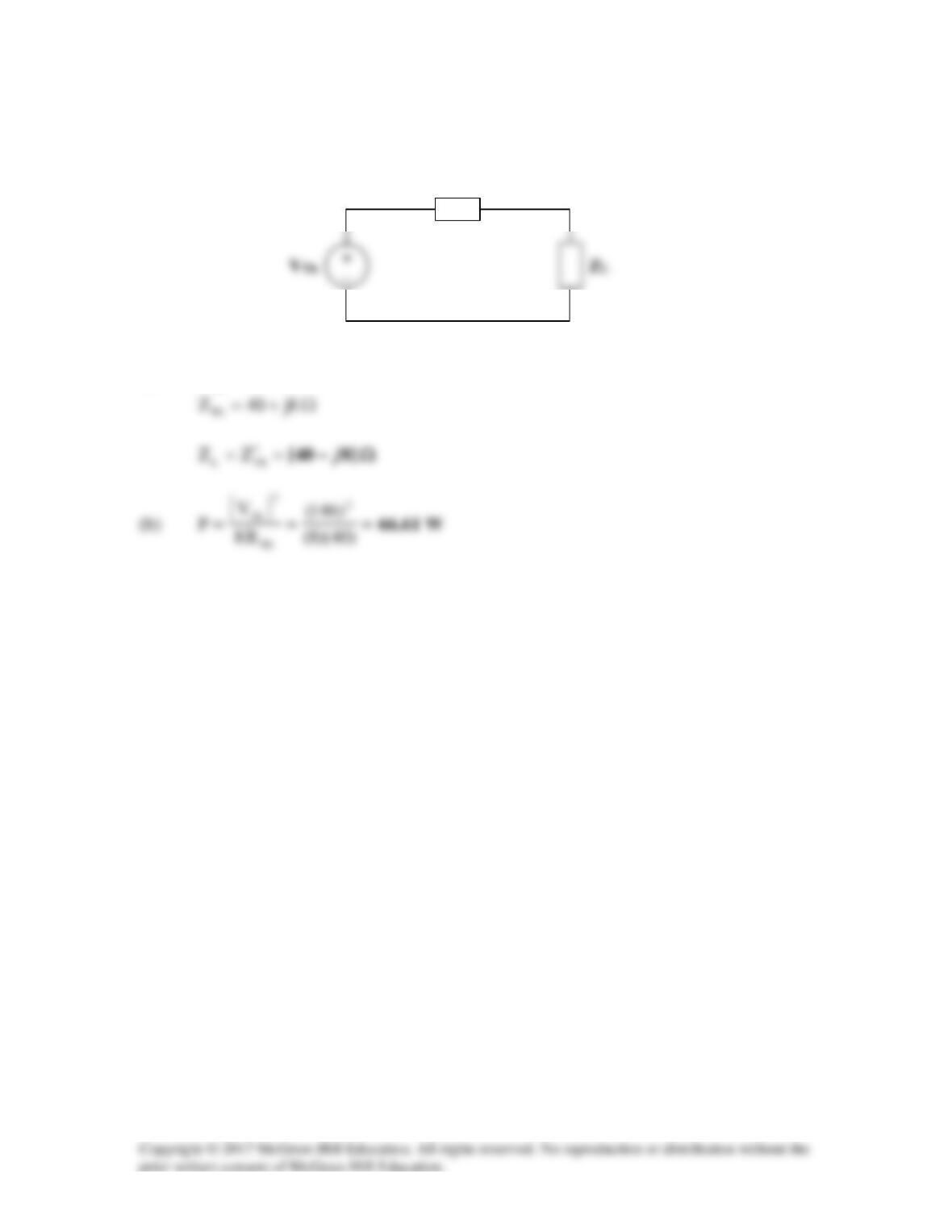
A power transmission system is modeled as shown in Fig. 11.99. If Vs = 440 ∠0° rms,
find the average power absorbed by the load.
Figure 11.99
For Problem 11.97.
Solution