Solution 7.39
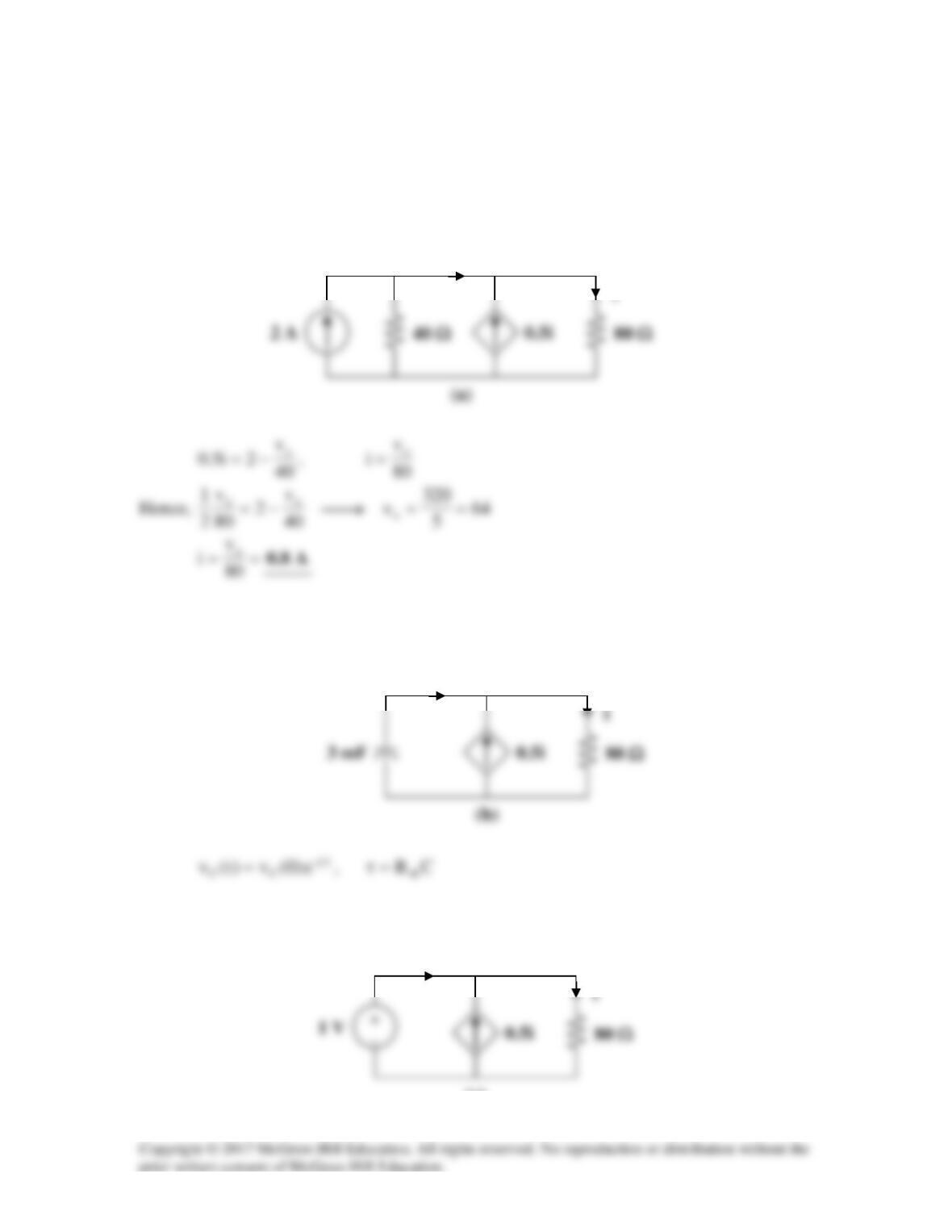
(a) Before t = 0,
[ ]
τ
∞−+∞= t–
1
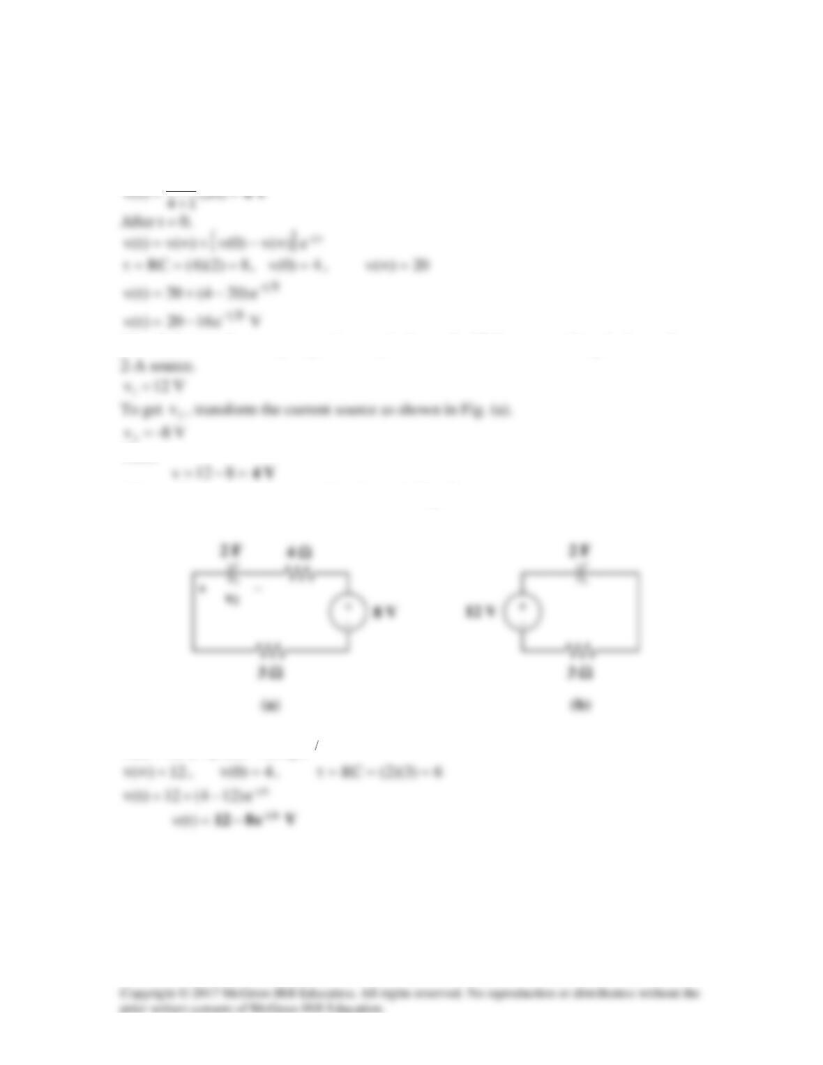
(b) Before t = 0,
21 vvv +=
, where
1
v
is due to the 12-V source and
2
v
is due to the
2
Thus,
After t = 0, the circuit becomes that shown in Fig. (b).
[ ]
τ
∞−+∞= t–
e)(v)0(v)(v)t(v
Solution 7.40
(a) Before t = 0,
=v
V12
.
(b) Before t = 0,
=v
V12
.
Solution 7.41
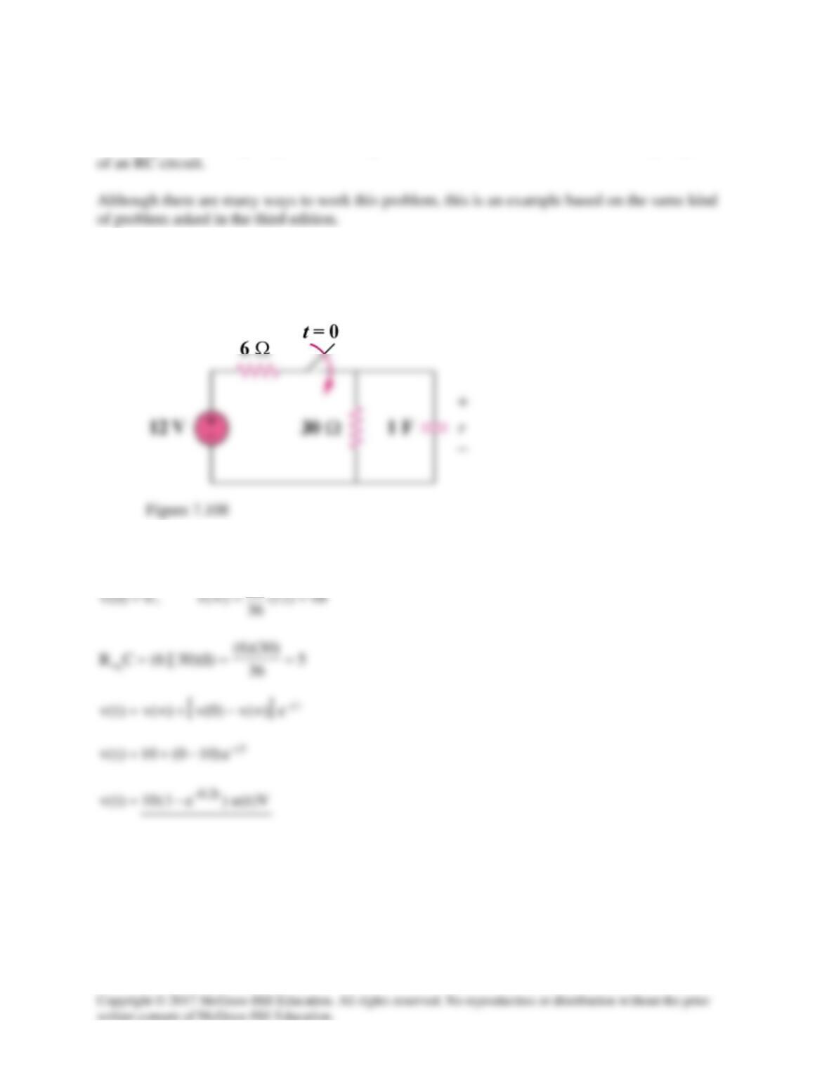
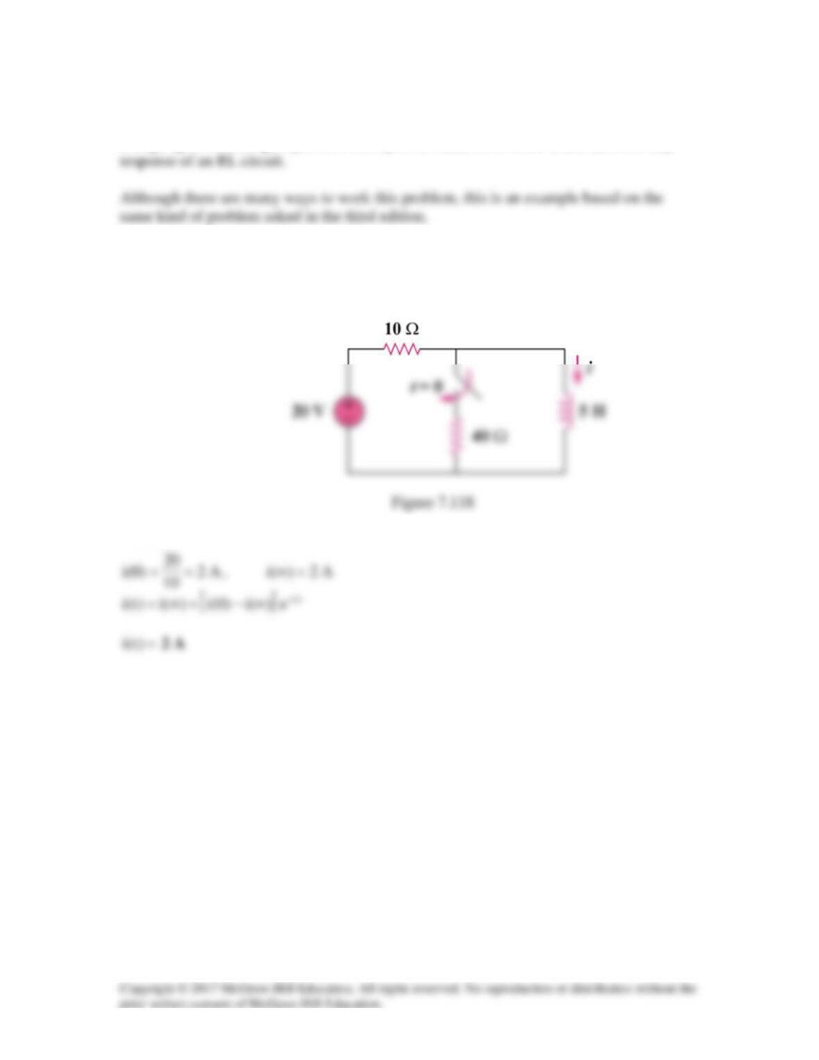
Using Fig. 7.108, design a problem to help other students to better understand the step response
Problem
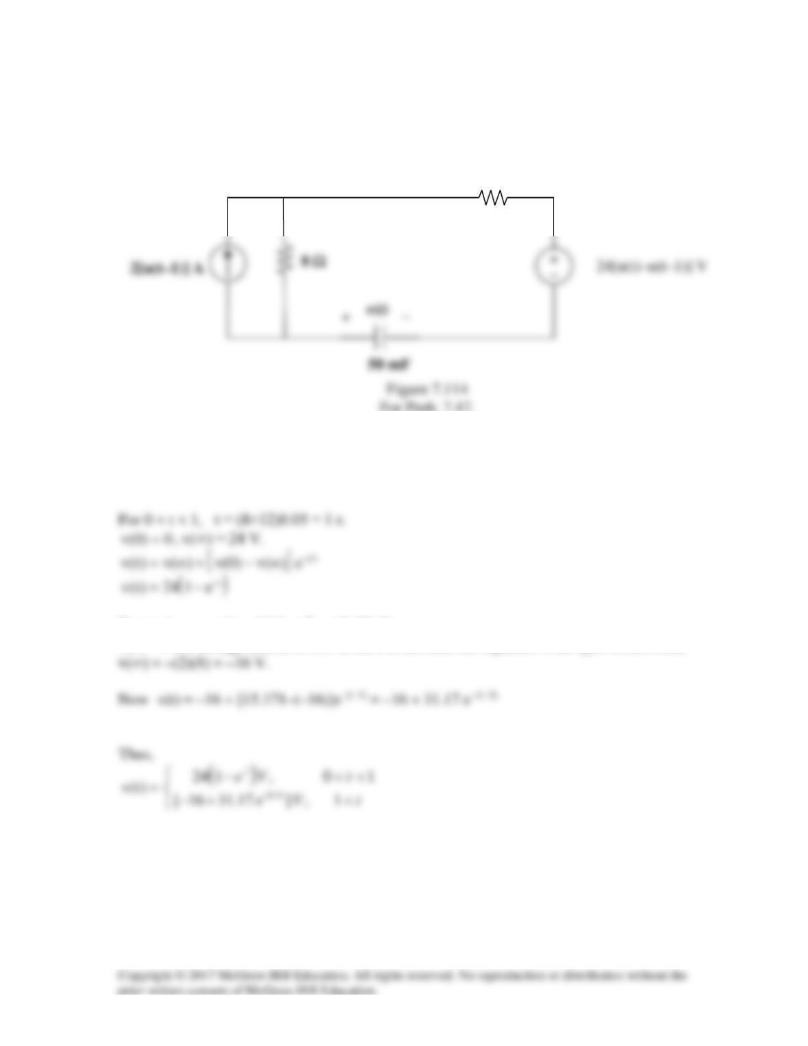
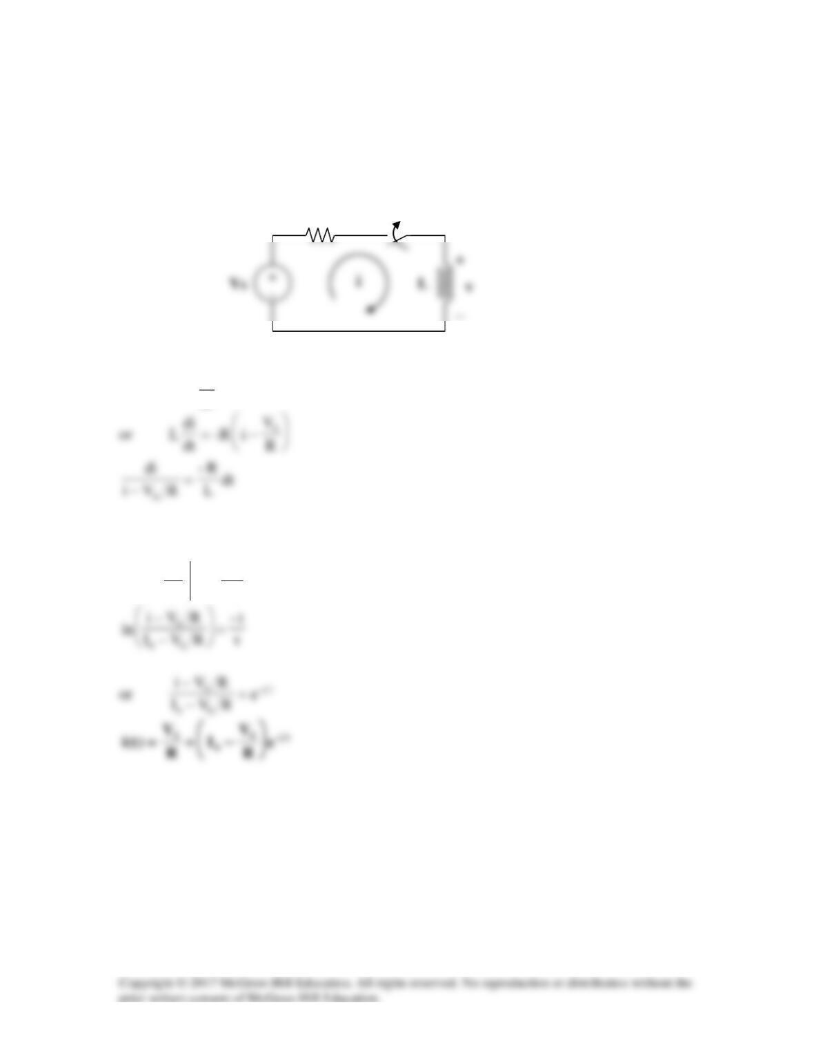
For the circuit in Fig. 7.108, find v(t) for t > 0.
Solution
30
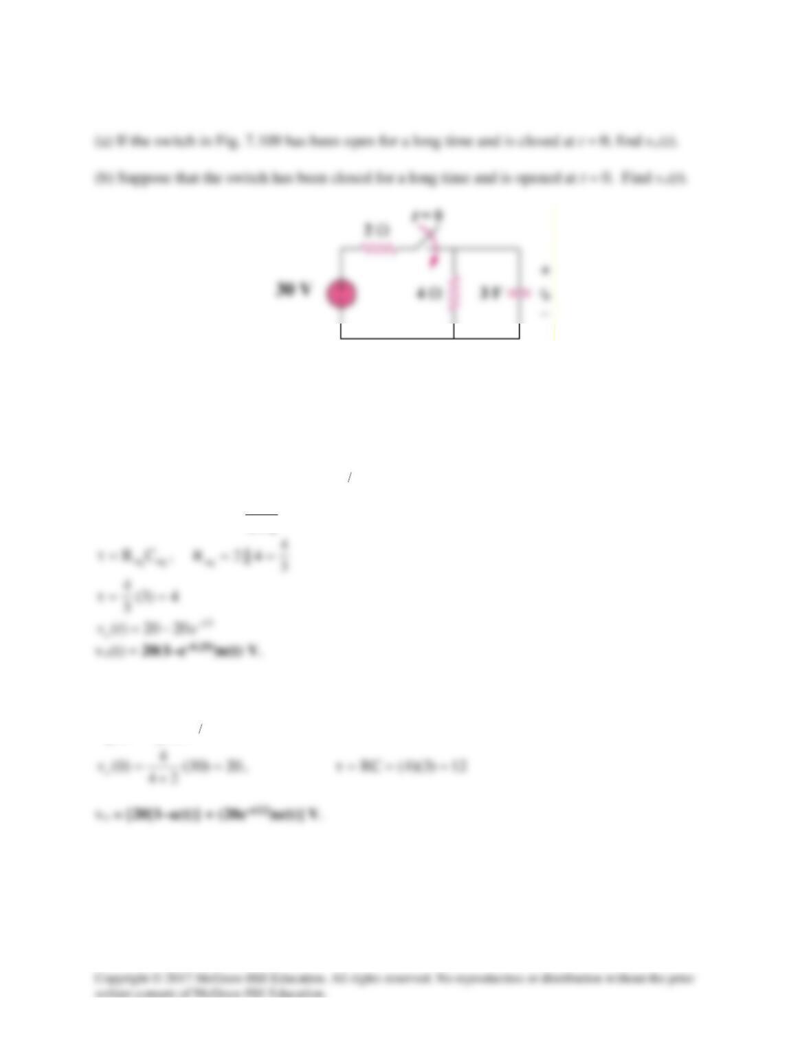
Solution 7.42
Figure 7.109
For Prob. 7.42.
Solution
(a)
[ ]
τ
∞−+∞=
t–
oooo
e)(v)0(v)(v)t(v
0)0(v
o
=
,
Vv
o
20)30(
24
4
)( =
+
=∞
(b) For this case,
0)(v
o
=∞
so that
τ
=t–
oo e)0(v)t(v
Solution 7.43
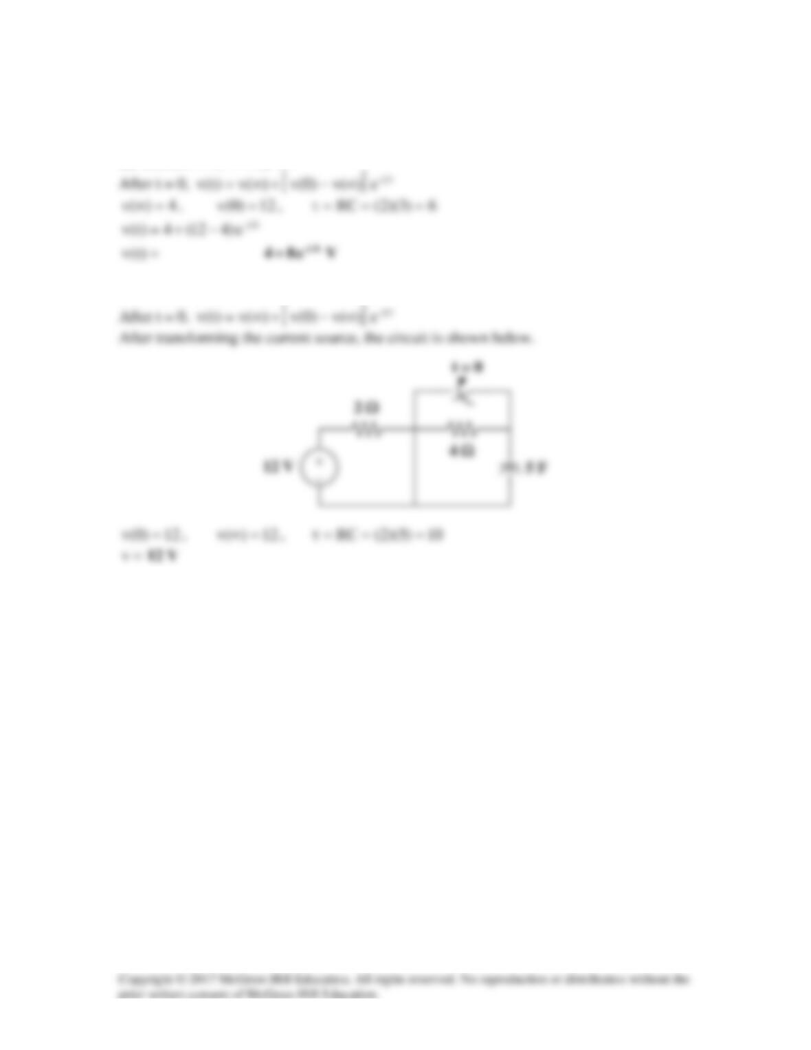
Before t = 0, the circuit has reached steady state so that the capacitor acts like an open
circuit. The circuit is equivalent to that shown in Fig. (a) after transforming the voltage
source.
After t = 0, the circuit is as shown in Fig. (b).
i
To find
th
R
, we replace the capacitor with a 1-V voltage source as shown in Fig. (c).
vC
(c)
0.5i
vC
0.5i
i
0.5i
vo
80
1
80
v
iC==
,
80
5.0
i5.0i
o
==
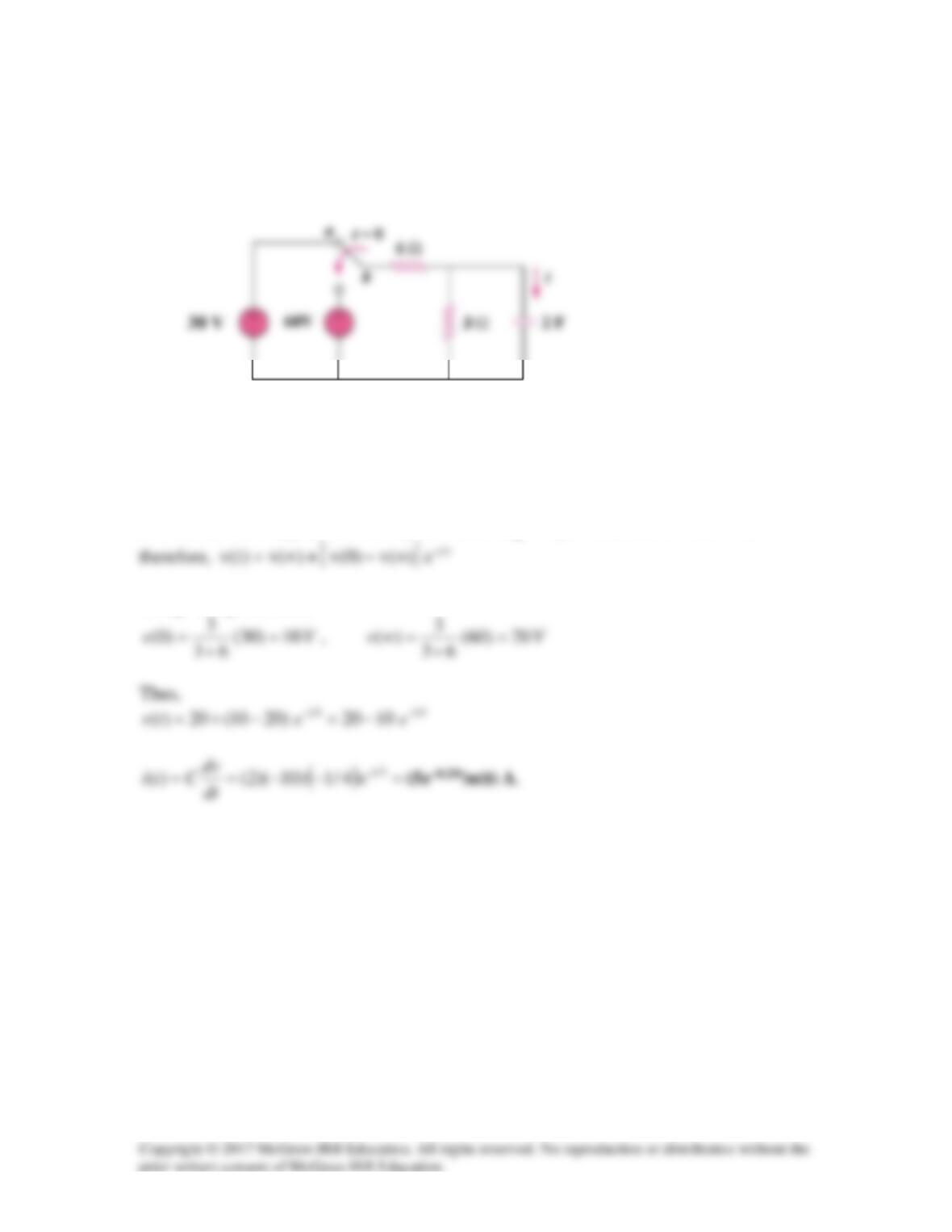
Solution 7.44
The switch in Fig. 7.111 has been in position a for a long time. At t = 0, it moves to
position b. Calculate i(t) for all t > 0.
Figure 7.111
For Prob. 7.44.
Solution
Let v(t) be the voltage across the capacitor and
Ω== 23||6R
eq
and
4RC ==τ
,
Using voltage division,
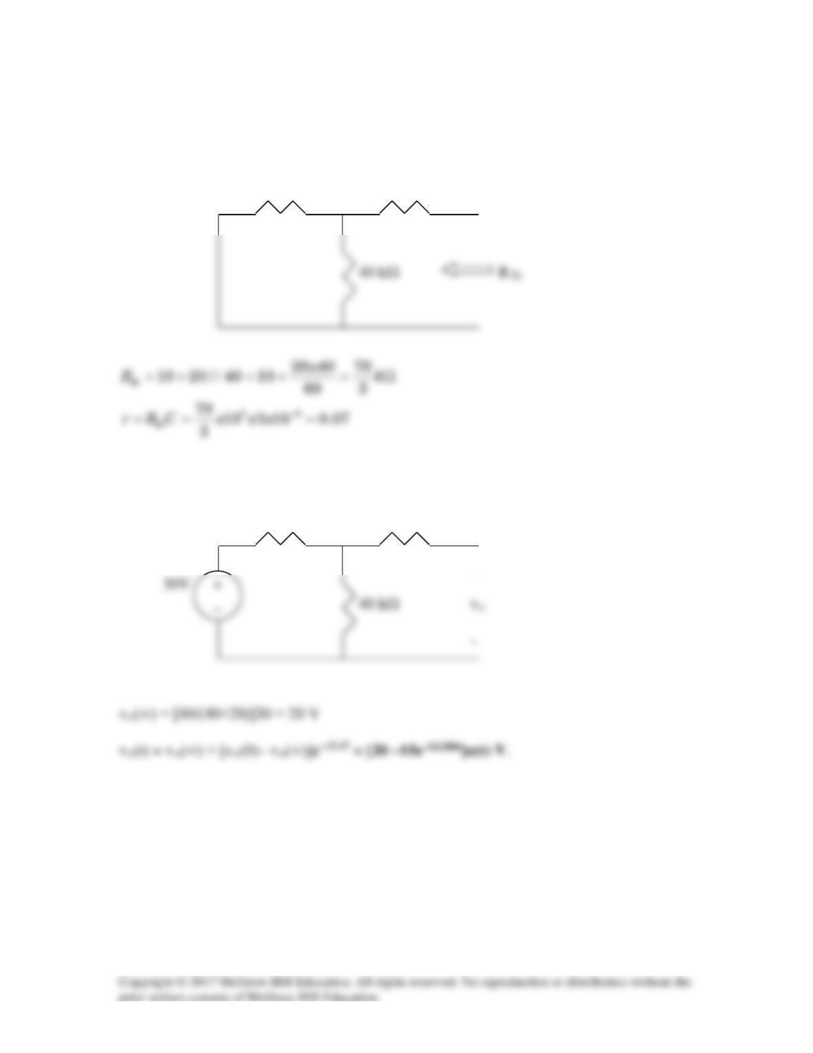
Solution 7.45
To find RTh, consider the circuit shown below.
20 kΩ 10 kΩ
To find
()
o
v∞
, consider the circuit below.
20 kΩ 10 kΩ
+

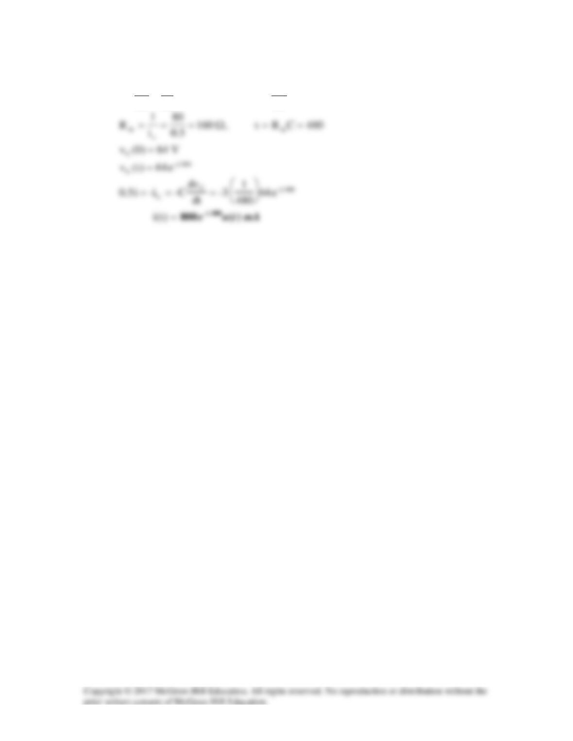
Solution 7.46
Solution 7.47
Determine v(t) for t > 0 in the circuit in Fig. 7.114 if v(0) = 0.
For Prob. 7.47.
Solution
For t < 0,
0)t(u =
,
0)1t(u =−
,
0)0(v =
For t > 1, v(1) = 24(1–e–1) = 15.171 V.
At t = ∞ the voltage source is now a short circuit and the capacitor is an open circuit thus,
12 Ω
Solution 7.48
For t < 0,
1-t)(u =
,
For t > 0,
0-t)(u =
,
0)(v =∞
Solution 7.49
For 0 < t < 1,
0)0(v =
,
8)4)(2()(v ==∞
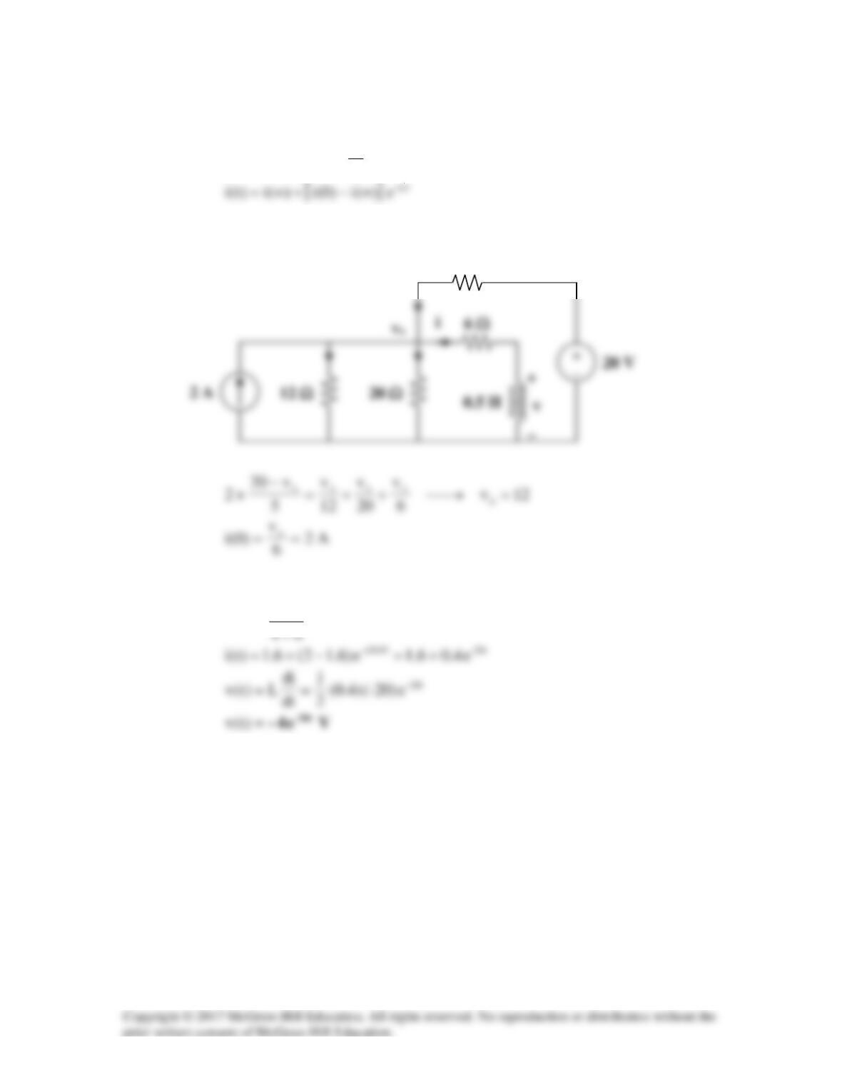
Solution 7.50
For the capacitor voltage,
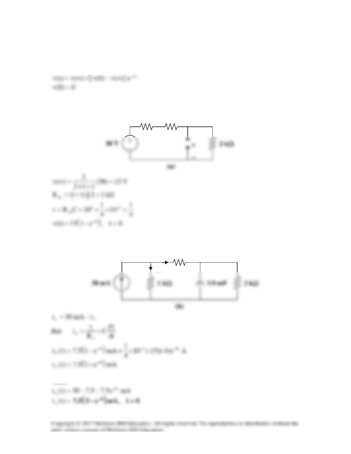
For t > 0, we transform the current source to a voltage source as shown in Fig. (a).
We now obtain
x
i
from v(t). Consider Fig. (b).
1 kΩ
v
ix
iT
1 kΩ
1 kΩ
+
Solution 7.51
Consider the circuit below.
After the switch is closed, applying KVL gives
dt
di
LRiVS+=
Integrating both sides,
t
L
R–
R
V
iln )t(i
I
S
0
=
−
which is the same as Eq. (7.60).
R
t = 0
Solution 7.52
Using Fig. 7.118, design a problem to help other students to better understand the step
Problem
For the circuit in Fig. 7.118, find i(t) for t > 0.
Solution
Solution 7.53
(a) Before t = 0,
=
+
=23
25
i
A5
(b) Before t = 0, the inductor acts as a short circuit so that the 2 Ω and 4 Ω
resistors are short–circuited.
A6
Solution 7.54
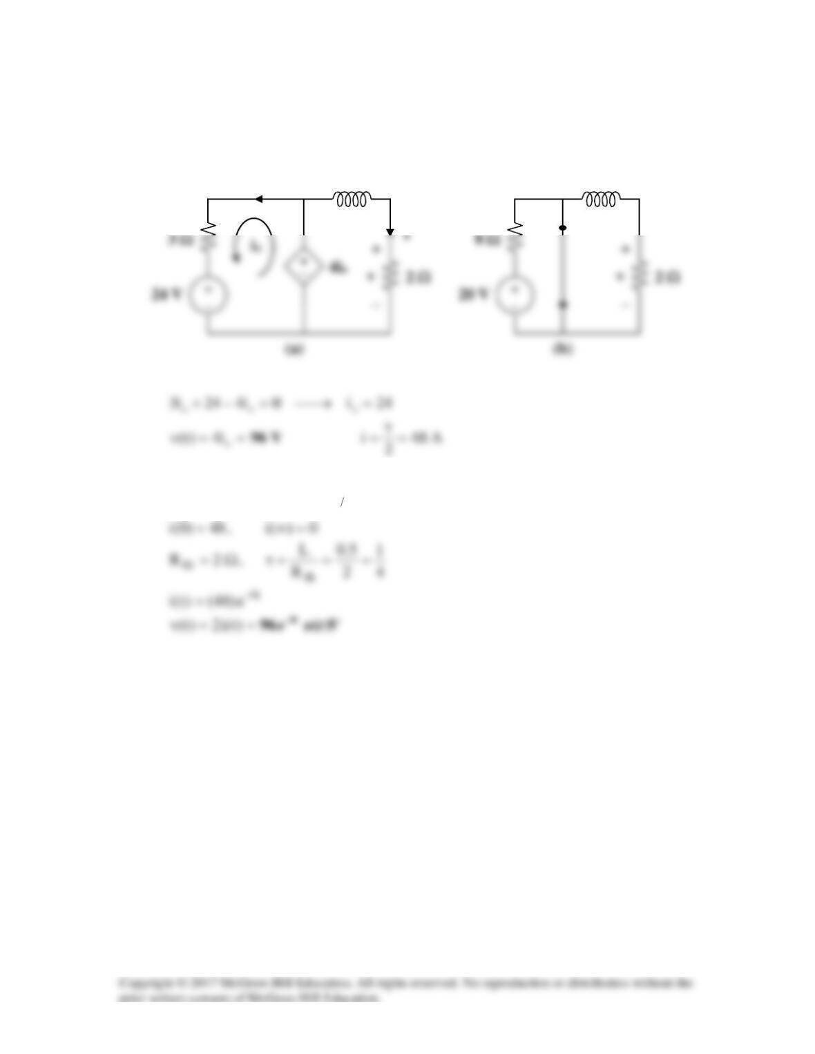
(a) Before t = 0, i is obtained by current division or
+
After t = 0,
(b) Before t = 0,
=
+
=32
10
)t(i
A2
To find
)(i ∞
, consider the circuit below, at t = when the inductor becomes a short
circuit,
v
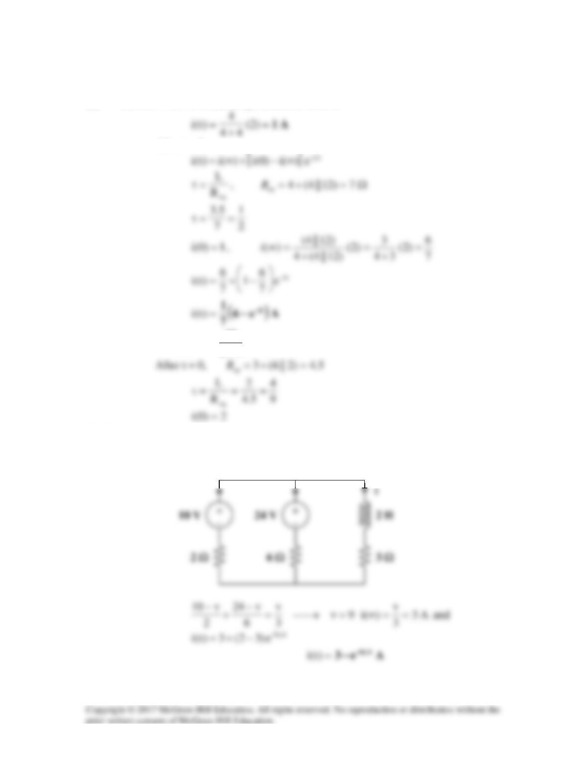
Solution 7.55
For t < 0, consider the circuit shown in Fig. (a).
For t > 0, consider the circuit in Fig. (b).
[ ]
τ
∞−+∞= t–
e)(i)0(i)(i)t(i
0.5 H
io
0.5 H
Solution 7.56
Ω=+= 105||206R eq
,
05.0
R
L==τ
i(0) is found by applying nodal analysis to the following circuit.
6 Ω
Since
45||20 =
,
6.1)4(
4
)(i =
=∞
5 Ω
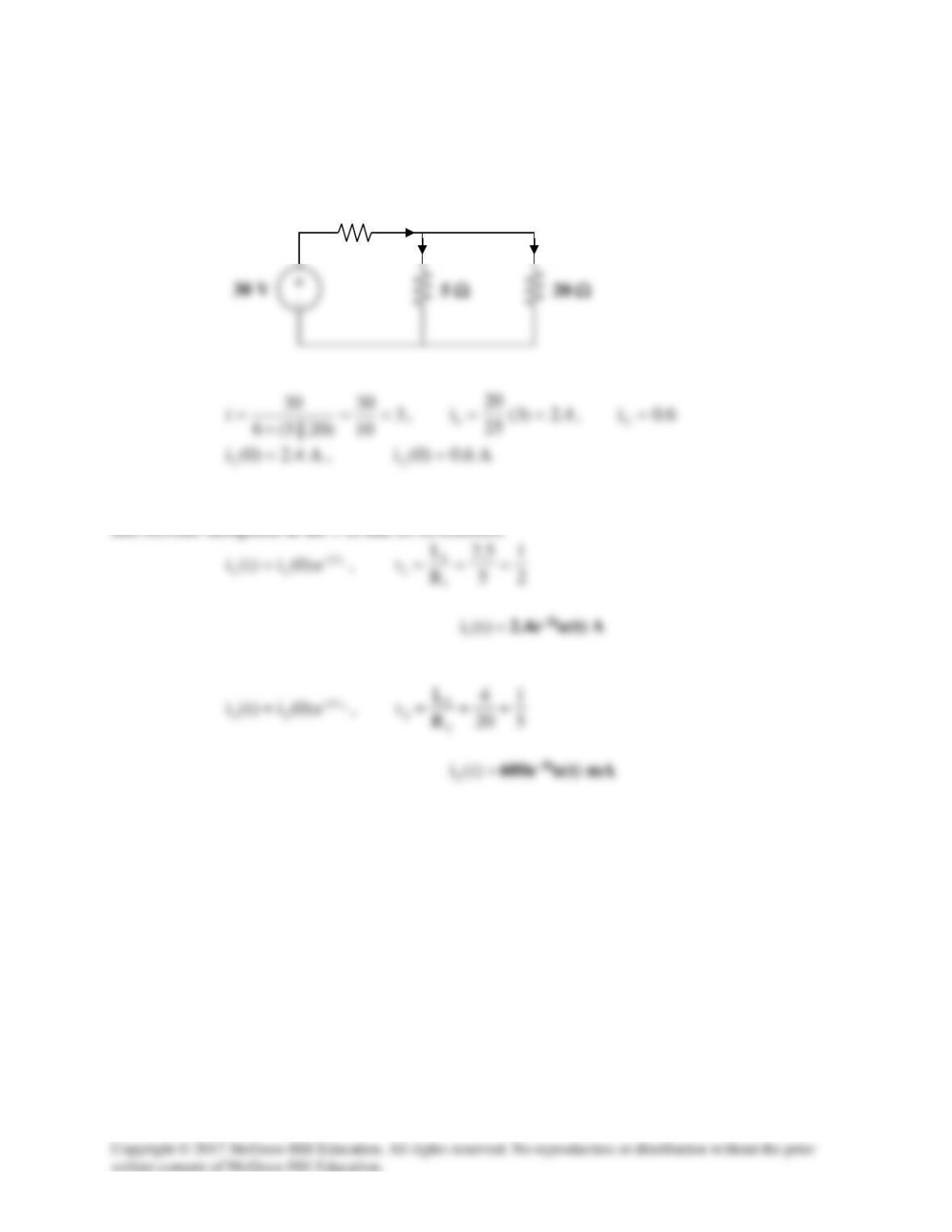
Solution 7.57
At
−
=0t
, the circuit has reached steady state so that the inductors act like short circuits.
For t > 0, the switch is closed so that the energies in
1
L
and
2
L
flow through the closed switch
6 Ω
i
1
i
i
2