Solution 16.34
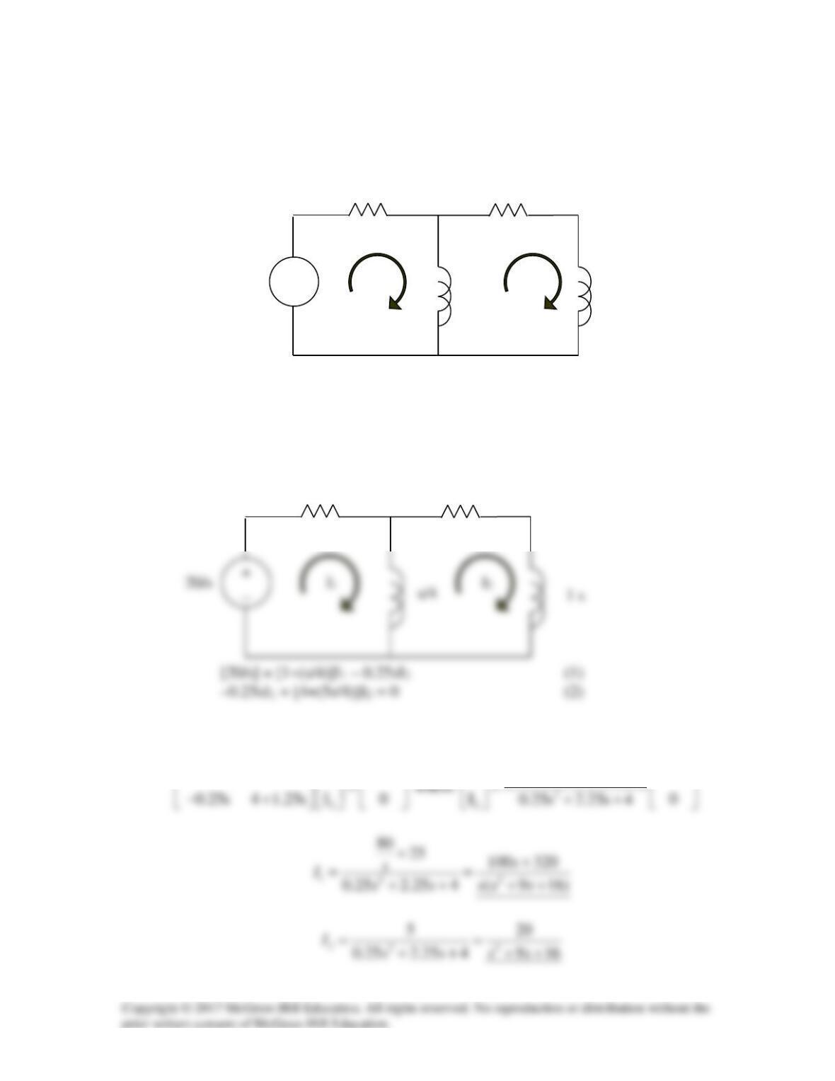
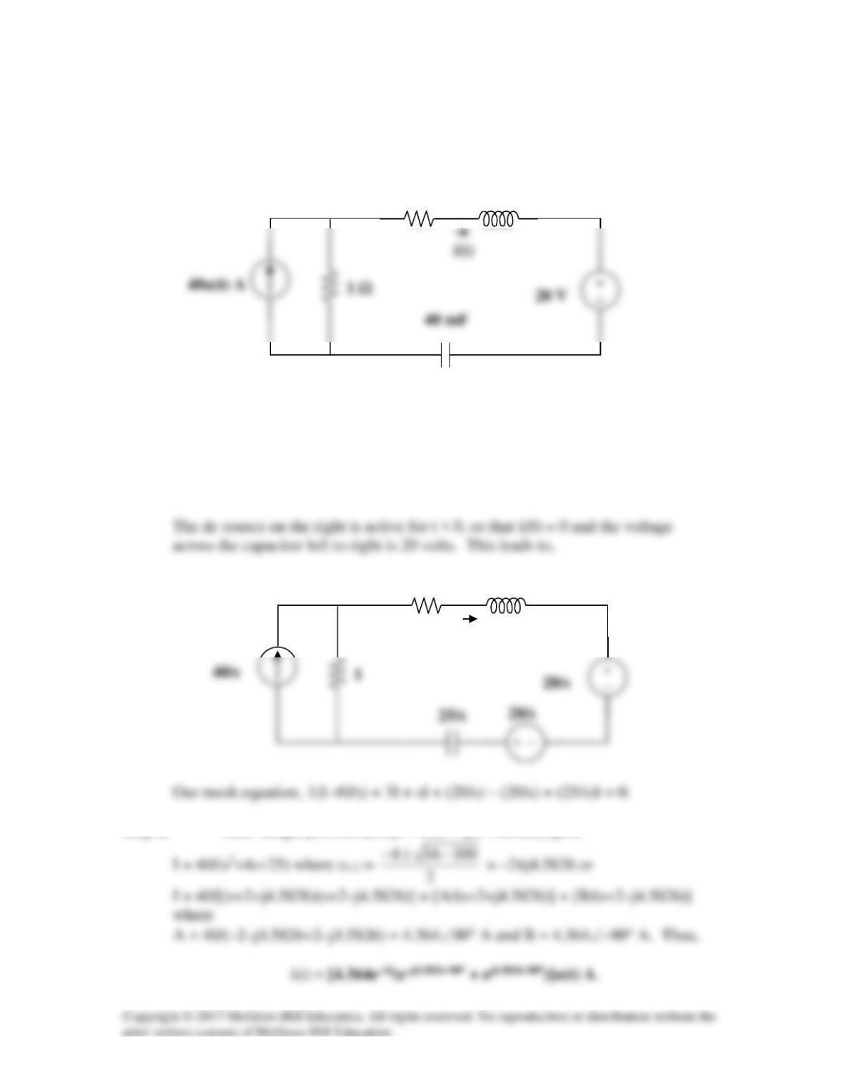
Solve for the mesh currents in the circuit of Fig. 16.57. You may leave your results in the
s-domain.
Figure 16.57 For Prob. 16.34.
Solution
In the s-domain, the circuit is as shown below.
In matrix form,
1
I
1 0.25s 0.25s 20 / s
+−
1
4 1.25s 0.25s
I20 / s
0.25s 1 0.25s
+
+
1 Ω
4
1 Ω
4 Ω
+
_
20u(t) V
I
1
I
2
(1/4)H
1 H
s
Vo
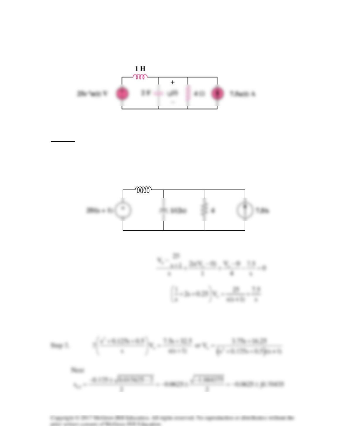
Solution 16.35
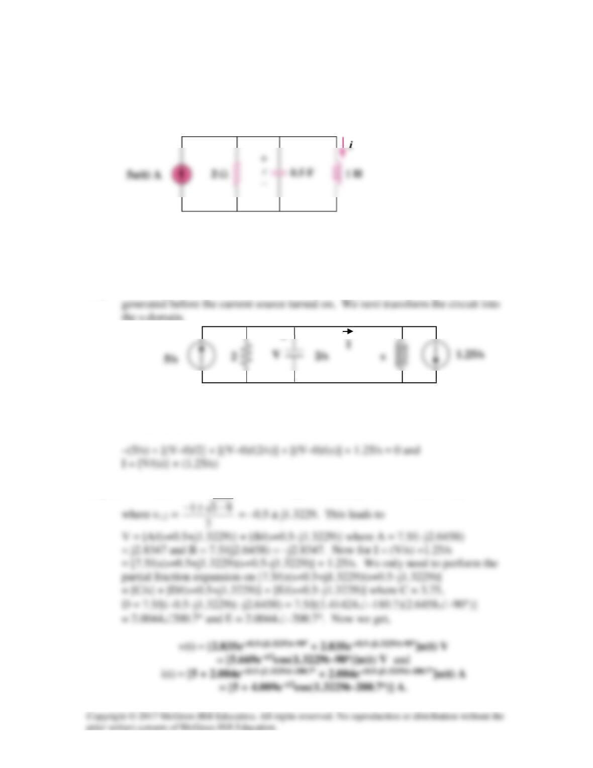
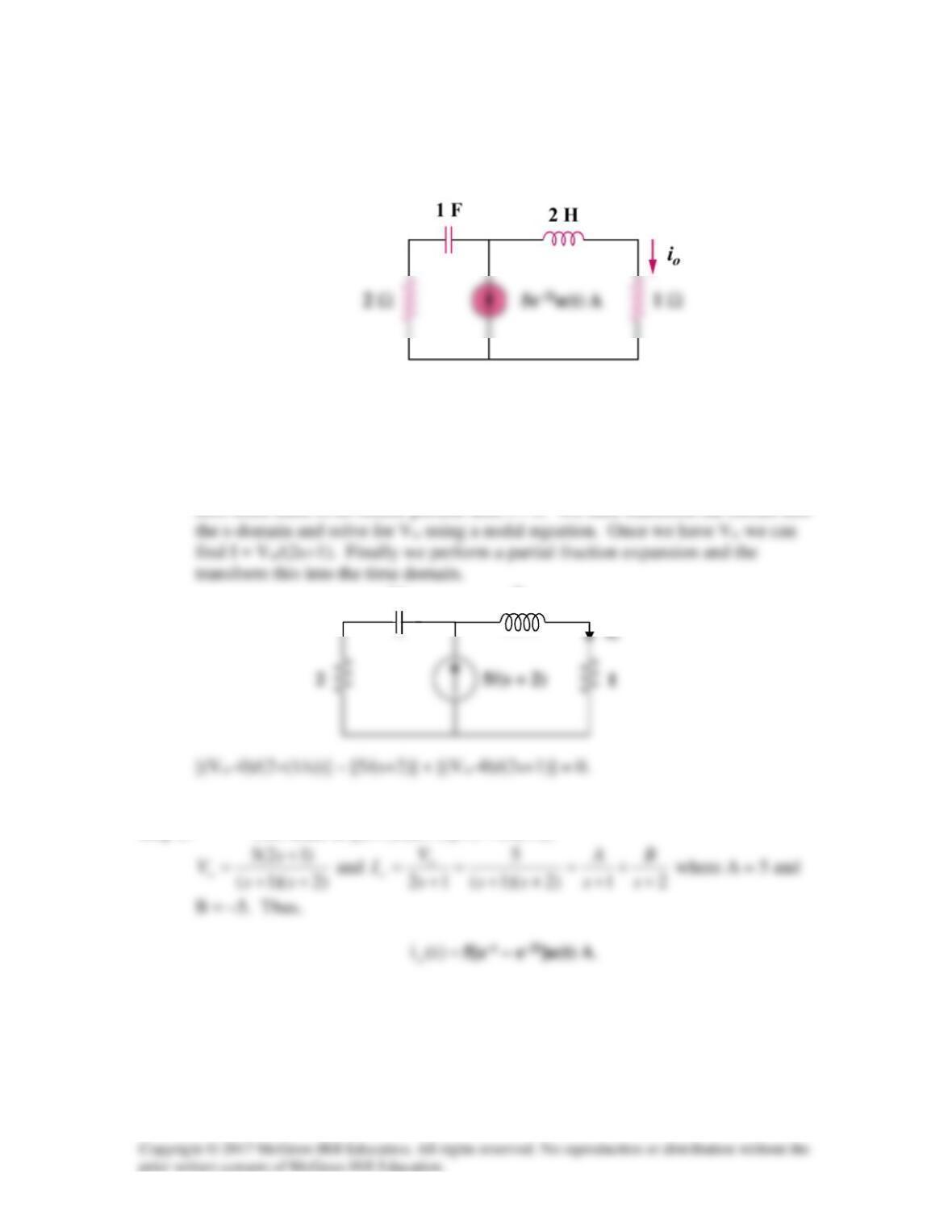
Find vo(t) in the circuit in Fig. 16.58.
Figure 16.58
For Prob. 16.35.
Solution
Step 1. First we note that the initial condition on the capacitor and inductor must
be equal to zero since the circuit is unexcited until t = 0. Next we transform the
circuit into the s-domain.
We then can solve for Vo using nodal analysis.
Finally we solve for Vo, perform a partial fraction expansion and then convert
into the time–domain.
( )( )( )
o
3.75s 16.25
Vs 1 s 0.0625 j0.70435 s 0.0625 j0.70435
+
=+++ +−
Thus,
vo(t) =
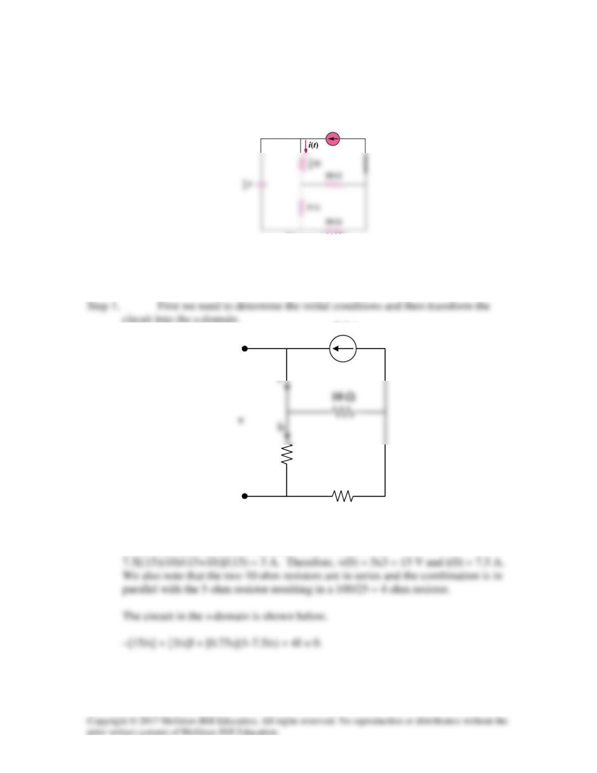
Solution 16.36
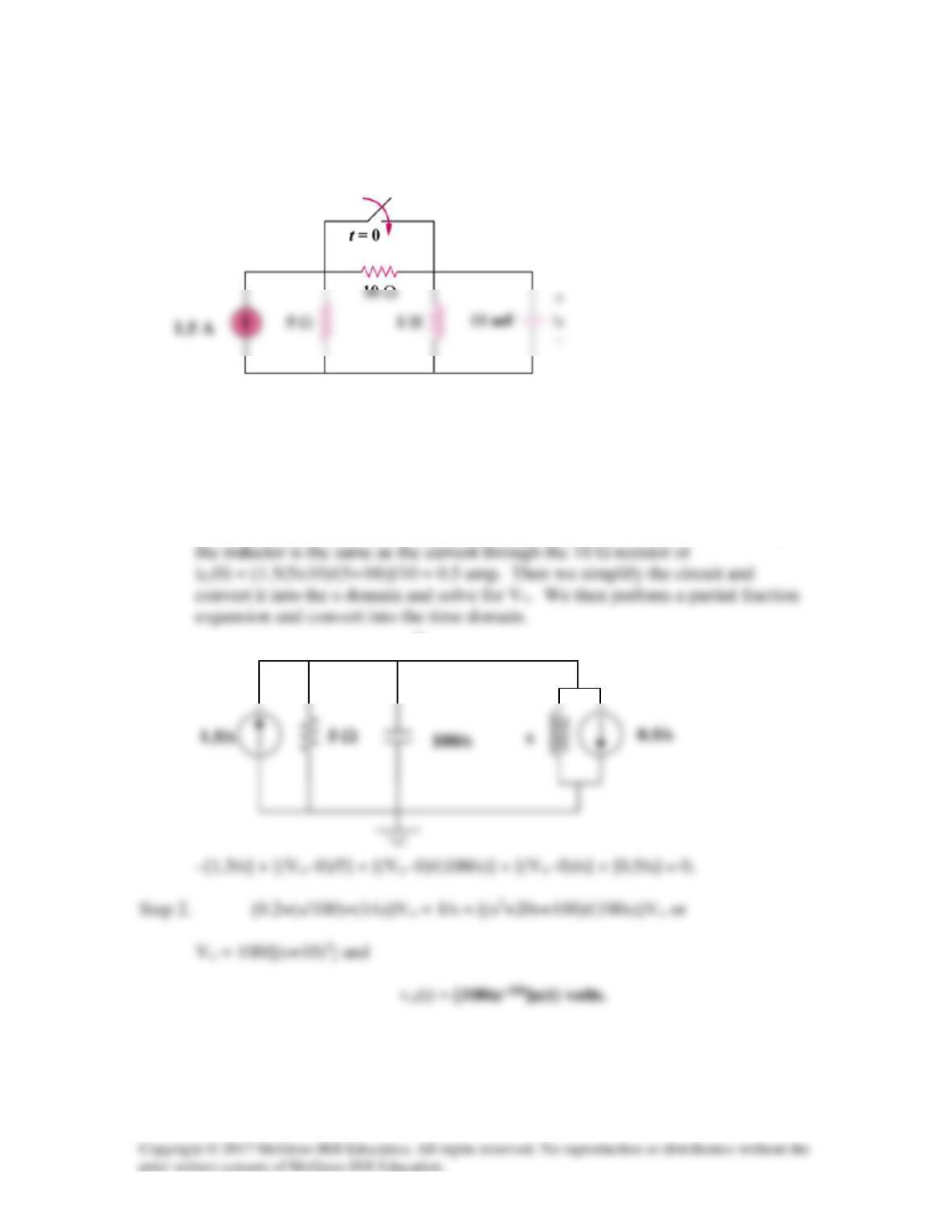
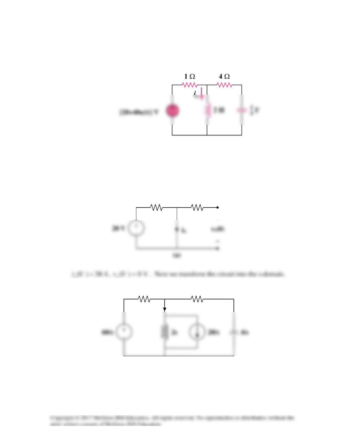
Refer to the circuit in Fig. 16.59. Calculate i(t) for t > 0.
Figure 16.59
For Prob. 16.36.
Solution
i
Clearly i = 7.5 A. The current then travels through the parallel combination of the
10 ohm resistor and the combined 15 ohm resistance. i1 =
7.5(1–u(t)) A
10 Ω
+
−
5 Ω
7.5 A
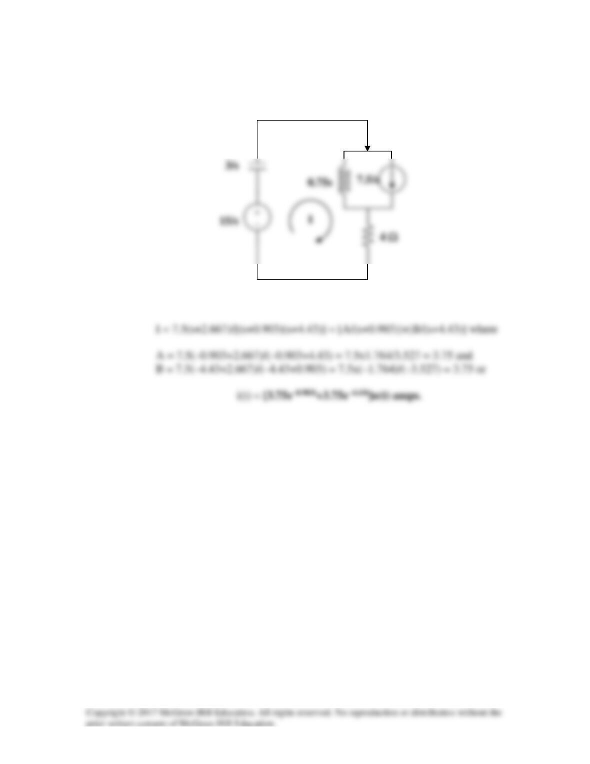
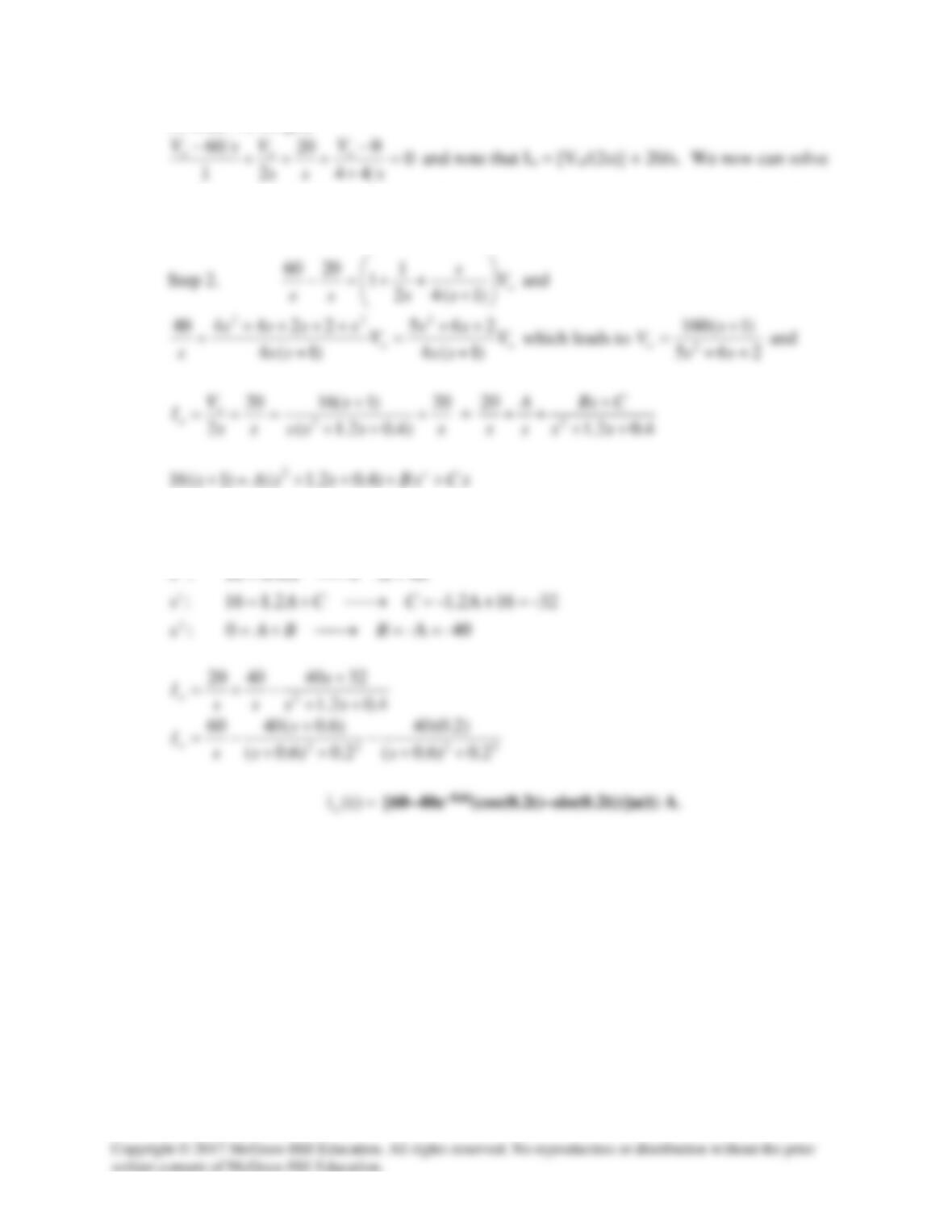
Step 2. [(s2+5.333s+4)/(4s/3)]I = 5.625+15/s = 5.625(s+2.667)/s or
I
Solution 16.37
Determine v for t > 0 in the circuit in Fig. 16.60.
Figure 16.60
For Prob. 16.37.
Solution
Step 1. First we establish the initial conditions and then transform the circuit into
the s– domain. Now we write a mesh equation and solve for I. We note that
250 mH
3 Ω
0.25s
3
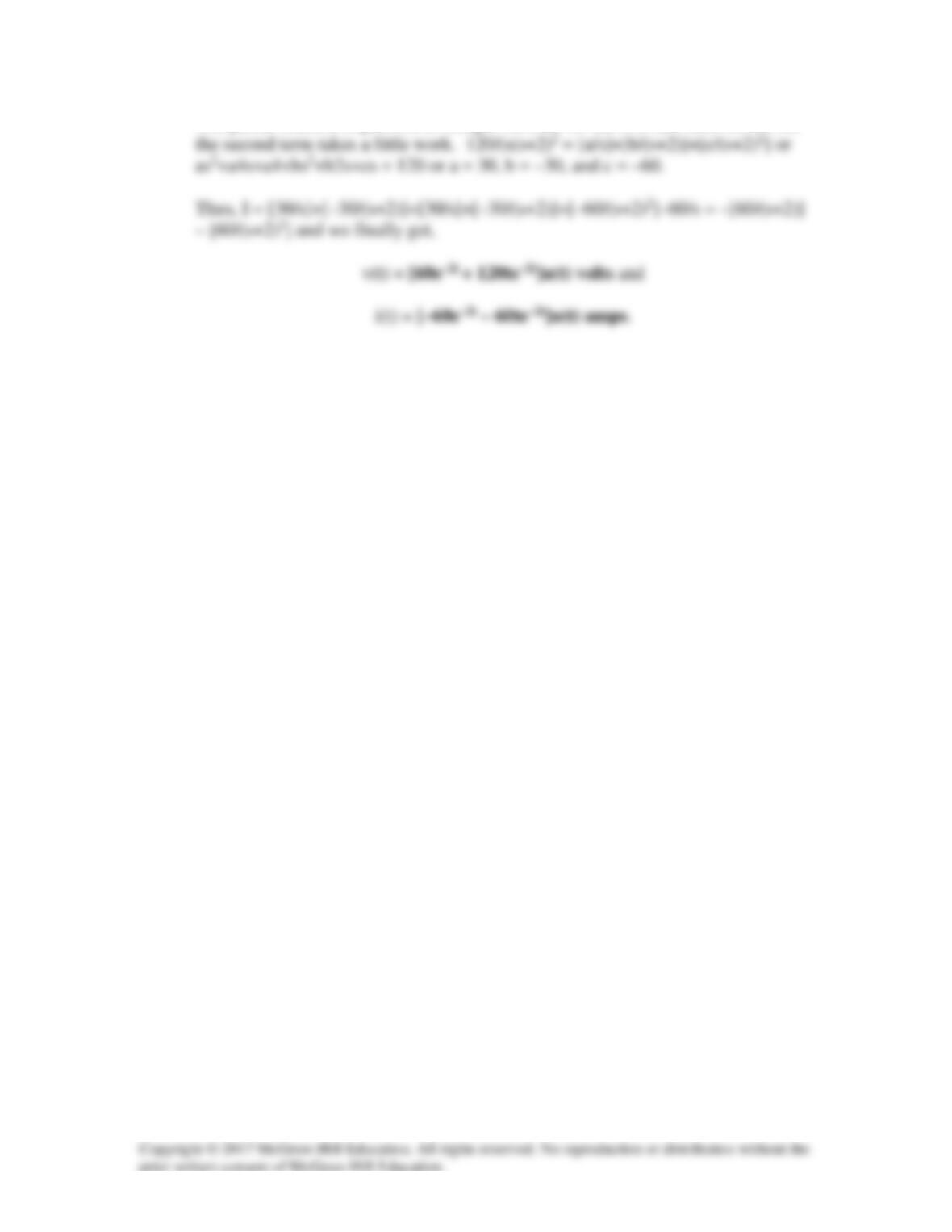
Step 2. [4+3+0.25s+5+(2/s)]I = 60/s = [(0.25s2+12s+2)/s]I or
Solution 16.38
The switch in the circuit of Fig. 16.61 is moved from position a to b (a make before break
switch) at t = 0. Determine i(t) for t > 0.
Figure 16.61 For Prob. 16.38.
Solution
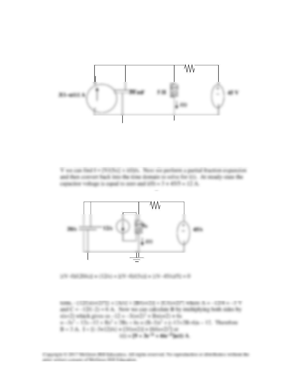
Step 1. We first determine the initial conditions. We assume that vC(0) = 0 since
Step 2. [2s+(50/s)+20]I = 7.5+15/s = [(s2+10s+25)/(0.5s)]I = 7.5(s+2)/s or
+ −
6 Ω
3.75/s
+ −
20 Ω
3.75/s
Solution 16.39
For the network in Fig. 16.62, find i(t) for t > 0.
1 Ω
Figure 16.62 For Prob. 16.39.
Solution
Step 1. First we need to determine the initial conditions and then transform the
circuit into the s-domain. Then we solve for I, preform a partial fraction
expansion a d then convert the answer back into the time domain.
20/s
Step 2. Now we get [1+3+s+25/s]I = 40/s = [(s2+4s+25)/s]I or
1 H
3 Ω
I
s
3
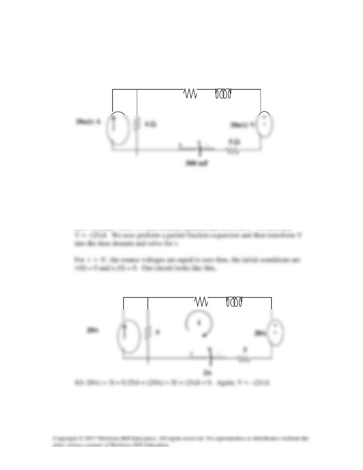
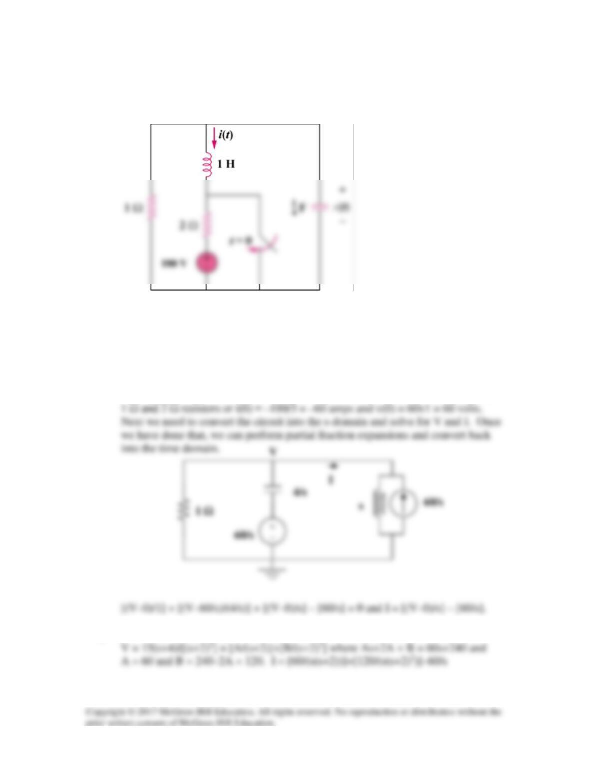
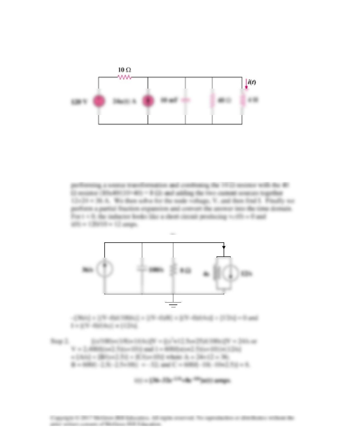
Solution 16.40
In the circuit of Fig. 16.63, find v(t) and i(t) for t > 0. Assume v(0) = 0 V and
i(0) = 1.25 A.
Figure 16.63 For Prob. 16.40.
Solution
Step 1. First we note that the initial conditions are given so that they were
Now all we need to do is to write a nodal equation and solve for V and I. Once
we have them, we perform partial fraction expansions and convert them back into
the time domain.
Step 2. [0.5+0.5s+(1/s)]V = 3.75/s = [(s2+s+2)/(2s)]V or V = 7.5/(s2+s+2)
+
−
Vo
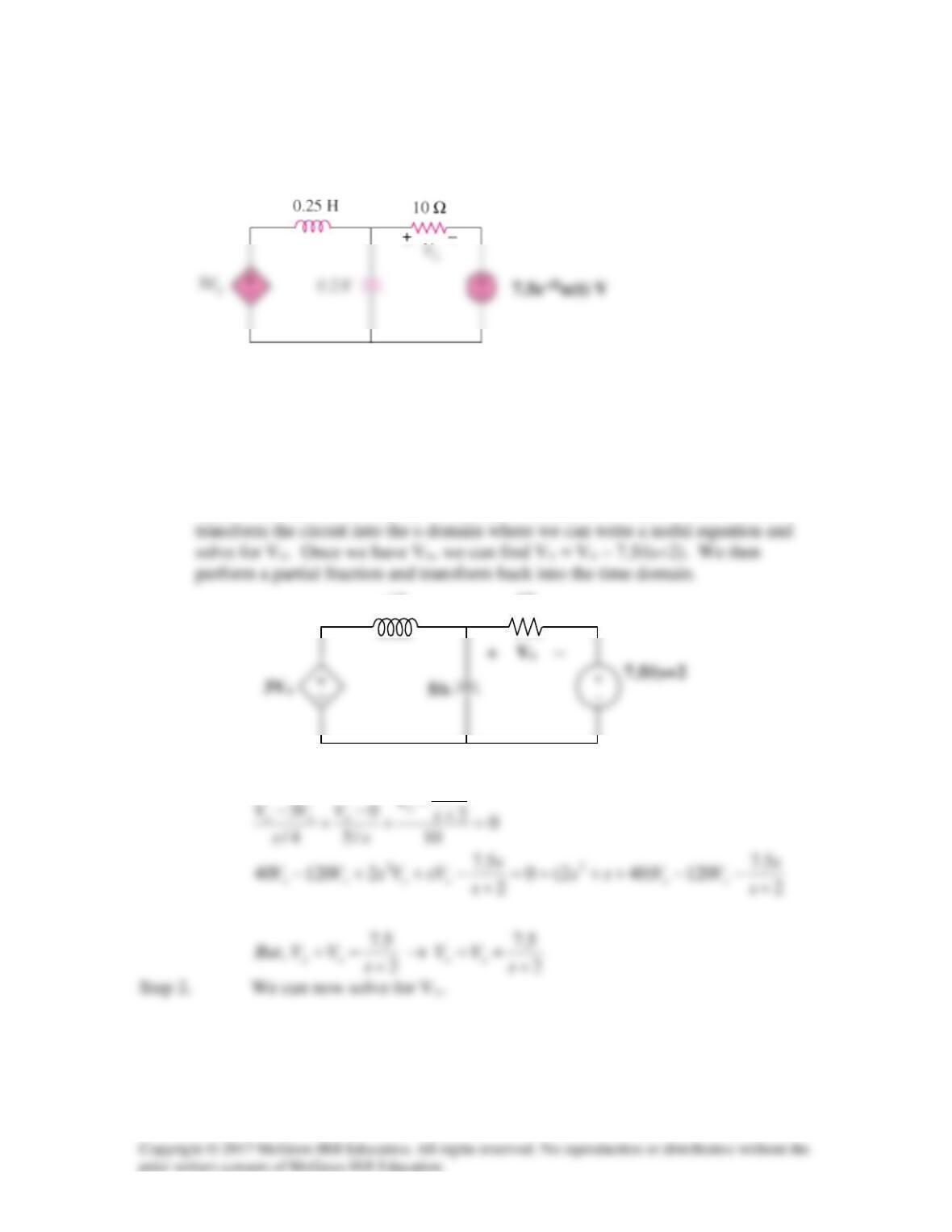
Solution 16.41
Find the output voltage vo(t) in the circuit of Fig. 16.64.
Figure 16.64
For Prob. 16.41.
Solution
Step 1. First we need to determine the initial conditions. We see that vo(0) = 0
since the inductor becomes a short. We also note that the initial current through
Solution 16.42
Given the circuit in Fig. 16.65, find i(t) and v(t) for t > 0.
Figure 16.65
For Prob. 16.42.
Solution
Step 1. First we need to find the initial conditions. Since the inductor becomes a
short and the capacitor becomes an open circuit, all the current flows through the
Step 2. [(1+(s/4)+(1/s)]V = [(s2+4s+4)/(4s)]V = 15+60/s = 15(s+4)/s or
The partial fraction expansion is straight forward for the first and third terms, but
5
V
Solution 16.43
Determine i(t) for t > 0 in the circuit of Fig. 16.66.
Figure 16.66 For Prob. 16.43.
Solution
Step 1. First we determine the initial conditions and then transform the circuit into
the s-domain. We can then write a node equation and solve for V. Once we have
Step 2. Now we get [(s/20)+(1/(5s))+1/5]V = [(s2+4s+4)/(20s)]V = –3/s or
V = –60/[(s+2)2]. Finally we get I = –{12/[s(s+2)2]} + 12/s or just for the first
5
Ω
I
V
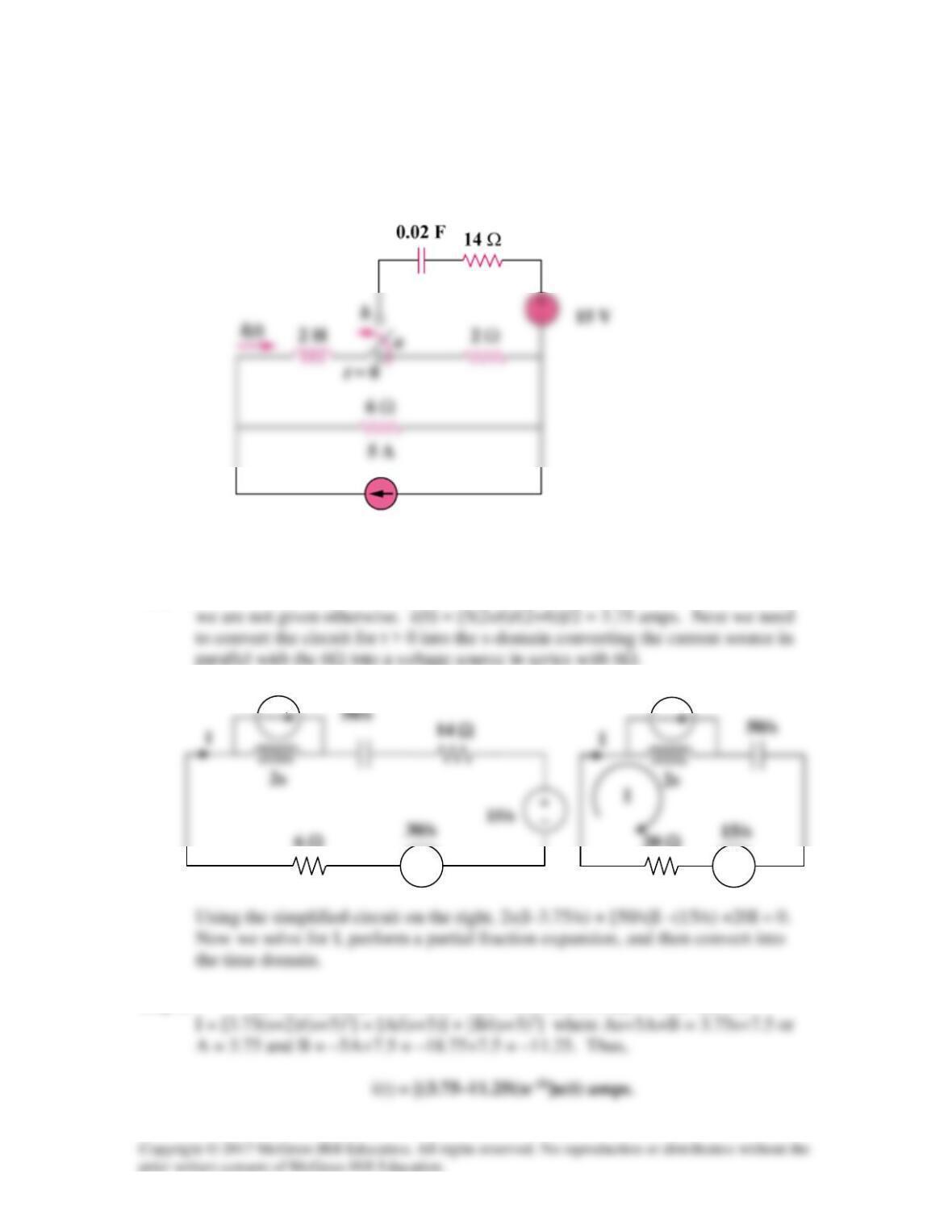
Solution 16.44
For the circuit in Fig. 16.67, find i(t) for t > 0.
Figure 16.67
For Prob. 16.44.
Solution
Step 1. First we identify the initial conditions. Then we simplify the circuit (for
t > 0) and then transform it into the s-domain. We simplify the circuit by
Solution 16.45
Find v(t) for t > 0 in the circuit in Fig. 16.68.
Figure 16.68
For Prob. 16.45.
Solution
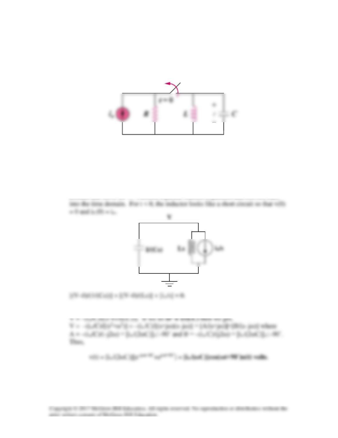
Step 1. First, determine the initial conditions. Next convert the circuit into the s–
domain and solve for V. Perform a partial fraction expansion and convert back
Step 2. [Cs+(1/(Ls))]V = [C{s2+(1/(LC))}/s]V = –io/s or
Solution 16.46
Determine io(t) in the circuit in Fig. 16.69.
Figure 16.69
For Prob. 16.46.
Solution
Step 1. First we determine the initial conditions which in this case are equal to
Step 2. This leads to [(s+1)/(2s+1)]Vo = 5/(s+2)
2s
1/s
Vo
Solution 16.47
Determine io(t) in the network shown in Fig. 16.70.
Figure 16.70
For Prob. 16.47.
Solution
Step 1. We first find the initial conditions from the circuit in Fig. (a),
4 Ω
1 Ω
+
4
1
Vo
Io
(b)
At node Vo we get,
for Vo and then for Io. We then perform a partial fraction expansion and transform back
into the time domain.
Equating coefficients :
0
Solution 16.48
Find vx(s) in the circuit shown in Fig. 16.71.
Figure 16.71
For Prob. 16.48.
Solution
Step 1. First we need to determine the initial conditions which in this case are
equal to zero since there are no independent sources active until t = 0. Next we
5.7
10
s/4
Vo