Solution 13.60
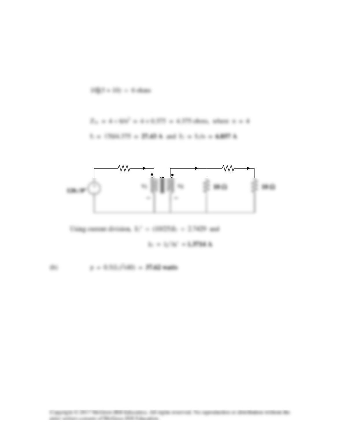
(a) Transferring the 40-ohm load to the middle circuit,
ZL’ = 40/(n’)2 = 10 ohms where n’ = 2
We transfer this to the primary side.
I2
4 Ω
1 : 4
+
+
I1
5 Ω
I2’
Solution 13.61
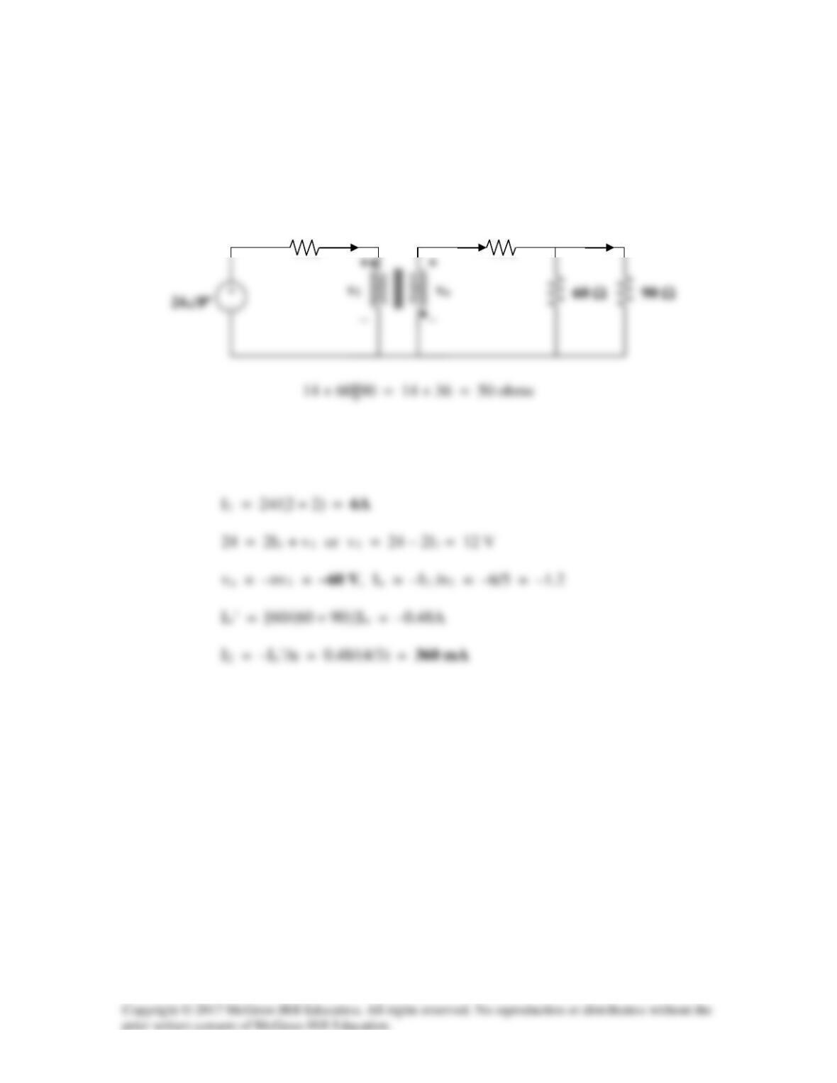
We reflect the 160–ohm load to the middle circuit.
ZR = ZL/n2 = 160/(4/3)2 = 90 ohms, where n = 4/3
We reflect this to the primary side.
ZR’ = ZL’/(n’)2 = 50/52 = 2 ohms when n’ = 5
Io
2 Ω
1 : 5
I1
14 Ω
Io’

Solution 13.62
(a) Reflect the load to the middle circuit.
We now reflect this to the primary circuit so that
(b) I2 = –I1/n, n = 2.5
Solution 13.63
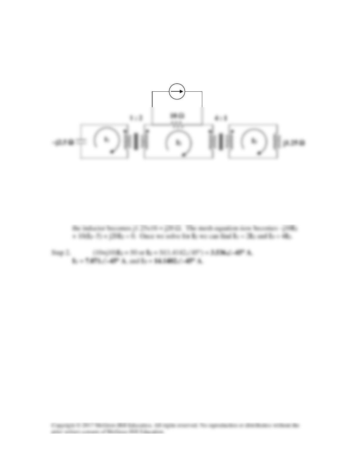
Find the mesh currents in the circuit of Fig. 13.128 below.
Figure 13.127
For Prob. 13.63.
Solution
Step 1. We can start by reflecting the –j2.5 Ω and the j1.25 Ω impedances into the
center circuit and then solve for I2. The capacitor becomes –j2.5×4 = –j10 Ω and
5 A
Solution 13.64
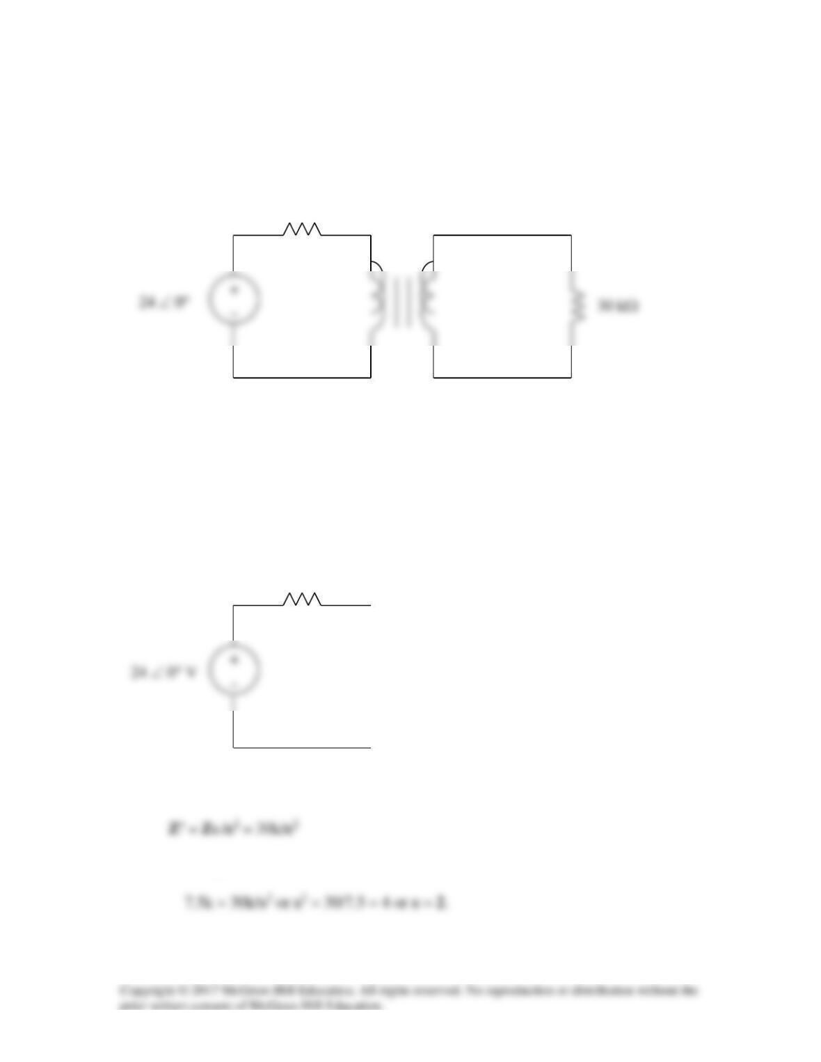
For the circuit in Fig. 13.128, find the turn ratio so that the maximum power is delivered
to the 30-kΩ resistor.
Figure 13.128
For Prob. 13.64.
Solution
The Thevenin equivalent to the left of the transformer is shown below.
The reflected load impedance is
For maximum power transfer,
7.5 kΩ
7.5 kΩ
•
•
1:n
Solution 13.65
For the circuit in Fig. 13.128, find the turn ratio so that the maximum power is delivered
to the 30-kΩ resistor.
Solution
The Thevenin equivalent to the left of the transformer is shown below.
The reflected load impedance is
For maximum power transfer,
7.5 kΩ
7.5 kΩ
•
•
1:n
Solution 13.66
Design a problem to help other students to better understand how the ideal
autotransformer works.
Although there are many ways to solve this problem, this is an example based on the
same kind of problem asked in the third edition.
Problem
Solution
v1 = 420 V (1)

Solution 13.67
An autotransformer with a 40% tap is supplied by an 880-V, 60-Hz source and is used for
step-down operation. A 5-kVA load operating at unity power factor is connected to the
secondary terminals. Find: (a) the secondary voltage, (b) the secondary current, (c) the
primary current.
Solution
1
NN
V
21
1==→=
+
Solution 13.68
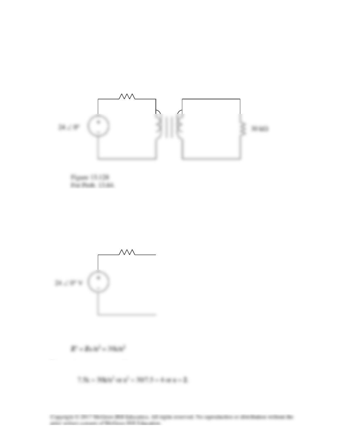
In the ideal autotransformer of Fig. 13.130, calculate I1, I2, and Io. Find the average
power delivered to the load.
Figure 13.130
For Prob. 13.68.
Solution
This is a step-up transformer.
I1
At the autotransformer terminals,
+
I2
120∠45° V

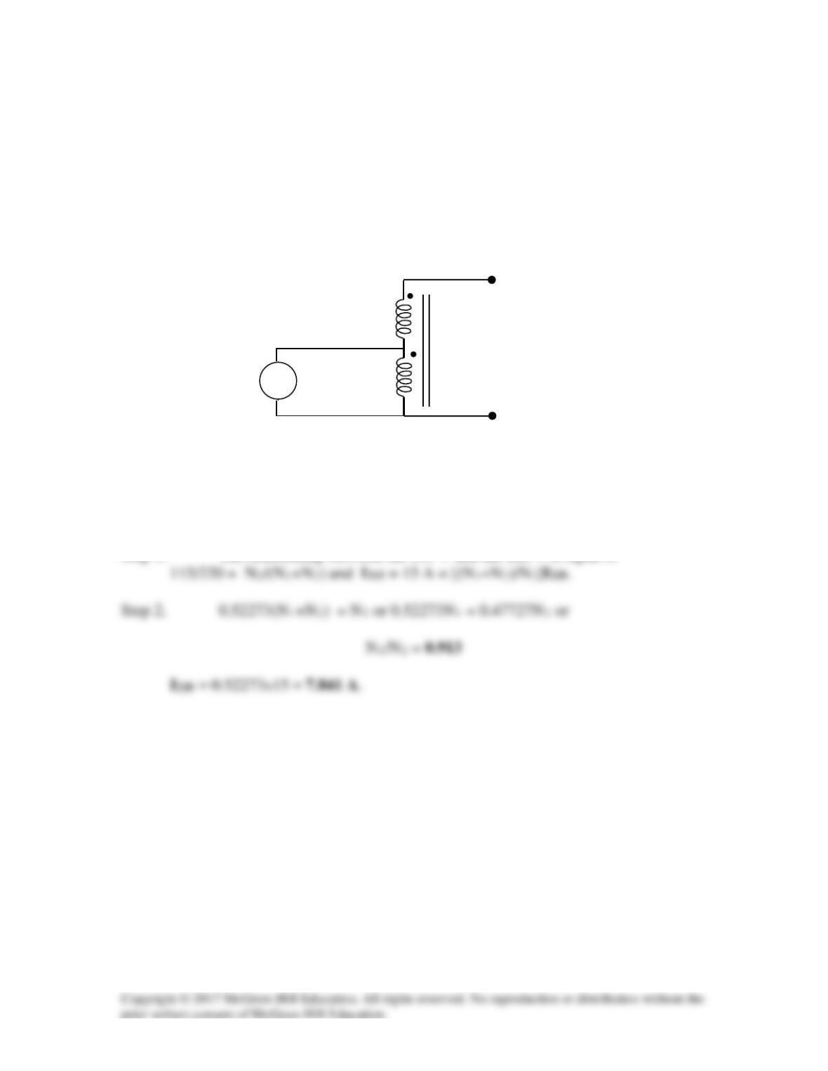
Solution 13.69
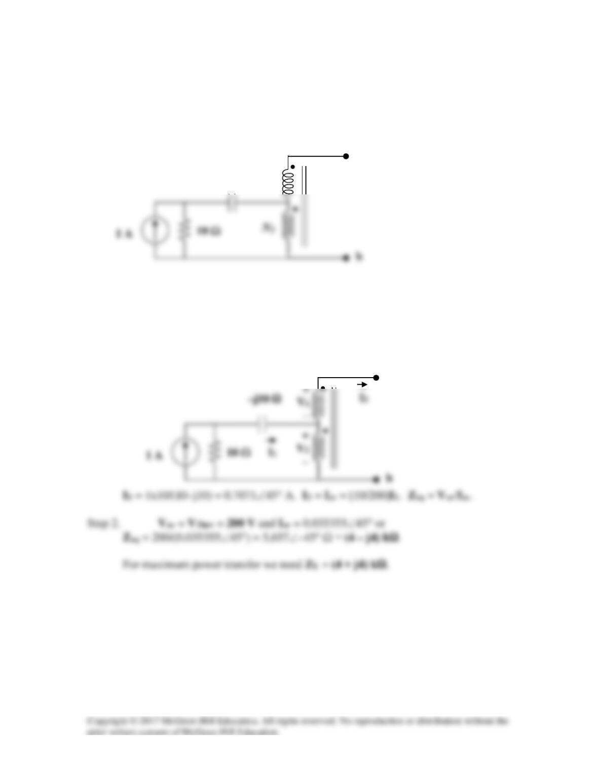
In the circuit of Fig. 13.131, N1 = 190 turns and N2 = 10 turns, determine the Thevenin
equivalent circuit looking into terminals a and b. What would be the value of ZL that
would absorb maximum power from the circuit?
Figure 13.131
For Prob. 13.69.
Solution
Step 1. For the open circuit, I1 = 0 and I2 = 0. Thus, Voc = [(190+10)/10](1×10)
= VThev. For the short circuit current, V1 and V2 are equal to zero.
–j10 Ω
N1
–j10 Ω
a
a
Solution 13.70
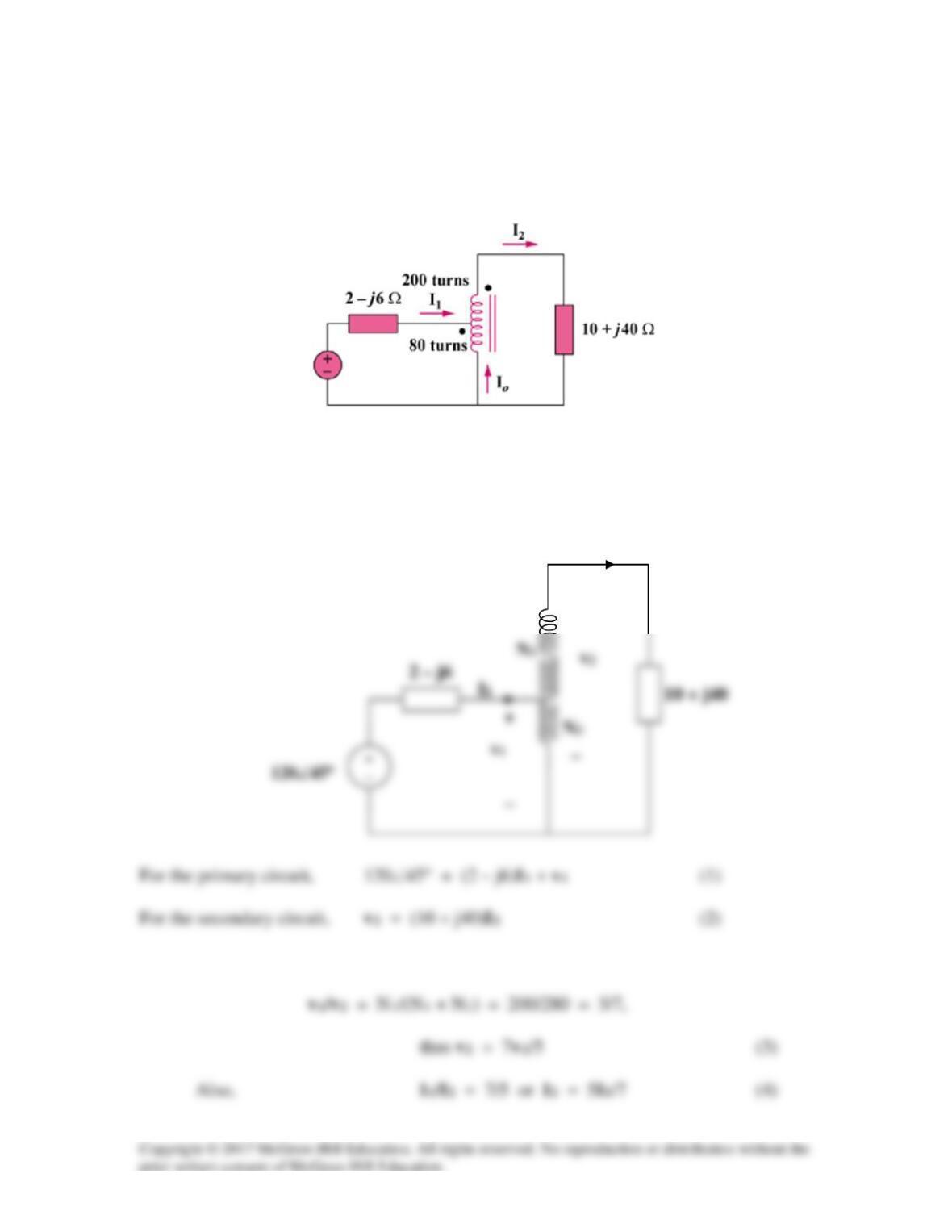
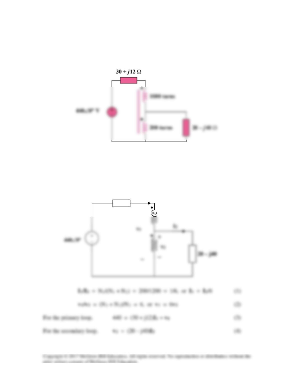
In the ideal transformer circuit shown in Fig. 13.132, determine the average power
delivered to the load.
Figure 13.132
For Prob. 13.70.
Solution
This is a step-down transformer.
30 + j12
+
I1

Substituting (1) and (2) into (3),
and substituting (4) into this yields
Solution 13.71
When individuals travel, their electrical appliances need to have converters to match the
voltages required by their appliances to the local voltage available to power their
appliances. Today these converters use power electronics to convert voltages. In the past
these converters were auto transformers. The auto transformer shown in Fig. 134 is used
to convert 115 volts to 220 volts. What is the value of the turns? If the maximum current
available from the 115 V source is 15 amps, what will be the maximum current available
for the 220 V appliance?
Figure 13.133
For Prob. 13.71.
Solution
Step 1. The relationship between the 115 V and the 220 V is equal to
+
220 V
−
N1
N2
115 V
+
−
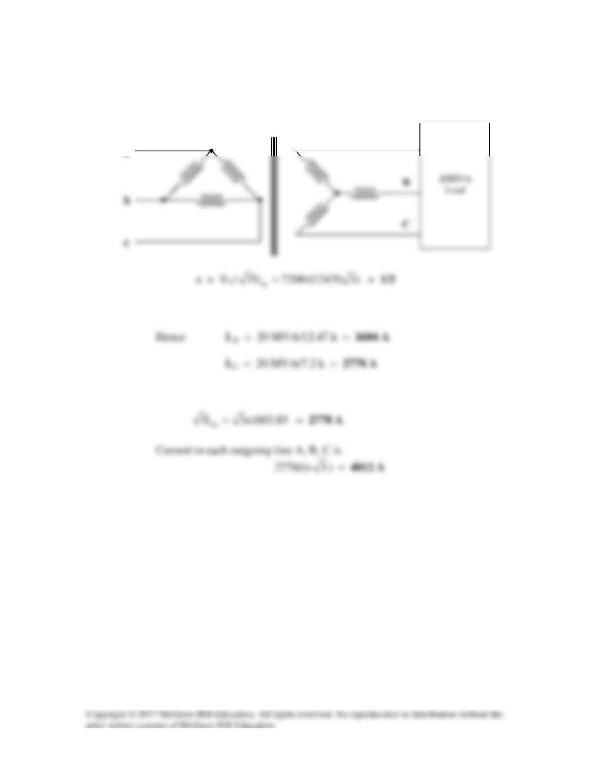
Solution 13.72
(a) Consider just one phase at a time.
c
b
C
(b) The load carried by each transformer is 60/3 = 20 MVA.
(c) The current in incoming line a, b, c is
1:n
a
A

Solution 13.73
(a) This is a three–phase ∆–Y transformer.
(b) VLs = nvLp /3 = 450/(3
3
) = 86.6 V, where n = 1/3
As a Y–Y system, we can use per phase equivalent circuit.
3
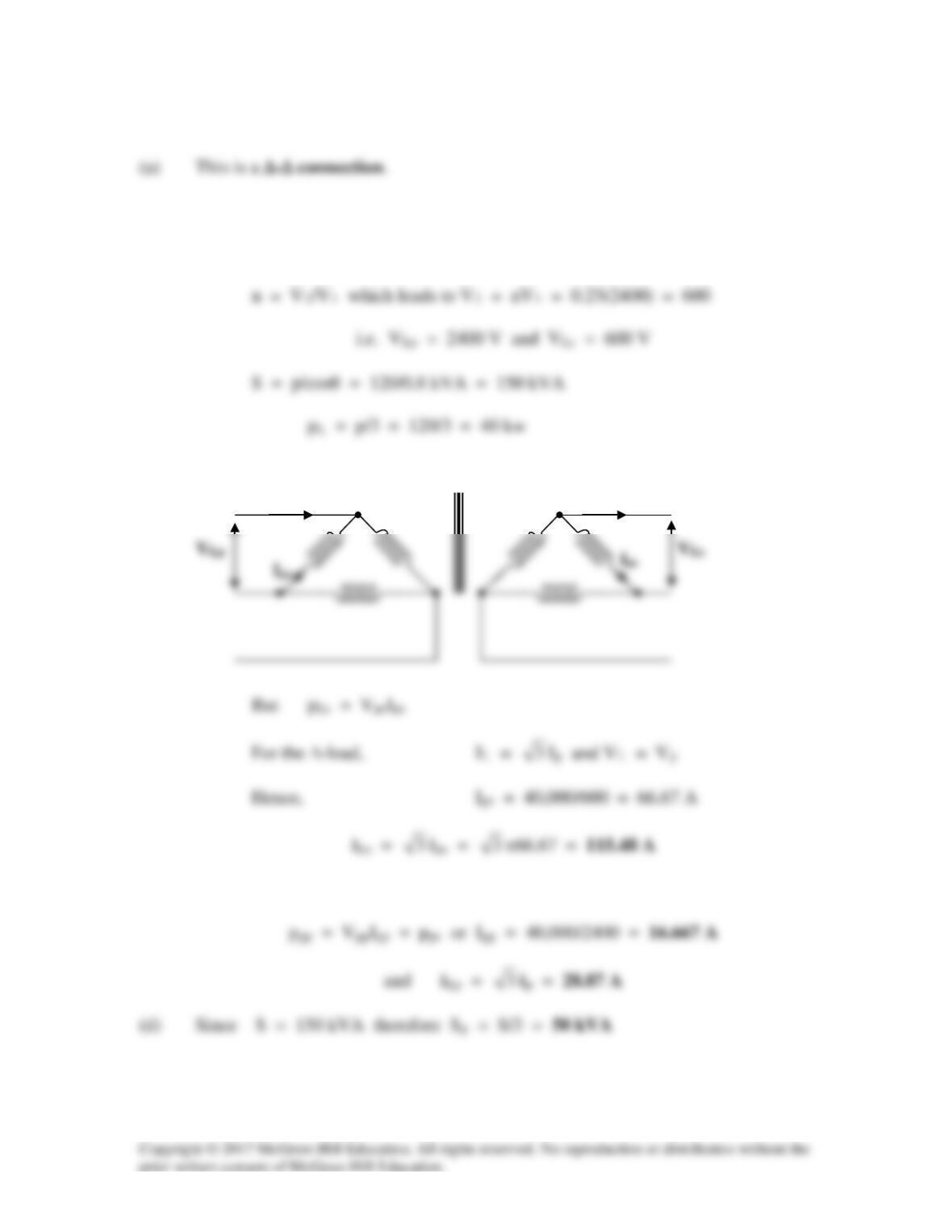
Solution 13.74
(b) The easy way is to consider just one phase.
1:n = 4:1 or n = 1/4
I
I
(c) Similarly, for the primary side
4:1
I
Ls
I
L

Solution 13.75
Solution 13.76
Using Fig. 13.138, design a problem to help other students to better understand a wye-
delta, three-phase transformer and how they work.
Although there are many ways to solve this problem, this is an example based on the
same kind of problem asked in the third edition.
Problem
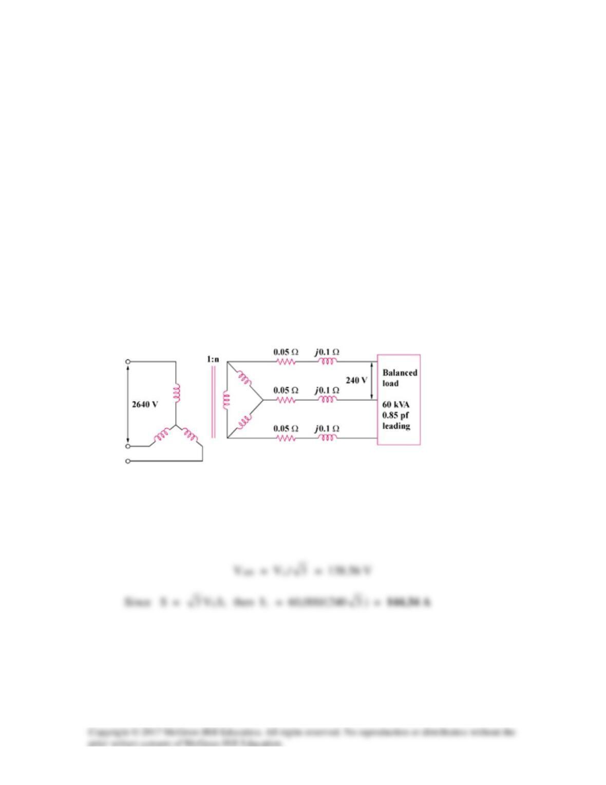
A Y–∆ three–phase transformer is connected to a 60-kVA load with 0.85 power factor
(leading) through a feeder whose impedance is 0.05 + j0.1Ω per phase, as shown in
Fig. 13.137 below. Find the magnitude of:
(a) the line current at the load,
(b) the line voltage at the secondary side of the transformer,
(c) the line current at the primary side of the transformer.
Figure 13.137
Solution
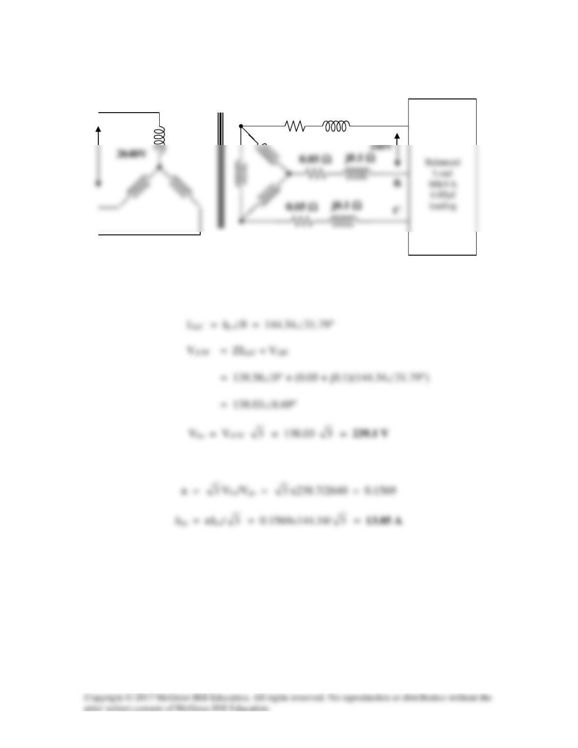
(a) At the load, VL = 240 V = VAB
C
j0.1 Ω
0.05 Ω
j0.1 Ω
0.05 Ω
(b) Let VAN = |VAN|∠0° = 138.56∠0°
cosθ = pf = 0.85 or θ = 31.79°
(c) For Y–∆ connections,
1:n
A
j0.1 Ω
0.05 Ω