Solution 11.54
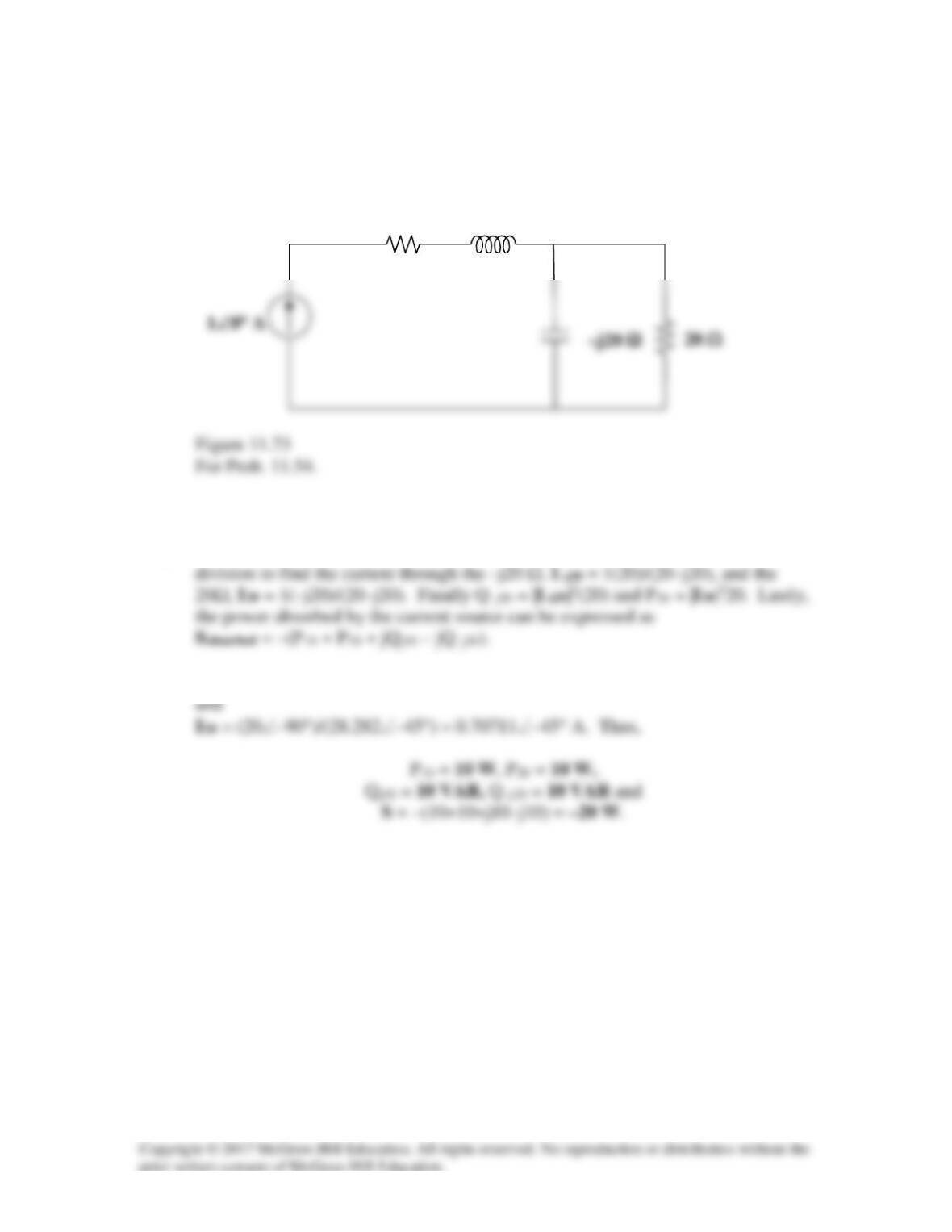
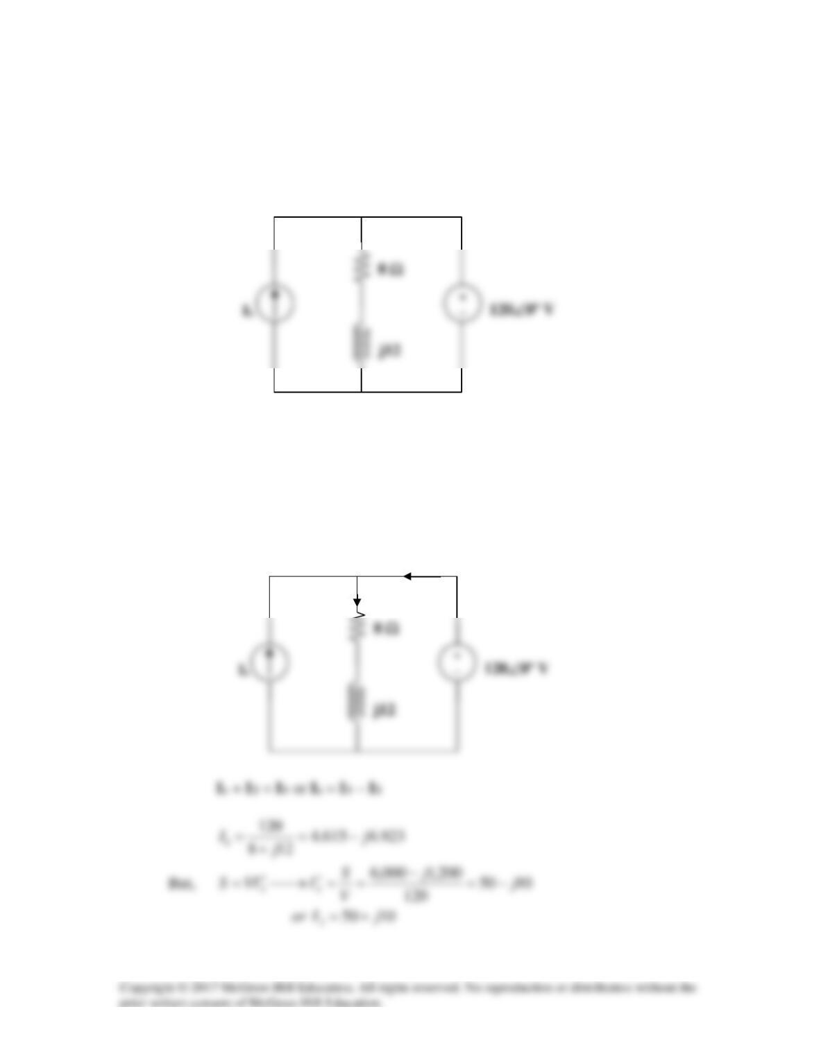
For the network in Fig. 11.73, find the complex power absorbed by each element.
Solution
Step 1. P10 = (1)210, Qj10 = (1)2(10), and we need to determine the current
Step 2. P10 = 10 W, Qj10 = 10 VAR, I–j20 = 20/(28.282∠–45°) = 0.7071∠45° A,
j10 Ω
10 Ω
Solution 11.55
Using Fig. 11.74, design a problem to help other students to better understand the
conservation of AC power.
Although there are many ways to work this problem, this is an example based on the
same kind of problem asked in the third edition.
Problem
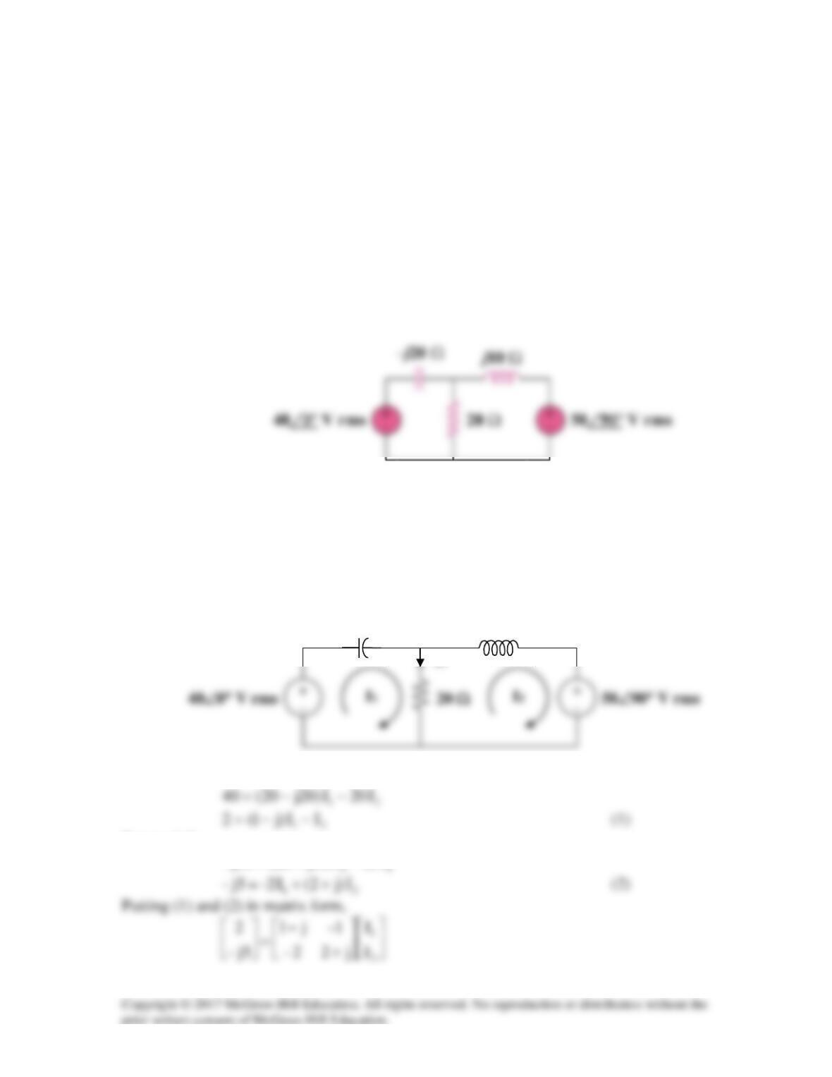
Find the complex power absorbed by each of the five elements in the circuit of Fig.
11.74.
Figure 11.74
Solution
We apply mesh analysis to the following circuit.
For mesh 1,
For mesh 2,
I1
I2
j10 Ω
-j20 Ω
I3
213
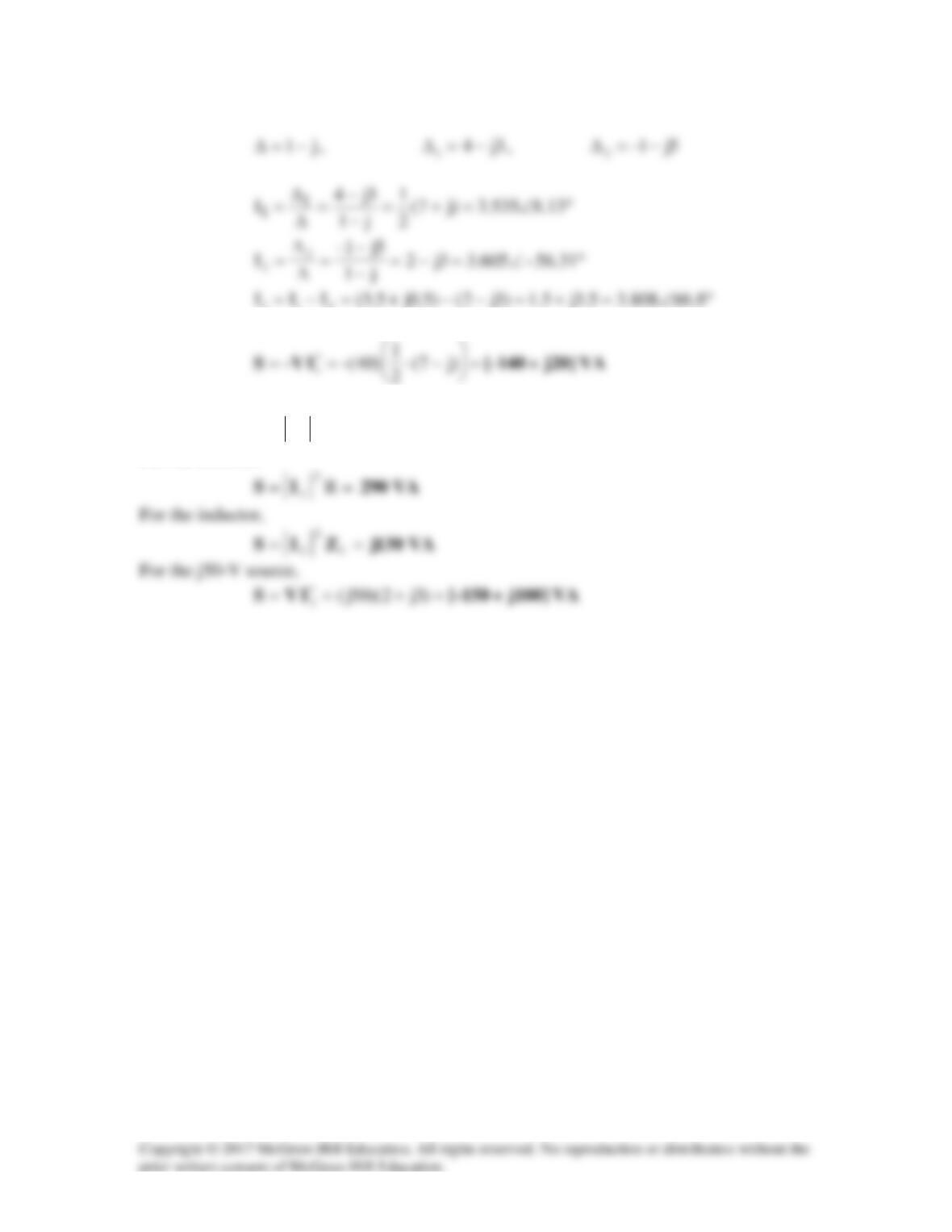
For the 40-V source,
For the capacitor,
== c
2
1ZIS
VA
j250–
For the resistor,
Solution 11.56
8.16.0565.71897365.1
9012
)2–)(6(
6||2– j
j
j−=°−∠=
°−∠
=
=
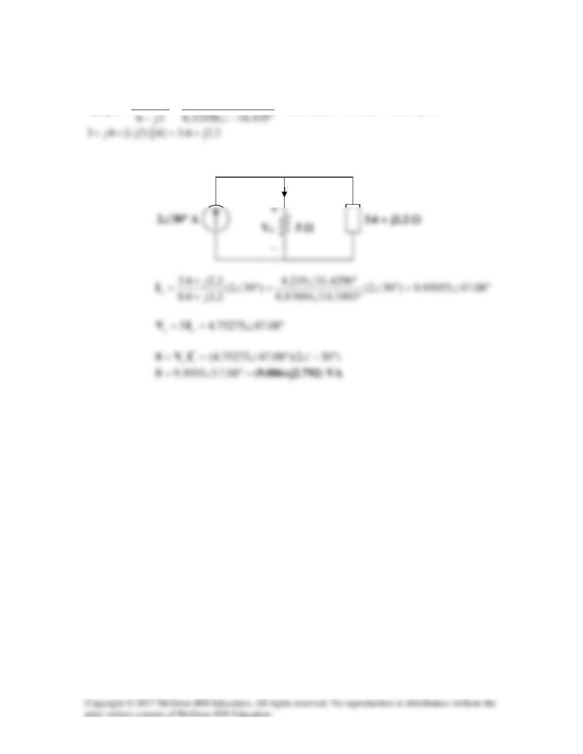
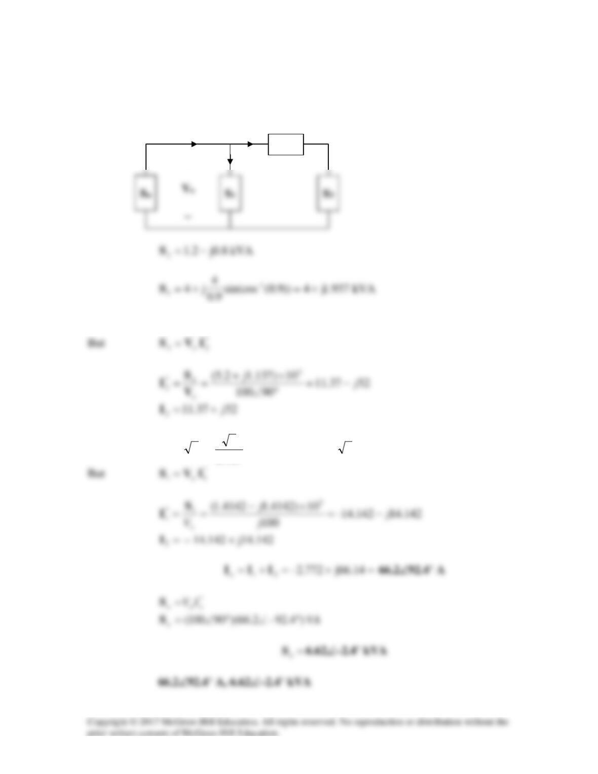
The circuit is reduced to that shown below.
Io
Solution 11.57
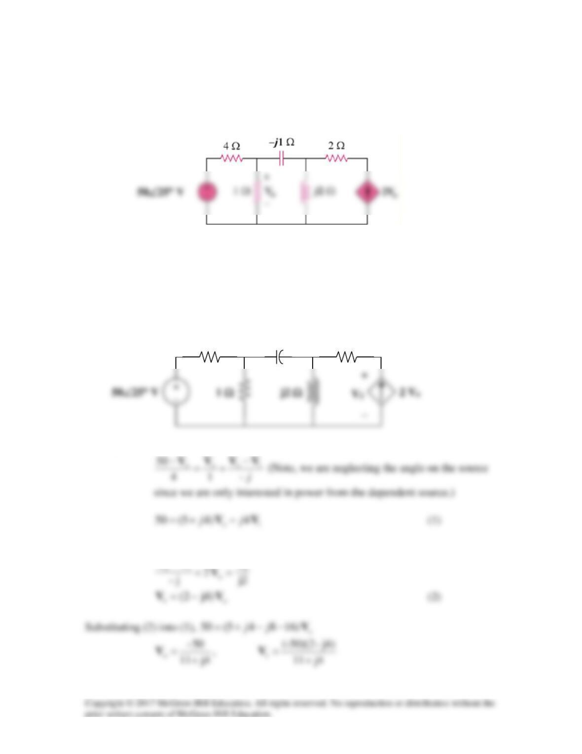
For the circuit in Fig. 11.76, find the average, reactive, and complex power delivered by
the dependent voltage source.
Figure 11.76
For Prob. 11.57.
Solution
Consider the circuit as shown below.
At node o,
At node 1,
V
VV =+
−
2 Ω
–j1 Ω
4 Ω
Vo
V1
The voltage across the dependent source is
o1o12
4)2)(2( VVVVV +=+=
Solution 11.58
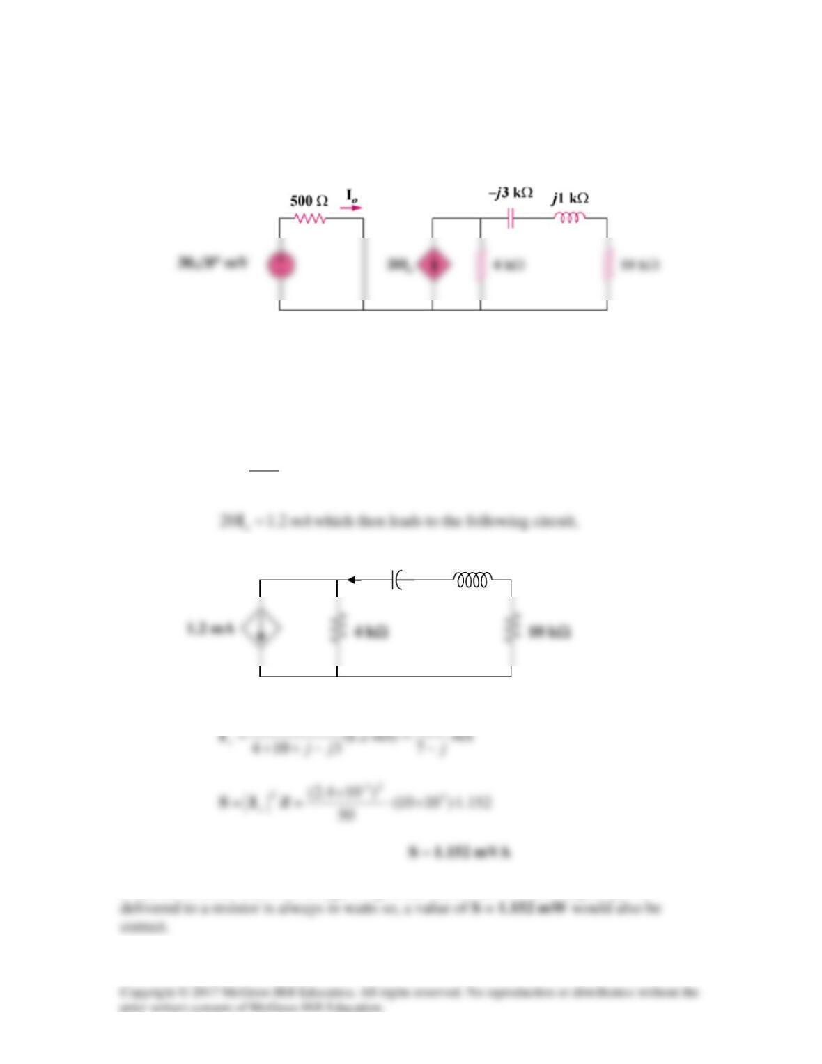
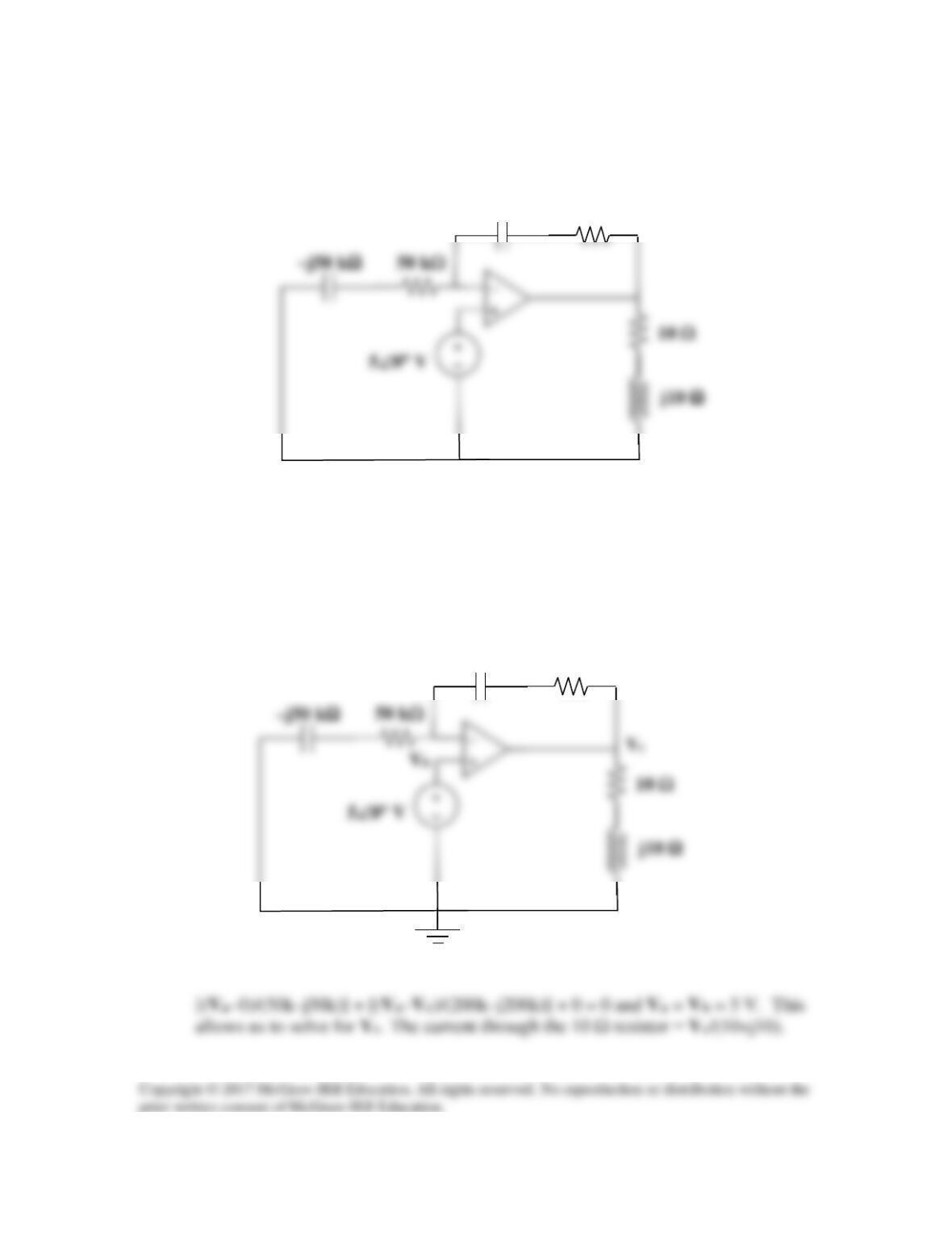
Obtain the complex power delivered to the 10-kΩ resistor in Fig. 11.77 below.
Figure 11.77
For Prob. 11.58.
Solution
From the left portion of the circuit,
A
o
µ
60
500
03.0 ==I
From the right portion of the circuit,
4.2
4
It should be noted that even though we give the answer in VA, the complex power
j1 kΩ
–j3 kΩ
Ix
Solution 11.59
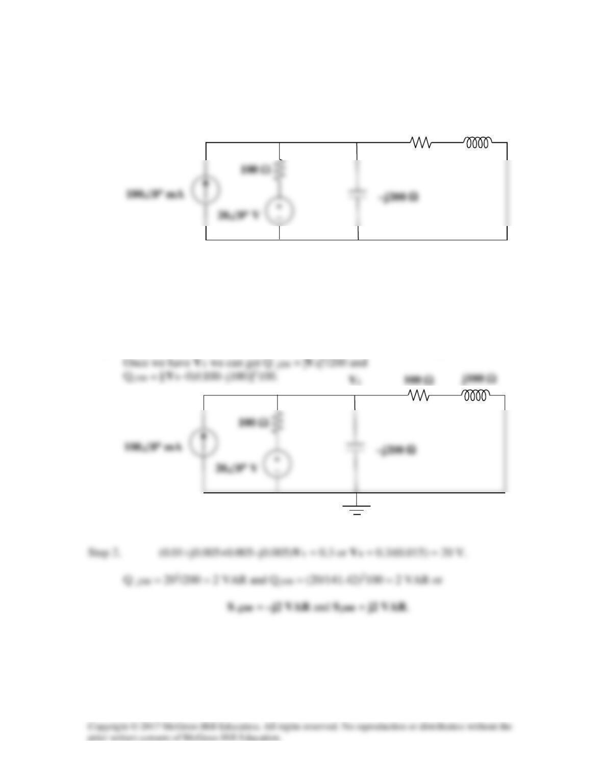
Calculate the reactive power in the inductor and capacitor in the circuit of Fig. 11.78.
Figure 11.78
For Prob. 11.59.
Solution
Step 1. We write a nodal equation and solve for V1 in the following circuit.
–0.1 + [(V1–20)/100] + [(V1–0)/(–j200)] + [(V1–0)/(100+j100)] = 0.
j100 Ω
100 Ω
Solution 11.60
15j20))8.0(sin(cos
20
j20S
1–
1
+=+=
Solution 11.61
Consider the network shown below.
S3
Let
kVA137.1j2.5
324
+=+= SSS
Similarly,
kVA)j1(2))707.0(sin(cos
707.0
2
j2
1–
1
−=−=S
S2
Io
+
I1
I2
Solution 11.62
Consider the circuit below.
25.11j15))8.0(sin(cos
8.0
15
j15 1–
2−=−=S
843.4j10))9.0(sin(cos
9.0
10
j10 1–
1+=+=S
But
*
111 IVS =
0.2 + j0.04 Ω
I
I2
0.3 + j0.15 Ω
−
−
Solution 11.63
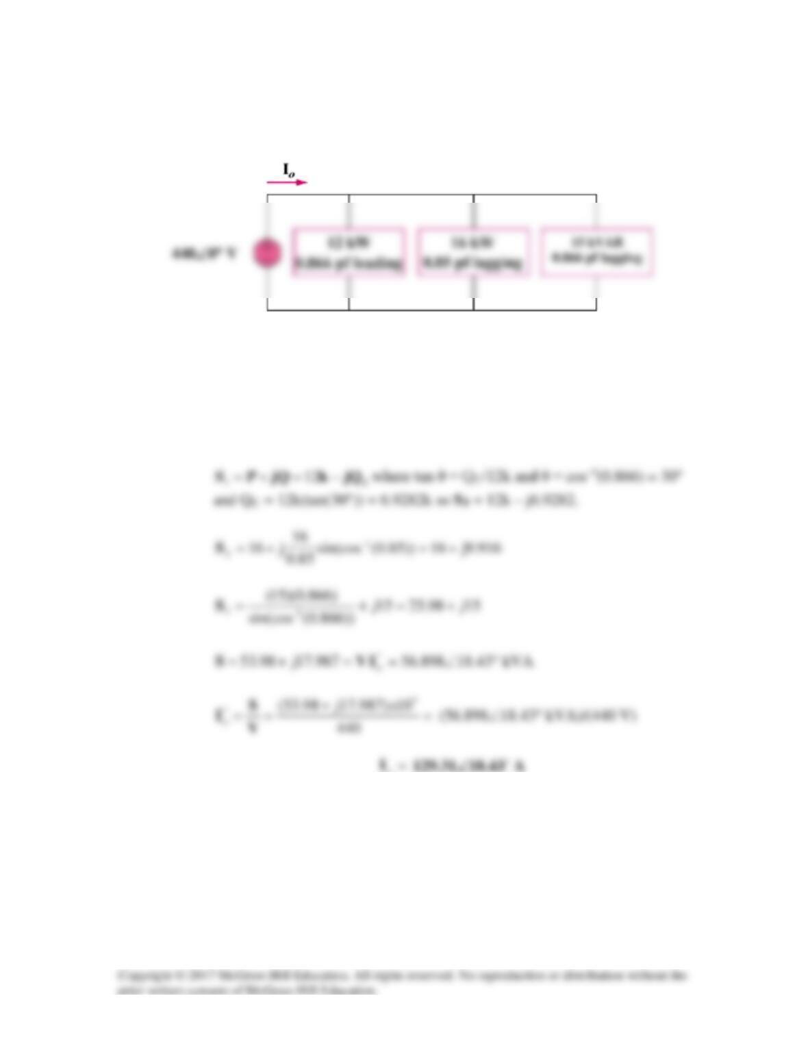
Find Io in the circuit of Fig. 11.82.
Figure 11.82
For Prob. 11.63.
Solution
Let
321
SSSS ++=
.
o
Solution 1l.64
Determine Is in the circuit shown in Fig. 11.83, if the voltage source supplies 6 kW and
1.2 kVAR (leading).
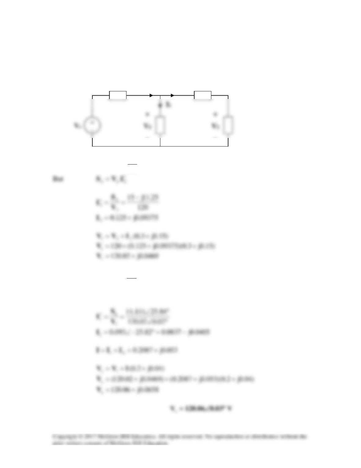
Figure 11.83
For Prob. 11.64.
Solution
I2
I1
Solution 11.65
At the noninverting terminal,
j1
4
j100–100
04
o
oo
+
=→=
−°∠ V
VV
–j200 kΩ
200 kΩ
Va
Solution 11.66
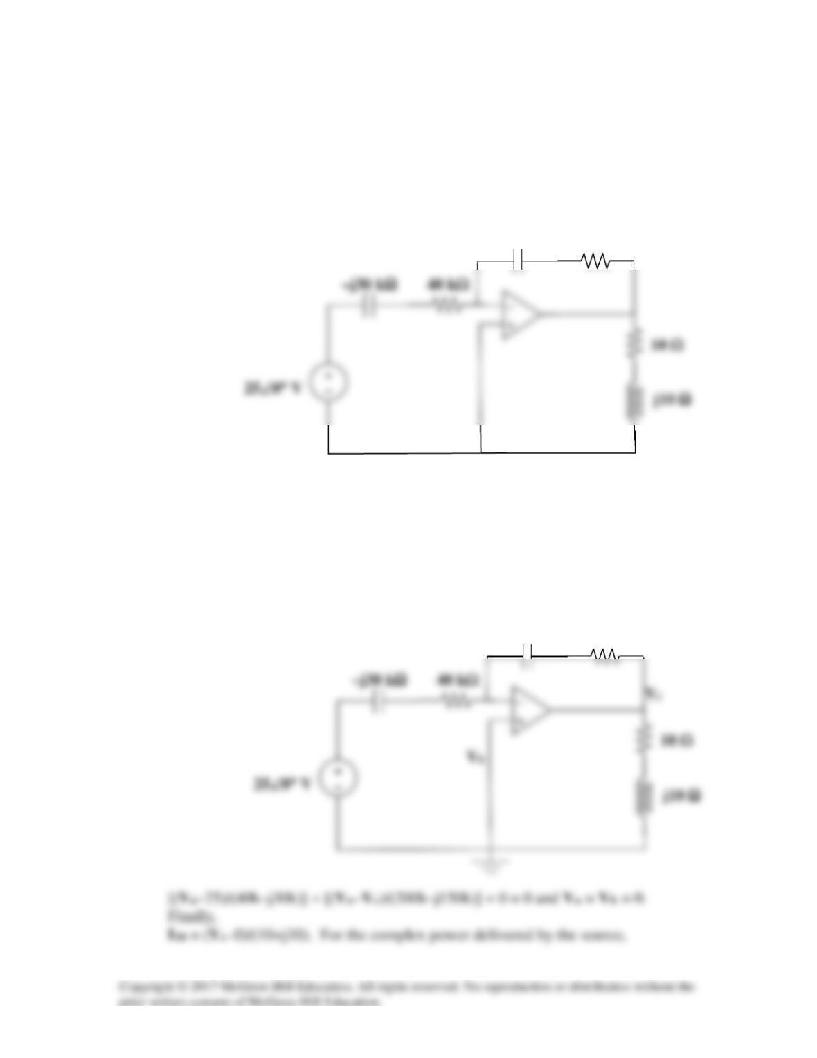
Obtain the average power absorbed by the 10-Ω resistor in the op amp circuit in Fig.
11.85.
10 Ω
–j50 kΩ
Figure 11.85
For Prob. 11.66.
Solution
Step 1. First we identify a reference node and then label the unknown nodes.
Finally we write the node equations and use the constraint equation to solve for
the unknown nodes.
–j200 kΩ
200 kΩ
10 Ω
10 Ω
–j30 kΩ
–j150 kΩ
200 kΩ
Va
Solution 11.67
For the op amp shown in Fig. 11.86, calculate:
(a) the complex power delivered by the voltage source
(b) the average power dissipated by the 10-Ω resistor
–j30 kΩ
Figure 11.86
For Prob. 11.67.
Solution
Step 1. First we establish a reference node and then identify the unknown nodes.
Next we write node equations and apply the constraint equation.
–j150 kΩ
200 kΩ
Is = 25/(40k–j30k) and Sdelivered = 25(Is)*.